TERMOTEK P320-20240 User manual

Version 1.1 P300 WW
Im Rollfeld 6
Phone: +49(0)7221/97 11-0 –Fax: +49(0)7221/97 11-111
76532 Baden-Baden, Germany
E-Mail: info@termotek.de - www.termotek.de
INSTRUCTION BOOK
P320-20240
Keep for later use!

Version 1.1 P300
Im Rollfeld 6
Phone: +49(0)7221/97 11-0 –Fax: +49(0)7221/97 11-111
76532 Baden-Baden, Germany
E-Mail: info@termotek.de - www.termotek.de
2
Termotek AG reserves the right to make technical changes or improvements to this document
without giving prior notice. Furthermore, it is possible that the customer wishes to make
modifications such as colour, side panels, level display, conductivity measurement, voltage,
frequency, which lead to inaccuracies in the displayed photos.
No part of this document may be copied in any way or transmitted without written permission of
Termotek AG.
© Termotek AG, Baden-Baden, 2013
All rights reserved.

Version 1.1 P300
Im Rollfeld 6
Phone: +49(0)7221/97 11-0 –Fax: +49(0)7221/97 11-111
76532 Baden-Baden, Germany
E-Mail: info@termotek.de - www.termotek.de
3
CONTENTS
1. NOTES TO USING THIS MANUAL................................................................................................. 4
2. SUMMARY OF THE WARNING AND PRECAUTIONARY NOTES................................................ 6
3. INTRODUCTION.............................................................................................................................. 7
3.1 PRODUCT DESCRIPTION .........................................................................................................................7
3.2 NOTES TO APPLICATION.........................................................................................................................7
3.2.1 Electrical safety..................................................................................................................8
3.2.2 Operational safety.............................................................................................................. 8
3.2.3 Safety labels....................................................................................................................... 8
4. GETTING STARTED........................................................................................................................ 9
4.1 UNPACKING THE UNIT............................................................................................................................9
4.2 OPERATING THE CHILLER.....................................................................................................................10
4.2.1 Positioning........................................................................................................................ 10
4.2.2 Connecting the water hoses............................................................................................. 10
4.2.3 Setting Up the Electrical Connections..............................................................................11
4.2.4 Getting ready to operate .................................................................................................. 13
4.3 PREPARING THE COOLANT WATER-FEEDBACK CHILLER FOR TRANSPORT TO THE CUSTOMER...............13
4.3.1 Storage............................................................................................................................. 13
4.3.2 Place of Operation ...........................................................................................................14
4.3.3 Transport to the customer................................................................................................14
5. SYSTEM DESCRIPTION............................................................................................................... 15
5.1 SET UP AND FUNCTION.........................................................................................................................15
5.1.1 Refrigerant circuit............................................................................................................. 15
5.1.2 Coolant water circuit......................................................................................................... 16
5.1.3 Industrial water circuit ......................................................................................................17
5.1.4 Electrical circuit................................................................................................................19
6. MAINTENANCE WORK................................................................................................................. 23
6.1 SAFETY NOTES.....................................................................................................................................23
6.2 REPLACING THE WATER FILTER............................................................................................................23
6.3 REFILLING WATER................................................................................................................................25
6.4 REPLACING THE WATER.......................................................................................................................26
6.5 REFRIGERANT CIRCUIT ........................................................................................................................27
7. INSTRUCTIONS FOR REPAIR. .................................................................................................... 28
7.1 SAFETY NOTES.....................................................................................................................................28
7.2 REPAIRS TO THE ELECTRICAL CIRCUIT .................................................................................................29
7.2.1 Replacing the fuses.......................................................................................................... 29
8. OTHER........................................................................................................................................... 30
8.1 SERIAL NUMBER ..................................................................................................................................30
8.2 WASTE DISPOSAL INSTRUCTION...........................................................................................................30
8.3 NOT SATISFIED?...................................................................................................................................31

Version 1.1 P300
Im Rollfeld 6
Phone: +49(0)7221/97 11-0 –Fax: +49(0)7221/97 11-111
76532 Baden-Baden, Germany
E-Mail: info@termotek.de - www.termotek.de
4
1.Notes to using this manual
This manual has been designed to support the user with the transport, installation,
commissioning, operation, inspection, servicing and repair of the unit.
The user should read the manual before beginning to install the unit. Termotek AG takes no
responsibility for damage caused through incorrect installation, commissioning, repair or
operation of this unit.
This chiller complies with the current European standards. Changes made to the construction or
deviations from the intended application by the customer can void this compliance.
Version 1.1 P300
Im Rollfeld 6
Phone: +49(0)7221/97 11-0 –Fax: +49(0)7221/97 11-111
76532 Baden-Baden, Germany
E-Mail: info@termotek.de - www.termotek.de
5
The notational convention to this user manual
The following notation and symbols apply throughout the whole document.
CAUTION.DANGER!
CAUTION.CORROSIVE MATERIAL
CAUTION.HOT OR COLD SURFACES
CAUTION.ELECTRICAL VOLTAGE
CAUTION.NOXIOUS MATERIAL
RE-MOVE PLUG BEFORE OPENING
USEFUL INFORMATION

Version 1.1 P300
Im Rollfeld 6
Phone: +49(0)7221/97 11-0 –Fax: +49(0)7221/97 11-111
76532 Baden-Baden, Germany
E-Mail: info@termotek.de - www.termotek.de
6
2. Summary of the warning and precautionary notes
Service and repair work should only be carried out by appropriately qualified personnel.
Undertake no work on the refrigerant circuit as there is a danger that poisonous and
corrosive gas (R134a) may leak out. Any work carried out on the refrigerant circuit must be
carried out by refrigeration experts. (Refrigerant R134a).
When working on the chiller, ensure that the unit is disconnected from the power supply.
Switch the power supply off. Ensure that unauthorised reconnection of the power supply is
not possible.
Do not disable any security measures.
The electrical connection is designed according to the VDE and the EN- and IEC-
Standards. Ensure that the live and neutral wires are correctly connected. Furthermore,
ensure that the unit is correctly earthed.
Do not operate the unit without water to avoid damaging internal components e.g. pump.
Use only filtered (less than 50 µm) industrial water in accordance to the specification
chapter 5.1.3.
Do not operate the chiller unit without a water filter.
Refill the unit only with the permitted filtered (< 25 µm)coolant water.
Do not use or maintain the chiller outdoors. These units were not designed to withstand
outdoor weather conditions.
Ensure that sufficient air circulation is maintained to guarantee the required heat transfer.
Do not alter the controller setting. An altered setting can render the unit non-functional.
Note the water flow direction when connecting the water hoses.
Before transporting the unit, it must be thoroughly drained. Otherwise it is possible that the
unit be damaged by residual water freezing inside the unit.
Version 1.1 P300
Im Rollfeld 6
Phone: +49(0)7221/97 11-0 –Fax: +49(0)7221/97 11-111
76532 Baden-Baden, Germany
E-Mail: info@termotek.de - www.termotek.de
7
3.Introduction
3.1 Product description
The chiller unit was constructed and developed to maintain the temperature of a user medium
(de-ionised water) between two predefined limits with the help of a cooling process. It has been
designed to operate under continual operation for the purpose of cooling systems such as for
laser equipment. The noise emission is lower than 70dB, in an integrated system.
The chiller operates within is a closed circuit system and is fitted inside a robust and compact
steel enclosure.
Advantages of the chiller unit:
compact enclosure
low service
simple operation and handling
intended for use at ambient temperatures of +15°C to +40°C
reliable, quiet operation
high temperature stability of the coolant water
3.2 Notes to application
The chiller unit is intended, exclusively, to cool filtered (< 25 µm) water in compliance with all the
corresponding installation and safety regulations.
Termotek AG takes no responsibility for damage caused through improper use or improper
operation of the unit.

Version 1.1 P300
Im Rollfeld 6
Phone: +49(0)7221/97 11-0 –Fax: +49(0)7221/97 11-111
76532 Baden-Baden, Germany
E-Mail: info@termotek.de - www.termotek.de
8
3.2.1 Electrical safety
The chiller unit has been built according to the generally recognised technical regulations.
Caution, danger of electrical shock!
Ensure that the unit is disconnected from the power supply before carrying out any assembly
work. All work undertaken on the chiller unit, particularly on electrical equipment, is only to be
carried out by suitably trained personnel.
3.2.2 Operational safety
The chiller unit is a compressor chiller design with a closed cooling circuit.
Attention!
Do not operate the chiller without coolant water. Check the coolant water level at regular
intervals. The chiller is quoted as secondary component of the complete system (Slave). At
error messages of the chiller (low/high temp.), it must be rapidly switched off. If you don’t follow
these instructions, consequential damage to the complete system can’t be ruled out. For these
damages TERMOTEK excludes liability.
3.2.3 Safety labels
Information!
Damaged or unreadable safety labels must be replaced immediately. When reordering please
give the article number.
Version 1.1 P300
Im Rollfeld 6
Phone: +49(0)7221/97 11-0 –Fax: +49(0)7221/97 11-111
76532 Baden-Baden, Germany
E-Mail: info@termotek.de - www.termotek.de
9
4.Getting started
4.1 Unpacking the unit
The chiller contains many electrical and mechanical components. In order to protect the
individual components during transport, a special packaging material has been used. This
material absorbs most of the shock and vibration likely to occur.
The internal packaging material consists of PE - foamed material. The external packing material
used is cardboard. This protects the unit from dust and other pollution.
When unpacking the unit proceed as follows:
1. Check the packaging for signs of damage.
2. Open the packaging and remove the packing foam
3. Take the chiller out.
4. Check the chiller for signs of transport damage.
Information!
Should the chiller have been damaged during transport, inform both the haulage firm and the
supplier in writing without delay. Retain the packaging material and note the external and
internal damage. Take one or more photos.
5. Place the chiller at the planned operating location.
6. Protect the chiller from dirt and dampness prior to installation.
7. Dispose of the packaging material.
Information!
Please ensure that the surrounding cardboard, the transport pallet and the packing foam are
disposed of separately for recycling purposes.
Version 1.1 P300
Im Rollfeld 6
Phone: +49(0)7221/97 11-0 –Fax: +49(0)7221/97 11-111
76532 Baden-Baden, Germany
E-Mail: info@termotek.de - www.termotek.de
10
4.2 Operating the chiller
4.2.1 Positioning
The chiller unit is designed as a 19” euro rack slide-in unit. The chiller must be installed
horizontally. Fasten the chiller with the front panel. Ensure that the chiller lies with the botton
plate on the side rails from the rack.
Ensure that the air flow through the side panels is not restricted. Avoid short circuiting the air
inlet and outlet.
Do not use or maintain the chiller outdoors. These units were not designed to withstand outdoor
weather conditions.
4.2.2 Connecting the water hoses
Before the chiller can be operated together with the user equipment, the water hoses must be
connected correctly. Ensure that the hoses to be used are designed to operate at the maximum
pressure required by the unit. The water connections are located on the rear panel of the chiller.
Connect the water supply to the chiller. Please ensure that the connection points are not under
any strain. If necessary, take steps to ensure that no strain on the connections can occur during
operation of the chiller.
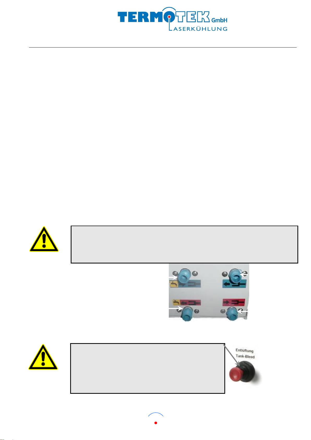
Attention!
Note the direction of flow when connecting the hoses:
Blue label = cold water
Red label = heated water
Industrial water supply inlet (BLUE)
Industrial water supply outlet (RED)
Water outlet (to
user) BLUE
Water inlet (from
user) RED
On the first start you must fill up the pump. Open the bleeding
cap on the front panel of the chiller and the filler. Fill the water in
the chiller via the filler neck on the front panel up to the maximum
water level. Close the bleeding cap.

Version 1.1 P300
Im Rollfeld 6
Phone: +49(0)7221/97 11-0 –Fax: +49(0)7221/97 11-111
76532 Baden-Baden, Germany
E-Mail: info@termotek.de - www.termotek.de
11
4.2.3 Setting Up the Electrical Connections
Connecting the Power Supply
A cable has been fitted on to the rear panel for the purpose of connecting the electrical power
supply. Connect the chiller power supply using an external separator with sufficient contact
separation and ensure that it is located near the chiller unit and is clearly labelled as belonging
to the unit. Use a 16A. fuse in the power phase. When using an automatic cut out fuse
(Charakteristic C) it is possible to use this as the power supply separator as long as this fulfills
the requirements. The fuses must be designed for inductive loads!
power supply
230 V AC, 50/60 Hz
Signal connector (9pin SUB D, M)
Signal interface RS232 (9pin SUBD, FM)
Version 1.1 P300
Im Rollfeld 6
Phone: +49(0)7221/97 11-0 –Fax: +49(0)7221/97 11-111
76532 Baden-Baden, Germany
E-Mail: info@termotek.de - www.termotek.de
12
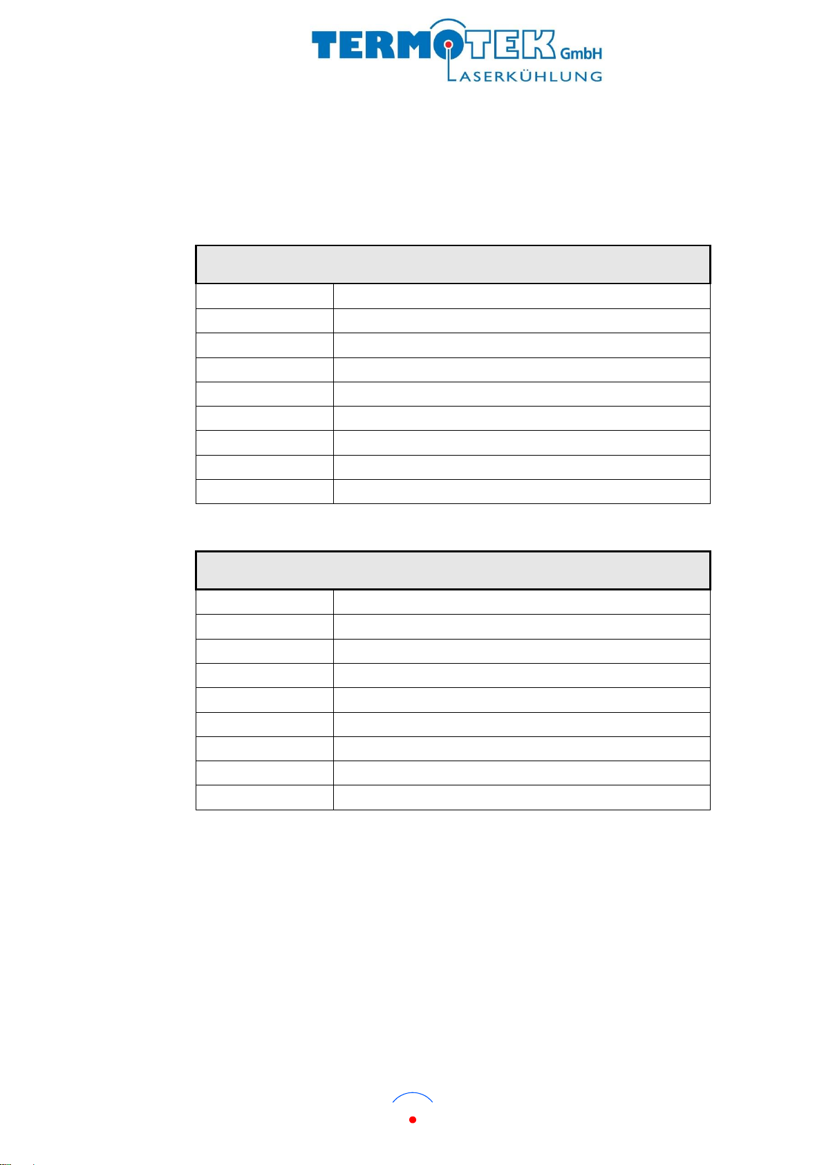
Connections for the data transfer
The 9 pin Sub-D connectors for data transfer and interface are located on the rear panel of the
chiller unit. Open circuit in error case. Maximum load of contacts 150mA/24V.
Signal connector
Pin Connections
Signal Outputs
Pin 1
High pressure
Pin 2
High/low temperature
Pin 3
Flow monitor
Pin 4
Collective fault contact
Pin 5
Alarm water level
Pin 6
Alarm conductivity
Pin 7
Common
Pin 8
GND for remote start from customer
Pin 9
+24 V DC remote start from customer
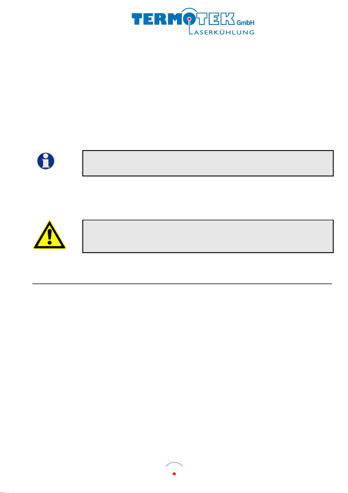
Signal interface RS 232
Pin Connections
Signal Outputs
Pin 1
NC
Pin 2
TxD
Pin 3
RxD
Pin 4
NC
Pin 5
GND
Pin 6
NC
Pin 7
NC
Pin 8
NC
Pin 9
NC
Version 1.1 P300
Im Rollfeld 6
Phone: +49(0)7221/97 11-0 –Fax: +49(0)7221/97 11-111
76532 Baden-Baden, Germany
E-Mail: info@termotek.de - www.termotek.de
13
4.2.4 Getting ready to operate
1. After connecting the power supply, “water level alarm” appears in the chiller controller display
and the red LED lights.
2. Fill the chiller with water using the filler pipe located on the front panel of the chiller until the error
message “water level warning” appears (chap 4.2.2 and 6.3).
3. Continue filling the chiller until no more water level error message appears. Confirm the
message with the quit –key (). The red LED switches off.
4. If the maximum water level is reached, you can switch on the chiller by pressing the UP-button.
If the chiller has the option remote start, it is has to be switched on via remote start.
5. Sometimes the hose system of the laser must be filled. Therefor activate the filling mode in the
2nd programming level and fill the hose system via the filler pipe of the chiller (Chap 5.1.4). The
filling mode disables the water level control and activates the pump for a short period to fill the
hose system in one process.
Fill water in any event if you use the filling mode. Otherwise there is danger of dry
running and damaging of the pump and is danger of damaging the chiller and laser!
4.3 Preparing the coolant water-feedback chiller for transport to
the customer
Since the chiller comprises of a large number of sensitive, electronic and mechanical
components, keep to the following requirements and instructions before storing, installing or
transporting the unit. The chiller weight is ca. 70 kg.
4.3.1 Storage
Should the expected storage time of the chiller exceed four weeks then the coolant water should
be completely drained out of the unit (see chapter 6.4). The chiller must be stored in a horizontal
position. Ensure that the unit is protected from pollution and dampness.
The following ambient conditions are necessary during storage:
Temperature: +5°C to +65°C
Relative humidity: 10 –75%, no condensation
Version 1.1 P300
Im Rollfeld 6
Phone: +49(0)7221/97 11-0 –Fax: +49(0)7221/97 11-111
76532 Baden-Baden, Germany
E-Mail: info@termotek.de - www.termotek.de
14
4.3.2 Place of Operation
Do not install the chiller in an environment where other equipment is likely to cause a high
ambient temperature. The chiller operates efficiently foe ambient temperatures of up to 40°C. An
over-pressure switch protects the refrigerant circuit from pressure increases.
The chiller unit must be installed such that sufficient air circulation can be maintained. Ensure
that the air inlet and outlets of the rack enclosure system are completely unrestricted during
operation at a later date. A restriction of the air flow will have an adverse effect on the cooling
capacity of the unit.
To reduce the vibration the parts from the chiller are mounted on vibration dampers. If the
vibration for the complete unit is too high, mount the whole chiller with the botton plate on
vibration dampers.
4.3.3 Transport to the customer
The chiller should be transported as carefully as possible, with a minimum of shock and
vibration. Please take note of the following precautions:
The chiller must be completely drained before being transported.
The chiller must be kept upright during transport and may not be thrown.
Use only suitable packing materials - which absorb shock and vibration –in order to ensure
that sensitive components inside the chiller are not damaged during transport. Ensure that
the unit is protected from dust and other pollution. Also ensure that the chiller is packed to
prevent damage from shock or being dropped.
Should the chiller be despatched individually, then use the original packing materials.
Ship the chiller only fixed on a pallet.
Before transportation, the packed unit should also be labelled: “protect against moisture“,
“Transport and store this way up“, “Fragile“.
Attention frost damage!
Before transportation, the unit should be completely drained otherwise there is a danger of
residual coolant water freezing and causing damage inside the chiller.

Version 1.1 P300
Im Rollfeld 6
Phone: +49(0)7221/97 11-0 –Fax: +49(0)7221/97 11-111
76532 Baden-Baden, Germany
E-Mail: info@termotek.de - www.termotek.de
15
5.System description
5.1 Set up and function
The chiller is a compressor chiller with a closed coolant circuit. The chiller is a closed unit and
has the following circuits:
Refrigerant circuit
Coolant water circuit
Industrial water circuit
Electrical circuit
5.1.1 Refrigerant circuit
The refrigerant circuit is a closed system, inside which the refrigerant medium circulates.
Within the refrigerant circuit, the compressor sucks gaseous refrigerant medium R 134a out of
the evaporator and compresses it. The heat generated by the compressed refrigerant is
transferred to the industrial water. During this compressing process the refrigerant changes from
gas to fluid.
The refrigerant fluid then passes through the dryer, which removes any residual moisture, and is
finally injected into the tank (heat exchanger) via an expansion valve (nozzle). The refrigerant
evaporates at the reduced pressure, and takes the energy required for this process from the
coolant water circuit. This results in the coolant water being cooled.
Version 1.1 P300
Im Rollfeld 6
Phone: +49(0)7221/97 11-0 –Fax: +49(0)7221/97 11-111
76532 Baden-Baden, Germany
E-Mail: info@termotek.de - www.termotek.de
16
5.1.2 Coolant water circuit
The warm water flows into the chiller via the water inlet hose. A flow monitor, located directly
after the water inlet point, monitors the flow in the water circuit. The water flows through the heat
exchanger into the tank. The heat is transferred in the heat exchanger.from the refrigerant to the
coolant water. The cooled water is then pumped out of the tank into the pump.
The coolant water flows from the pump to the filter. The filter removes minute dirt particles out of
the water. After passing through the filter, the coolant water flows out of the chiller via the chiller
outlet hose.
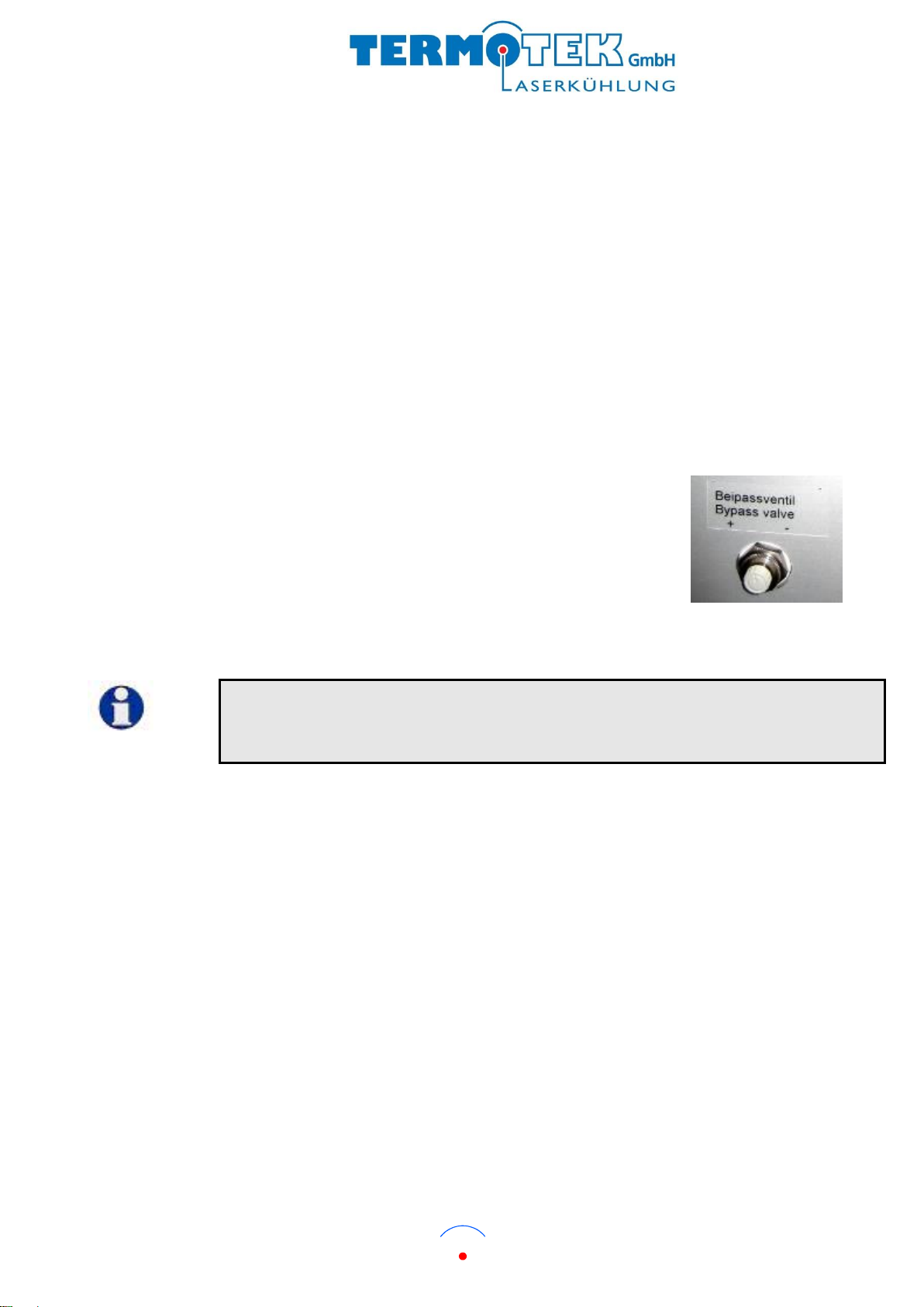
Bypass on front panel
A bypass valve is mounted. You can adjust the flow to the
heat source +/- 30 % there. The chiller has to work while
adjusting! To adjust proceed as follows:
Adjust the required flow. Therefore adjust the valve and
check the flow on the display.
Information!
The filter should be changed at regular intervals. More detailed information can be found in the
chapters for Service work and Replacing the filter.

Version 1.1 P300
Im Rollfeld 6
Phone: +49(0)7221/97 11-0 –Fax: +49(0)7221/97 11-111
76532 Baden-Baden, Germany
E-Mail: info@termotek.de - www.termotek.de
17
5.1.3 Industrial water circuit
The industrial water supply flows in the chiller then it flows through a filter. The industrial water
cools, via the heat exchanger, the refrigerant to the required temperature.
After passing through the heat exchanger, the warmed supply water flows back out of the chiller.
Specification for industrial water
To minimize chiller troubles you should maintain the following values for water contents and their
parameters.
Contamination
Please regard to maintain the DIN regulations for drinking- and heating water, Vd-TÜV
(Technical Inspections Authority) guidelines and the AGFW regulations for water contents.
(See chart 1)
Chart 1:
Water content + parameter
unity
Value
PH Value
°dH
7-9
Total hardness of water
mg/l
6-15
Filtered substances
mg/l
< 30
Chlorides (up to water temperature of 50°C)
mg/l
< 200
Free chlorine
mg/l
< 0,5
Sulfate
mg/l
< 100
Sulfide
mg/l
< 1
Conductivity
µS/cm
10-500
Hydrosulfide
mg/l
< 0,05
Ammoniac
mg/l
< 2
Hydrogencarbonate
mg/l
< 300
Hydrogencarbonate / Sulfide
mg/l
< 1
Nitrate
mg/l
< 100
Nitrite
mg/l
< 0,1
Dissolved ferric
mg/l
< 0,2
Manganese
mg/l
< 0,1
Free aggressive carbonic acid
mg/l
< 20

Version 1.1 P300
Im Rollfeld 6
Phone: +49(0)7221/97 11-0 –Fax: +49(0)7221/97 11-111
76532 Baden-Baden, Germany
E-Mail: info@termotek.de - www.termotek.de
18
Cleaning
Should you expect a coating to be generated due to the water quality ( such as a high
water hardness or pollution), clean the chiller (heat exchanger) regularly.
It is possible to clean the heat exchanger by rinsing it against the flow direction.
The tolerable chloride concentration changes depending on the water temperature (see chart 2).
Chart 2:
Version 1.1 P300
Im Rollfeld 6
Phone: +49(0)7221/97 11-0 –Fax: +49(0)7221/97 11-111
76532 Baden-Baden, Germany
E-Mail: info@termotek.de - www.termotek.de
19
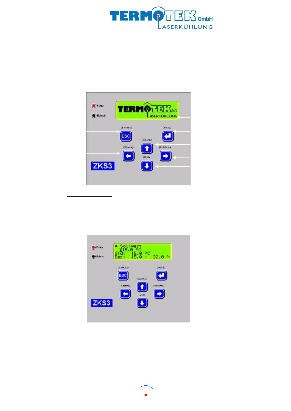
5.1.4 Electrical circuit
The operational mode is indicated by lighting of the green LED. If a fault occurs, the red LED will
light. It depends to the fault and the adjusted parameters whether the chiller discontinues
operating. In this case, the green LED goes out. The beeper can be disabled by pressing the
mute-button. The error messages are self-explanatory.
error LED
operational mode LED
ESCAPE/set value
LEFT/mute
display
ENTER/menu
UP/on/off
RIGHT/roll/info
DOWN/quit
Adjusting set value
By pressing the escape-button, you can reach the set value display (1st programming level). By
pressing the UP- and DOWN-button you can adjust the value of the digit, with the RIGHT- and
LEFT-button you can choose the digit. The set value is affirmed by pressing the ENTER-button,
you can cancel the input by pressing the ESCAPE-button.

Version 1.1 P300
Im Rollfeld 6
Phone: +49(0)7221/97 11-0 –Fax: +49(0)7221/97 11-111
76532 Baden-Baden, Germany
E-Mail: info@termotek.de - www.termotek.de
20
Adjusting parameters
By pressing the ENTER-button, you can reach the 2nd programming level. Therefor, please enter
your user-password (0020). By pressing the UP- and DOWN-button you can adjust the value of
the digit, with the RIGHT- and LEFT-button you can choose the digit. The set value is affirmed by
pressing the ENTER-button, you can cancel the input by pressing the ESCAPE-button.
You can use and change following functions and parameters.
Language
Sensor function
Temperature water function
Filling
Pressure function
Passwords
System function
Flow 1 function
Calibration
Control function
Flow 2 function
Diagnostics
Choose the required parameter and confirm the ENTER-button. To save, press the ESCAPE-
button afterwards until the following display appears.
You can confirm the storage by pressing the ENTER-button, you can cancel the input by pressing
the ESCAPE-button and return to the start screen.
Caution. Danger of damage!
Do not alter the controller setting. An altered setting can render the unit non-functional.
Table of contents
Popular Chiller manuals by other brands

Elkay
Elkay ERC8-1B/2B installation instructions

KoolMore
KoolMore OF-700 Instructions for use

CIAT
CIAT AquaCIAT LD Series User brochure

dIXEL
dIXEL XB570L Operating and instruction manual

Retigo
Retigo Comfort 1011 operating manual

Mitsubishi Electric
Mitsubishi Electric CLIMAVENETA NECS-ME Series Technical bulletin


