termovana DESYRE 9.0 Configuration guide
EN
GENERAL INFORMATION - WARNINGS - INSTALLATION - MAINTENANCE
This manual is an integral part of the product.
It is recommended to carefully read the instructions before installation, maintenance or use of the product.
Product images are purely indicative.
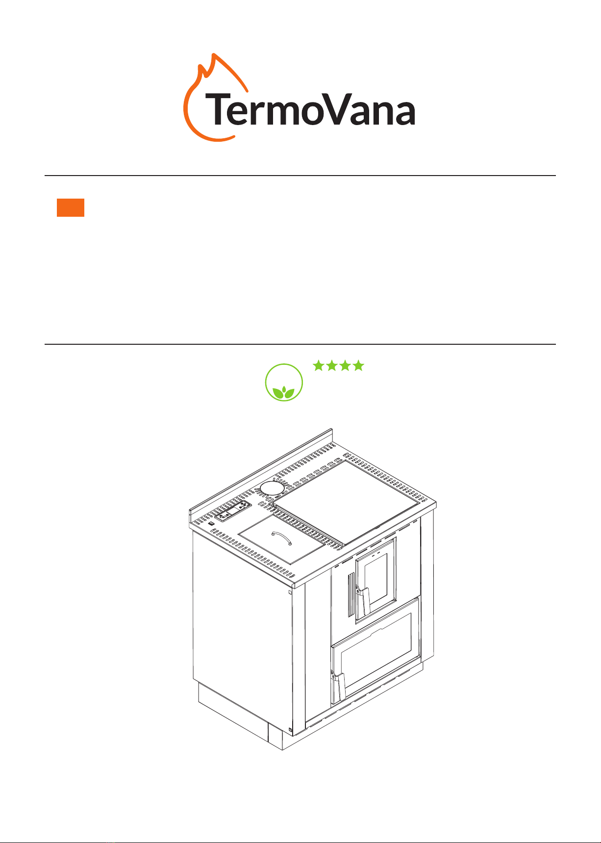
AIR PELLET COOKER
This product complies with the 4-star class
as per the emission and performance standards
of Italian Legislative Decree no. 186, 7th November 2017
ECO
DESIGN
2022
DESYRÉ 9.0

Alexa,
turn on
the stove
The stoves are supplied ready for the option-
al Wi-Fi module allowing the automatic man-
agement of functions through the Termovana
App available on Apple Store and Google
Play.
Or else through Amazon Alexa voice com-
mands, and coming soon, Google Home.
Download the Termovana App
and automatically manage
your stove by remote
Dear Customer,
we wish to thank you for choosing one of our products and we congratulate you on your choice.
In order to help you make the best use of your new stove, we invite you to carefully follow the instructions
provided in this manual.
EN

ENGLISH
ENGLISH
3
09/2020 - EN
INDEX
1 GENERAL INTRODUCTION > 4-6
1.1 SYMBOLS
1.2 DESTINATION OF USE
1.3 SCOPE AND CONTENTS OF MANUAL
1.4 STORAGE OF MANUAL
1.5 UPDATE OF THIS MANUAL
1.6 GENERAL INFORMATION
1.7 MAIN STANDARDS APPLIED AND TO BE APPLIED
1.8 LEGAL WARRANTY
1.9 MANUFACTURER'S LIABILITY
1.10 CHARACTERISTICS OF THE USER
1.11 TECHNICAL ASSISTANCE
1.12 SPARE PARTS
1.13 IDENTIFICATION PLATE
1.14 STOVE DELIVERY
2 SAFETY WARNINGS > 7-8
2.1 WARNINGS FOR THE INSTALLER
2.2 WARNINGS FOR THE MAINTENANCE TECHNICIAN
2.3 WARNINGS FOR THE USER
3 CHARACTERISTICS OF FUEL > 9
3.1 CHARACTERISTICS OF FUEL
3.2 STORAGE OF PELLETS
4 HANDLING AND TRANSPORT > 9
4.1 REMOVAL FROM TRANSPORT PALLET
5 INSTALLATION > 10-14
5.1 GENERAL CONSIDERATIONS
5.2 SAFETY PRECAUTIONS
5.3 PLACE OF INSTALLATION OF STOVE
5.4 COMBUSTION AIR
5.5 FLUE GAS EXHAUST PIPE
5.6 STOVE LEVELLING
5.7 CONNECTION TO UTILITIES
5.8 OPTIMISATION OF COMBUSTION
5.9 VENTILATION
6 MAINTENANCE > 15
6.1 MAINTENANCE
7 DEMOLITION AND DISPOSAL > 16
8 INITIAL DISPLAY CONFIGURATION > 17
8.1 CONNECTION TO AN EXTERNAL THERMOSTAT
9 CONTROL PANEL > 17-19
9.1 USE OF CONTROL PANEL
9.2 PROGRAMMING
9.3 DATE AND TIME
9.4 WEEKLY
9.5 PROGRAMME NUMBER
9.6 DAY OF THE WEEK
9.7 HOUR
9.8 MINUTES
9.9 TEMPERATURE
9.10 REQUESTED PROGRAMME
9.11 PROGRAMME TYPE
9.12 PROGRAMME ENABLING
9.13 EXAMPLE OF PROGRAMMING
9.14 THERMOSTAT MODE
9.15 INTERNAL THERMOSTAT
9.16 OPERATING PARAMETERS
9.17 PELLET LOADING
9.18 FLUE GAS EXTRACTION
9.19 ROOM FAN
9.20 RECENT ERRORS LOG.
9.21 LANGUAGE SELECTION
10 DIAGNOSTIC ERRORS > 20
10.1 ERROR 1 FAILED IGNITION
10.2 ERROR 2 FLUE GAS EXTRACTION MOTOR FAULT
10.3 ERROR 3 FLUE GAS EXTRACTION CIRCUIT FAULT
10.4 ERROR 4 NOT ACTIVE
10.5 ERROR 5 NO PELLETS
10.6 ERROR 6 PRESSURE SWITCH / THERMOSTAT ALARM
10.7 ERROR 7 NOT ACTIVE
10.8 ERROR 8 NO MAINS POWER
10.9 ERROR 9 FLUE GAS MOTOR ALARM
10.10 ERROR 10 OVERTEMPERATURE ALARM
10.11 ERROR 11 EXPIRY PASSED
10.12 ERROR 12 FLUE GAS PROBE
REMOTE CONTROL (OPTIONAL)
11 PRELIMINARY OPERATIONS > 21
11.1 PELLET LOADING
11.2 ELECTRICAL POWER SUPPLY
11.3 POWER ON
11.4 POWER OFF
11.5 OPERATION WITH AMBIENT PROBE ON STOVE
TROUBLESHOOTING > 22-23
12 CLEANING > 24-27
13 HOT AIR DUCTING > 28
14 COOKING METHODS > 29
ID PLATE KEY > 30
WIRING DIAGRAM > 31
DESCRIPTION > 32
TECHNICAL SPECIFICATIONS > 30-33
REMOVAL FROM PALLET > 34
MINIMUM DISTANCE FROM COMBUSTIBLE MATERIALS > 34
DIMENSIONS > 35
409/2020 - EN
1.3 SCOPE AND CONTENTS OF MANUAL
The scope of the manual is to provide the essential
and basic rules for the correct installation,
maintenance and use of the product. Strict
compliance with the instructions provided herein
ensures a high degree of safety and good operation
of the stove.
1.4 STORAGE OF MANUAL
This manual must be carefully stored and must
be available at all times for consultation, both
on the part of the user that the installation and
maintenance personnel.
The installation manual is an integral part of the
stove.
If necessary, request a further copy from Delka.
In the event of transferring the stove the user is
obliged to deliver even this manual to the new
owner.
1.5 UPDATE OF THIS MANUAL
Thismanualreectsthestateoftheartatthetime
of placing the stove on the market.
1.6 GENERAL INFORMATION
In case of exchange of information with the
Manufacturer of the stove, refer to the serial number
andidenticationdataindicatedontheproduct’s
serial number plate.
Extraordinary maintenance operations must be
performed by qualied personnel authorised to
intervene on the model of stove to which this
manual refers.
Delka cannot be held responsible for stove
installation works, which are and remain the
responsibility of the installer, who is also in charge
ofperformingthenecessaryinspectionsontheue
and air intake, as well as ensuring the correctness
of the proposed installation solutions. Furthermore,
allthesafetyregulationsprovidedforbythespecic
legislation in force in the state where the same is
installed must be observed.
Use of the stove is also subject, in addition to the
provisions contained in this manual, to compliance
withallthesafetystandardsrequiredbythespecic
legislation in force in the state where it is installed.
1 GENERAL INTRODUCTION
The product, subject of this manual, was
manufactured and tested according to the safety
requirements stated in the reference European
directives.
This manual is intended for stove owners,
installers, users and maintenance personnel of
the stove and is an integral part of the product.
In case of uncertainty about the content and for
anyclarication,contact themanufactureror the
authorised technical assistance service, stating the
number of the paragraph of the topic in question.
Even partial printing, translation and reproduction of
this manual are bound by the authorisation of Delka.
Technical information, graphical representations
and specifications in this manual may not be
disclosed to third parties.
Do not operate unless all information reported in this
manual has been perfectly understood; if in doubt,
always request the advice or intervention of Delka
specialised personnel.
Delka reserves the right to change specications
and technical and/or functional characteristics of
the stove at any time without prior warning.
1.1 SYMBOLS
In this manual the points of major importance are
highlighted by the following symbols:
INDICATION: Indications concerning the correct
use of the stove and the responsibilities of the
persons responsible.
ATTENTION: The point in which a note of particular
importance is expressed.
DANGER: Expresses an important note of
behaviour for the prevention of injuries or damage
to properties.
1.2 DESTINATION OF USE
Theproductreferredtobythismanualisarebox
for internal domestic heating, powered exclusively
by wood pellets with automatic operation.
The stove only works with the fire box door
closed.
The door must never be opened during stove
operation.
The appliance is not intended for use by persons
(including children) with reduced physical, sensory
or mental capacity, or without experience and
knowledge, unless they have received instructions
relating to the safe use of the appliance and they
are under the surveillance of a person responsible
for their safety.
Theintendedusespeciedaboveandthespecied
stovecongurationsaretheonlyonespermittedby
the manufacturer: only use the stove following the
instructions provided.

ENGLISH
ENGLISH
5
09/2020 - EN
1.7 MAINSTANDARDSAPPLIEDANDTOBE
APPLIED
A) Directive 2014/35/EU: “Electrical equipment
designedforusewithincertainvoltagelimits’.
B) Directive 2014/30/EU: “The approximation
of the laws of the Member States relating to
electromagnetic compatibility”.
C) Directive 89/391/EEC: “Implementation of
measures to encourage improvements in the
safety and health of workers at work”.
D) Regulation EU 305/2011: “Establishes
harmonised conditions for the marketing of
construction products and repeals Directive
89/106/EEC”.
E) Directive 1999/34/EC: “Concerning the
rapprochement of the laws, regulations and
administrative provisions of the member states
with regard to liability for damage caused by
defective products”.
F) Standard EN 14785/2006: Concerning
“Domestic heating appliances supplied with
wood pellets - Requirements and test methods”.
1.8 LEGAL WARRANTY
The user, in order to be able to take advantage of
the legal warranty, referred to in Directive 1999/44/
EC, must strictly observe the provisions contained
in this manual and in particular must:
• alwaysoperatewithinthestove’slimitsofuse;
• always carry out constant and diligent maintenance;
• authorise use of the stove by persons of proven
capacity, aptitude and who are adequately trained
for the purpose.;
• useoriginalsparepartsspecictothestovemodel.
1.8.1 THE FOLLOWING CIRCUMSTANCES ARE
EXCLUDED FROM THE WARRANTY:
• Improper overheating of the appliance, or use
of fuels not compliant with the type and quantity
indicated in the supplied instructions;
• Any parts found to be defective due to negligence or
careless use, incorrect maintenance or installation
that does not comply with the manufacturer’s
instructions (always refer to the installation and use
manual supplied with the appliance);
• Further damage caused by makeshift user
interventions in an attempt to solve the initial failure;
• Aggravation of damages caused by continued use
of the appliance by the user once the defect has
already been manifested;
• Damage caused by transport and/or handling;
• Inefficiency of chimneys, flues, or parts of the
system on which the appliance depends.
• Damage caused due to tampering with the device,
atmospheric agents, natural disasters, acts of
vandalism, electrical discharges, defects in the
electrical and/or water system.
• Failure to arrange for the annual cleaning of the
stove by an authorised technician or qualified
personnel, shall invalidate the warranty.
• Parts subject to normal wear such as gaskets, glass,
cast iron cladding and grilles, painted, chrome-
plated or gilded details, handles and electrical
cables, lamps, luminous indicators, knobs, all parts
thatcanberemovedfromtherebox;
• Colour variations of painted and or ceramic/coil
parts, as well as aws in the ceramic insofar as
these are natural characteristics of the material and
use of the product;
• Masonry works;
• Parts of the system (if included) not supplied by the
manufacturer.
1.8.2 WARRANTY TERMS:
The company guarantees the product, except
for elements subject to normal wear reported
below, for a period of 2 (two) years from the date
of purchase, which must be proven by:
• valid documentation (invoice and/or tax receipt)
showing the name of the vendor and date on which
the sale was made;
• theforwardingofthecompletedwarrantycerticate
within 8 days of the purchase;
• The term warranty implies the free replacement or
repair of parts recognised as defective at the origin
due to manufacturing defects;
• In order to claim under warranty, in the event of a
defectthebuyermustkeepthewarrantycerticate
and submit it together with the document issued at
the time of purchase, to the Technical Assistance
Centre;
Moreover, it is necessary to provide:
• a tax receipt with the date of purchase;
• acerticateofconformityoftheinstallationissued
by the installer;
Failure to comply with the requirements
contained in this manual will imply the immediate
cancellation of the warranty.
1.8.3 This warranty does not cover any malfunctions
and/or damage to the appliance due to the
following causes:
• Any technical interventions on the product to eliminate
the aforementioned defects and resulting damage;
these must be agreed upon with the Technical
Assistance Centre, which reserves the right to accept
or reject the relative claim, which in any case will
not be carried out under warranty, but rather in the
form of technical assistance provided in accordance
withanyconditions,specicallyagreedupon,andin
accordance with the rates in force for the works to be
carried out;
609/2020 - EN
• The user will also be responsible for any expenses
incurred to rectify their own makeshift technical
interventions, tampering, or in any case factors that
are damaging to the appliance and not attributable to
manufacturing defects;
• Without prejudice to the limits imposed by laws or
regulations, any guarantee of containment of airborne
and noise pollution is also excluded;
The company declines all liability for any
damage that may, either directly or indirectly,
as a consequence of the failure to comply with
any of the provisions contained in this manual,
in particular in regards to warnings for the
installation, use and maintenance of the appliance.
1.9 MANUFACTURER’S LIABILITY
With the delivery of this manual, Delka declines
all responsibility, both civil and criminal, direct or
indirect, due to:
• installation not complying with the existing
regulations in the country and with the safety
directives;
• partial or total non-compliance with the
instructions in this manual, in particular those
concerning the necessary routine cleaning;
• installation by unqualified and untrained
personnel;
• use not in compliance with the safety directives;
• modicationsandrepairsnotauthorisedbythe
Manufacturer on the stove;
• theuseofnon-originalornon-specicpartsfor
the stove model;
• insucientmaintenance;
• exceptional events.
1.10 CHARACTERISTICS OF THE USER
The user of the stove must be an adult and
responsible person having the knowledge needed
for routine maintenance of the stove components.
Make sure that children do not come close to the
stove, while it is running with the intent to play.
1.11 TECHNICAL ASSISTANCE
Delka provides a dense network of specialist
technical assistance centres, trained and prepared
directly at the company.
Theheadoceandoursalesnetworkisatyour
disposal to direct you to the nearest authorised
service centre.
1.12 SPARE PARTS
Use only genuine spare parts.
Do not wait until the components are worn by use
before proceeding to their replacement.
Replace a worn component before its breaking
favours the prevention of accidents arising from
accidents caused by the sudden breakage of
components which may cause serious damages
to persons and objects.
Perform periodic maintenance checks as indicated
in the “Maintenance” chapter.
1.13 IDENTIFICATION PLATE
The serial number plate on the stove shows all the
characteristic data relating to the product, including
theManufacturer’sdata,theserialnumberandthe
marking .
1.14 STOVE DELIVERY
The stove is delivered perfectly packed with
cardboard or heat-shrinkable sheet and secured to
a wooden platform that allows it to be moved using
forklift trucks and/or other means.
Inside of the stove there is the following material:
• instruction manual.
ENGLISH
ENGLISH
7
09/2020 - EN
2 SAFETY WARNINGS
2.1 WARNINGS FOR THE INSTALLER
Observe the prescriptions contained in this manual.
• The stove removal and installation instructions are
reserved to specialist technicians only.
• It is always recommended that users contact our
technical assistance service to request qualied
technicians. In the case other technicians are
involved, it is recommended to verify their actual
abilities.
• Responsibility for the works carried out in the
location of the machine is, and remains, attributable
to the user; the latter is also required to perform
checks on the proposed installation solutions.
• The user must comply with all local, national and
European safety regulations.
• Theappliancemustbeinstalledonoorswithan
adequate load bearing capacity.
Checkthattheueandairintakepredispositions
conform to the type of installation.
• Donotcarryoutyingelectricalconnectionswith
provisional or non-insulated cables.
• Check that the earthing of the electrical system is
ecient.
• It is prohibited to install the stove in bedrooms,
bathrooms and shower rooms, in rooms where
combustible materials are stored and in studio
apartments.
Installation is allowed in studio apartments only
with outside air intakes and if properly installed in
accordance with regulations;
• Under no circumstances can the stove be installed
in rooms where it is exposed to contact with water
or splashes of water, as this may cause the risk of
burns and short circuits.
• Inaccordancewithresafetylaws,theclearances
fromammableorheat-sensitiveobjectsmustbe
respected (sofas, furniture, wood cladding, etc.).
• Inthecaseofhighlyammableobjects(curtains,
carpet, etc.), all these clearances must be increased
by 1 metre.
2.1.1 WARNINGS FOR THE INSTALLER
The person in charge of the installation, before
starting assembling or disassembling of the stove,
must comply with the safety precautions required
by law and in particular:
A) do not operate in adverse conditions;
B) must operate in perfect psychophysical
conditions and must check that the personal
protective equipment, are intact and functioning
perfectly;
C) must wear safety gloves;
D) must wear safety shoes;
E) must use electrical insulated tools;
F) must ensure that the area affected by the
phases of assembly and disassembly is free
from obstacles.
2.2 WARNINGS FOR THE MAINTENANCE
TECHNICIAN
Observe the prescriptions contained in this manual.
• Always use individual safety devices and other
means of protection.
• If the oor is made of combustible material, it
is recommended to use protection in a non-
combustible material (steel, glass) that also protects
the front part in the event of any fuel spills during
cleaning operations.
• Before starting any maintenance operation, make
sure that the stove has cooled down if it has been
used.
• If even one of the safety devices is found to be
derated or not functioning, the stove should be
considered as not functioning.
• Non-specialised users must be prevented from
accessing any parts that may expose them to
dangers. This person must therefore not be allowed
to intervene on internal parts at risk (electrical
or mechanical), even if the power needs to be
disconnected
• Disconnect the power supply before working on
electrical and electronic parts and connectors.
2.3 WARNINGS FOR THE USER
Do not touch and do not approach the door glass
as it could cause burns;
• Donotlookattheameforalongtime;
• Donottouchtheuegasexhaustpipe;
• Do not dispose of hot ash (ensure it is completely
extinguished and cooled before vacuuming or
removing it);
• Do not open the glass door;
• Do not open the ash drawer (where provided);
• Do not touch and do not approach the glass of the
door, it could cause burns;
• Donotlookattheameforalongtime;
• Donottouchtheuegasexhaustpipe;
• Do not perform any type of cleaning;
• Do not dispose of hot ash (ensure it is completely
extinguished and cooled before vacuuming or
removing it);
• Do not open the glass door;
• Do not open the ash drawer (where provided);
• Do not use the appliance as a waste incinerator.
• It is prohibited to operate the product with the door
open or the glass broken.
• It is prohibited to make unauthorised changes to
the appliance.
• Do not use flammable liquids during ignition
(alcohol, benzene, oil, etc.).
• After a failed ignition attempt, the accumulated
pellets must be emptied from the burn pot before
igniting the stove again.
• The pellet tank must always be closed with the lid on.

809/2020 - EN
• Before performing any type of operation, wait for
theameinthecombustionchambertofullydrop
until it is completely extinguished and cooled, and
always detach the plug from the power socket.
• Before performing any type of operation, the user
or whoever is operating the product must have read
and fully understood the contents of this installation
and use manual. Errors or bad settings may cause
hazardous conditions and/or irregular operation.
• The only type of fuel that can be used is pellets.
• Do not place laundry on the product to dry. Any
clotheslines or similar must be kept at a suitable
distance from the product. Fire hazard.
• The electrical cord must never come into contact
withtheuegasexhaustpipeoranyotherpartof
the stove.
• Packaging materials are NOT toys, they may
cause asphyxiation or choking risks and other
health hazards! Persons (including children) with
reduced physical or motor skills, or who are lacking
the necessary experience and knowledge, must be
kept away from the packaging. The stove is NOT a
toy.
• Children must be constantly supervised to ensure
they do not play with the appliance.
• Cleaning and maintenance must be performed
by the user and cannot be carried out by children
without supervision.
• During operation, the stove reaches high
temperatures: keep out of reach of children and
animals and use ame-proof personal protective
equipment suitable to protect against the heat.
• If the oor is made of combustible material, it
is recommended to use protection in a non-
combustible material (steel, glass) that also protects
the front part in the event of any fuel spills during
cleaning operations.
2.3.1 WARNINGSANDRECOMMENDATIONSFORTHE
USER
• Observe the prescriptions contained in this manual.
• Respect the instructions and warnings highlighted
by the plates displayed on the stove.
• The plates are safety devices, therefore they must
always be perfectly legible. If these are damaged
and unreadable, it is mandatory to replace them,
requesting the original spare parts from the
Manufacturer.
• Use only the fuel complying with the indications given
in the chapter relating to the fuel characteristics.
• Follow the routine and extraordinary maintenance
schedule carefully.
• Donotusethestovewithoutrstperformingthe
daily inspection as prescribed in the “Maintenance”
chapter of this manual.
• Do not use the stove in case of abnormal operation,
suspicion of breakage or unusual noises.
• Do not throw water on the stove in operation or with
theintentionofextinguishingthereintheburnpot.
• Donot switcho thestove by disconnectingthe
mains electrical connection.
• Do not lean on the open door, it could compromise
its stability.
• Do not use the stove as a support or anchor of any
kind.
• Do not clean the stove until the structure and the
ashes have completely cooled down.
• Only touch the door when the stove is cool.
• Perform all operations in maximum safety and when
calm.
Incaseofare,contacttherebrigade.
In the event of stove malfunction due to non-optimal
flue draught, clean it following the procedure
described.
Theuemustbecleanedasdescribedinparagraph
6.
Do not touch the painted parts during operation to
avoid damage to the paintwork.

ENGLISH
ENGLISH
9
09/2020 - EN
3 CHARACTERISTICS OF FUEL
3.1 CHARACTERISTICS OF FUEL
Thepellet(g.3.1)iscomposedofvarioustypes
of wood, compressed using mechanical processes
in accordance with environmental protection laws
and is the only type of fuel intended for this type of
stove.
Theeciency andthermal potentialof thestove
may vary depending on the type and quality of the
pellets used.
We recommend the use of class A1 pellets
(ISO 17225-2, ENplus A1, DIN Plus or NC 444
category “High Performance NF Pellets Biofuels
Quality”).
The stove is equipped with a pellet holding tank
having the capacity indicated in the technical
specicationstableinsection14.
The loading compartment is positioned in the upper
part. It must always be openable in order to load
the pellets and must remain closed during stove
operation.
For reasons of operating temperature control
traditional wood operation is not possible.
It is forbidden to use the stove as a waste
incinerator.
3.2 STORAGE OF PELLETS
The pellets must be stored in a dry environment
where the temperature is not too cold.
It is recommended to keep a few bags of pellets in
the room where the stove is used, or in a nearby
place provided the temperature and humidity are
acceptable.
Wet and/or cold pellets (5°C) reduce the thermal
potential of the fuel resulting in the need for more
cleaning maintenance of the burn pot (unburned
material)andoftherebox.
Pay particular attention to the storage and handling
of pellet bags. Their crushing and the formation of
sawdust must be avoided.
Ifsawdustisintroducedintothestove’stank,this
could cause the pellet loading system to become
blocked.
Keep the fuel at a safe distance from the stove.
The use of poor quality pellets can compromise the
normal operation of the pellet stove and result in
forfeiture of the warranty.
4 HANDLING AND TRANSPORT
The stove is delivered complete with all the parts
provided.
Pay attention to the tendency to unbalance the
stove.
The centre of gravity of the stove is moved towards
the front.
Bear in mind the above also when moving the stove
on the transportation support.
During lifting, avoid jerking or abrupt movements.
Make sure the forklift truck has a capacity greater
than the weight of the stove to be lifted.
The full responsibility of the lifting of loads lies on
the person handling the lifting equipment.
Make sure that children do not play with the
components of the packaging (e.g. films and
polystyrene).Dangerofsuocation!
4.1 REMOVALFROMTRANSPORTPALLET
To remove the stove from the transport pallet,
follow the instructions on page 34.
g.3.1
10 09/2020 - EN
5 INSTALLATION
5.1 GENERAL CONSIDERATIONS
In the following paragraphs there are some
guidelines to follow in order to obtain the maximum
performance of the product purchased.
The following instructions are nevertheless subject
to compliance with any laws and national, regional
and municipal regulations in force in the country
where the product is installed.
Installation must be performed by qualified
personnel in compliance with the UNI 10683
standard.
5.2 SAFETY PRECAUTIONS
The responsibility of the works carried out in the
area where the stove will be installed falls, and
remains, on the user; the latter is also entrusted
with the execution of the inspections related to the
installation solutions proposed.
The user must comply with all local, national and
European safety regulations.
The appliance must be installed on oors with
adequate load bearing capacity.
The stove removal and installation instructions must
only be performed by specialist technicians. It is
always recommended that users contact our after
saleservicetorequestqualiedtechnicians.
In the case other technicians are involved, it is
recommended to verify their actual abilities. The
person in charge of the installation, before starting
assembly or disassembly of the stove, must comply
with the safety precautions required by law and in
particular with:
A) do not operate in adverse conditions;
B) must operate in perfect psychophysical
conditions and must check that the personal
protective equipment, are intact and functioning
perfectly;
C) must wear safety gloves;
D) must wear safety shoes;
E) must use electrical insulated tools;
F) must ensure that the area affected by the
phases of assembly and disassembly is free
from obstacles.
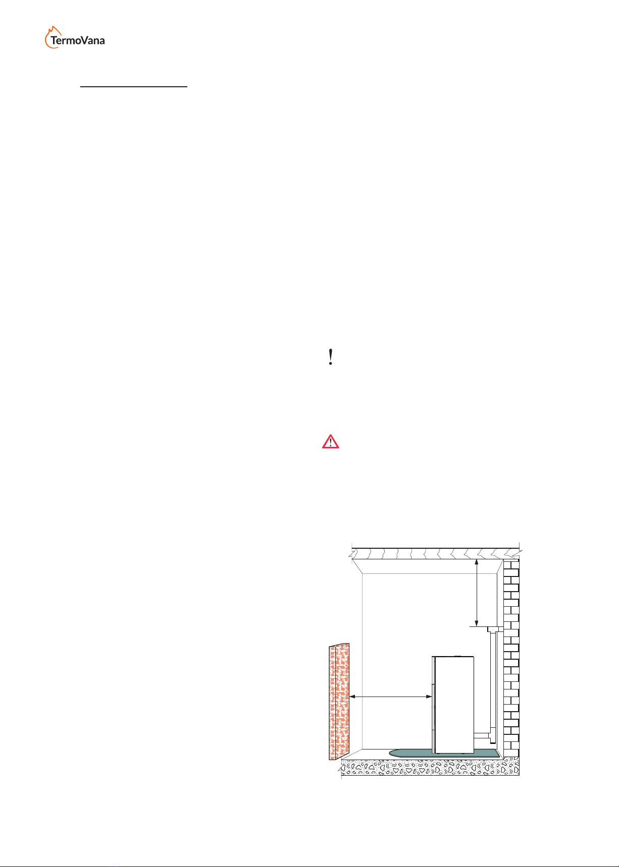
5.3 PLACE OF INSTALLATION OF STOVE
On page 34of this manual, the minimum
clearances are shown, expressed in cm,
which must be respected when positioning the
stove with respect to combustible materials and
objects.
Protect all structures which could ignite if exposed
to excessive heat.
Floorsconsistingofflammablematerialsuchas
for example: wood, parquet, linoleum, laminate or
coveredwithcarpets,mustbeprotectedbyaflame
retardant base under the stove, of a sufficient
size. This base can be, for example, in steel,
pressed slate,glassorstoneandmustcoverthe
floor in the area below the stove and the flue
connectingpipeand must protrude at least 50 cm
in front.
The manufacturer declines all responsibility for
any variations in the characteristics of the material
constitutingthefloorundertheprotection.
Any wooden elements (e.g. beams) or combustible
materials located near the stove must be protected
withfireproofmaterial.
Flammable walls or elements must be kept at a
distance of at least 150 cm from the stove.
Provide a technical space accessible for possible
maintenance.
Remember to respect the minimum clearance from
flammablematerials(x)shownontheIDplateof
thepipesusedforthechimney(fig.5.2).
Pi = Flammable wall
Pp = Floor protection
It is prohibited to install the stove in bedrooms,
small rooms and environments having potentially
explosive dusts in the atmosphere.
Fig. 5.2
Pi
Pp
Pi
X
80 cm
Product images are purely indicative
ENGLISH
ENGLISH
11
09/2020 - EN
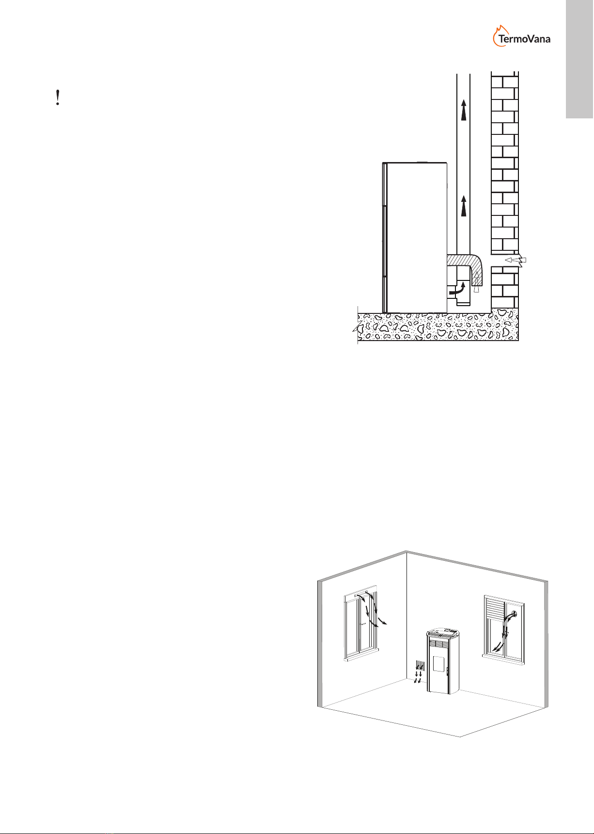
5.4 COMBUSTION AIR
During use, the stove withdraws a certain quantity
of air from the environment where it is located
(except for products in the hermetic series, which
can withdraw air directly from the outside); this air
must be reintegrated through an external air intake
(g.5.3-PA=AirIntake).
If the rear wall of the stove is an external wall,
create a hole for suction of the combustion air at a
height of approximately 20-30 cm from the ground,
respecting the dimensional indications provided
in the product technical sheet at the end of the
manual.
A non-closable permanent aeration grid must be
placed external; in areas that are particularly windy
and exposed to weathering, provide rain and wind
protection.
Make sure the air intake is positioned so that it is
not accidentally obstructed.
If it is impossible to create the external air intake
in the rear wall of the stove (non-perimeter wall) a
hole must be created in an external wall of the room
where the stove is positioned.
If it is not possible to create the external air intake
in the room, an external hole can be created
in an adjacent room provided it communicates
permanentlywithatransitgrille.(g.5.4-C=Box,
G = Grille, S = Shutter)
The UNI 10683 standard prohibits the taking of
combustion air from garages, combustible material
warehousesoractivitieswiththeriskofre.
If there are other heating appliances in the room,
the combustion air intakes must guarantee the
necessary volume of air for correct operation of all
the devices.
In the event that one or more extraction fans
(suction hoods) are present and functioning in
the room where the stove is located, combustion
malfunctions due to the lack of combustion air could
occur.
g.5.4
C
G
S
g.5.3
PA
PA
Product images are purely indicative
12 09/2020 - EN
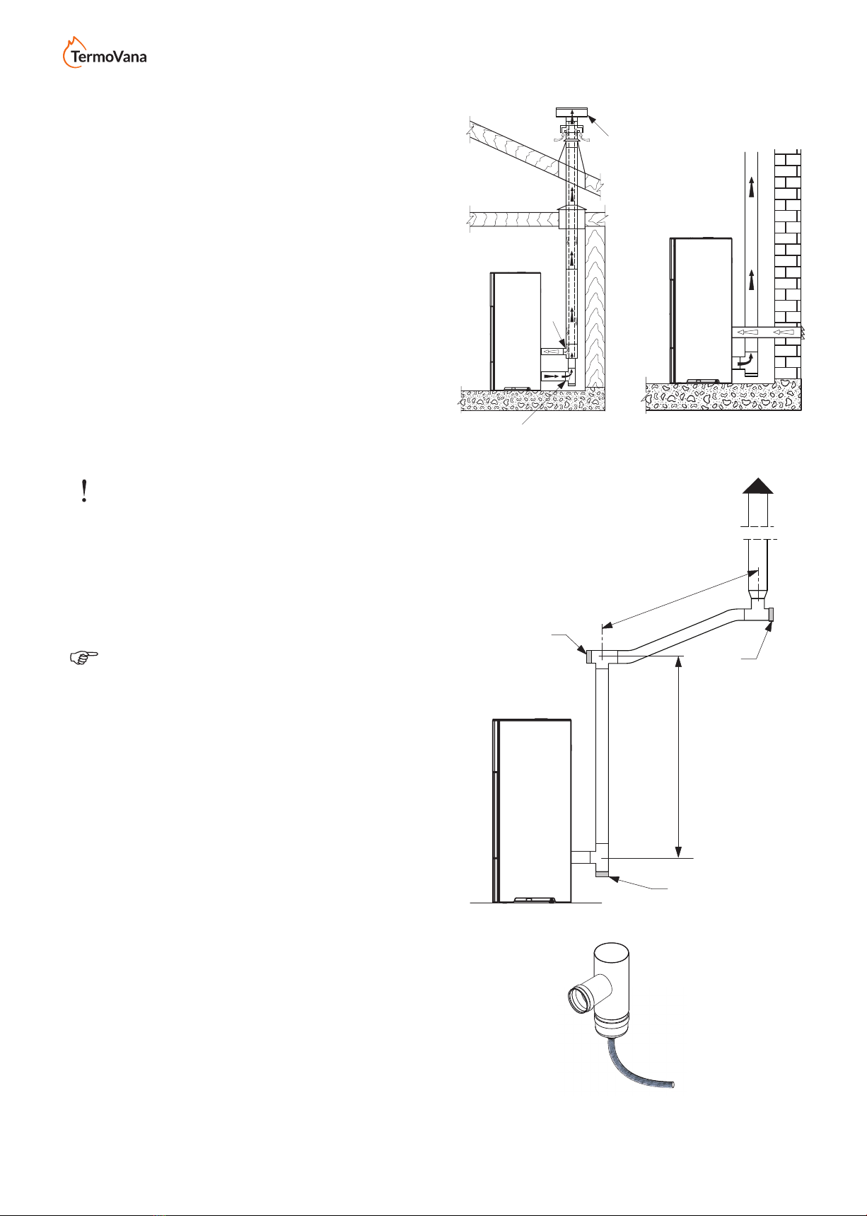
If a pellet stove in the “Hermetic” series is installed,
alternatively it is possible to:
- channel the combustion air using a coaxial
exhaustpipefortheexpulsionoftheuegases
and air withdrawal; therefore it is not necessary
tocreateaclassicairintakeintheroom(g.
5.5 A,B = Air inlet C,D = Flue gas outlet);
- connectthestove’scombustibleairinlettothe
airintakewithasuitableduct(g.5.6).
5.5 FLUE GAS EXHAUST PIPE
The stove works with the combustion chamber in a
vacuum,thereforeitisessentialtoensuretheue
gas exhaust pipe is properly sealed.
The stove must be connected to its own dedicated
flue system, suitable in ensuring the proper
dispersion of the combustion products in the
atmosphere.
The components that make up the ue system
mustbedeclaredsuitableforthespecicoperating
conditions and provided with CE marking.
Itismandatorytocreatearstverticalsectionofa
minimum 1.5 meters to guarantee correct expulsion
oftheuegases.
It is advisable to make a maximum of 3 changes
of direction, in addition to that resulting from the
rear connection of the stove to the chimney, using
45-90°bendsorT-ttings(g.5.7).
Always use a T-tting with an inspection cap at
each horizontal and vertical variation of the ue
gas exhaust pipe.
OntherstT,attheexitoftheuegasoutletof
the stove, it is necessary to connect a pipe at the
bottom in order to evacuate any condensate that
may form in the chimney (Fig. 5.7a).
The horizontal sections must have a maximum
lengthof2-3mwithanupwardslopeof3-5%(g.
5.7).
Anchor the pipes with suitable collars to the wall.
TheuegasexhaustconnectionMUSTNOTbe
connected:
- to a chimney used by other generators (boilers,
stoves,replaces,etc.);
- to air extraction systems (hoods, vents, etc.)
even if “intubated”.
Itisforbiddentoinstallshut-oanddraughtvalves.
The exhaust of the combustion products must be
provided on the roof.
Fig. 5.7a
Fig. 5.7
Fig. 5.5 Fig. 5.6
B
B
B
MAX 2 - 3 m
C > 3 - 5%
min 1,5 m
Product images are purely indicative
ENGLISH
ENGLISH
13
09/2020 - EN
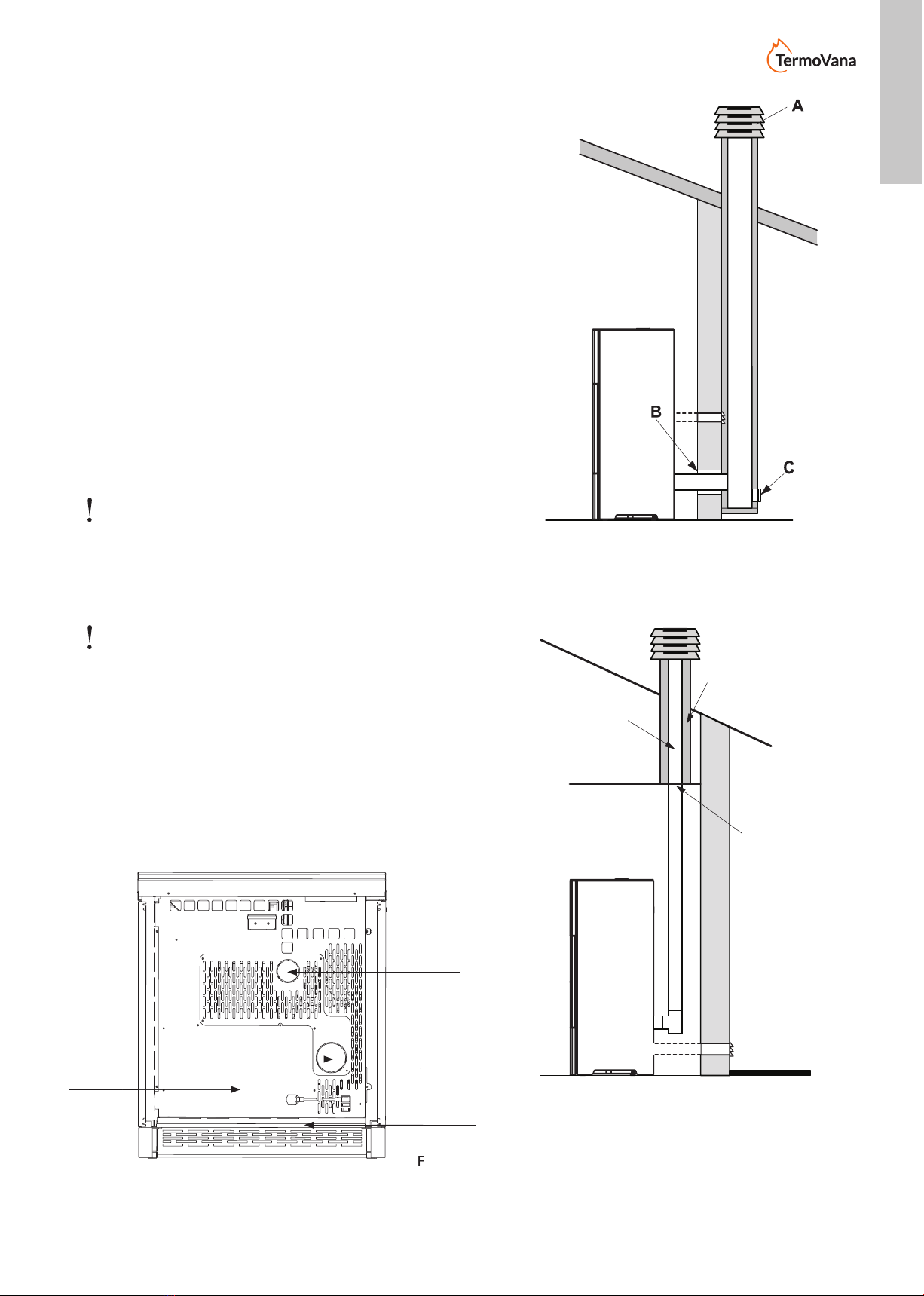
If a pellet stove in the “Hermetic” series is installed, it
ispossibletouseaspeciccoaxialpipethatallows
boththeexpulsionofuegasesandtheductingof
thecombustionairfromtheoutside(g.5.5A,B=Air
inlet C,D=Flue gas outlet).
5.5.1 Roof exhaust with traditional chimney
Theueforthe expulsionofue gases mustbe
developed in compliance with the UNI 10683- EN
1856-1-2- EN 1857- EN 1443- EN 13384-1-3- EN
12391-1 standards both regarding the dimensions
and the materials used in its construction.
DILAPIDATED chimneys, made with unsuitable
materials (brocement, galvanized steel, etc...
with rough and porous internal surfaces) are not
allowed and compromise the proper operation of
the stove.
Flue gases can be released through a traditional
chimney (Fig. 5.8) provided the proper
maintenance of the chimney is guaranteed;
For chimneys with a larger section, it is necessary
to “intubate” the chimney with steel piping (of
a diameter based on the path), which must be
properlyinsulated(g.5.9).
Check that the connection to the chimney in
masonry is properly sealed.
In case of pipes that pass through wooden roofs
orwalls,itisrecommendedtousespecialcertied
ducting kits commonly available on the market.
A) Windproof chimney stack
B) Seal
C) Inspection
1) Vermiculite and/or rock wool.
2) Steel piping.
3) Closing panel.
Fig. 5.8
Fig. 5.9
Fig. 5.5.2
1
2
3
Product images are purely indicative
Flue Gas
Outlet Extraction
primary air
Fig. 5.5.2
Flue Gas
Fig. 5.5.2
Extraction
primary air

14 09/2020 - EN
5.6 STOVE LEVELLING
The stove must be levelled, with the help of a spirit
level,byregulatingtheadjustablefeet(ifincluded)g.
5.10).
A B = Spirit Level
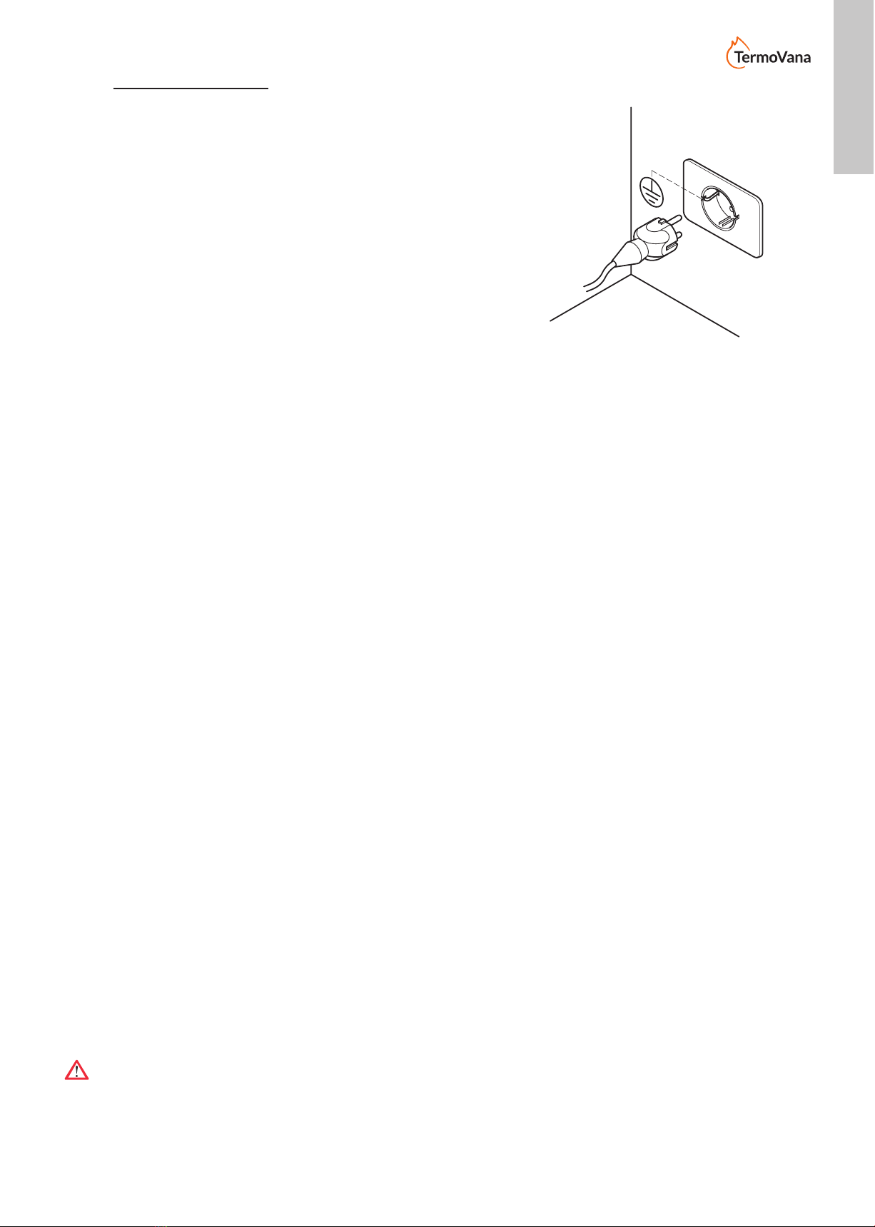
5.7 CONNECTION TO UTILITIES
5.7.1 Electrical connection
It is sucient to connect the stove to the electrical
system using the supplied plug.
The electrical connection (plug) must be easily
accessible even after installing the stove.
If the power cord is damaged, it must be replaced
bythetechnicalassistanceserviceorbyaqualied
technician in order to prevent any risk.
5.7.1.1 Earthing
The system must be earthed and equipped with a
dierentialswitchinaccordancewithlegislationinforce
(g.5.11).
Make sure the power cord does not come into contact
with hot parts.
The ue gas exhaust pipe must have its own earth
connection.
5.8 OPTIMISATION OF COMBUSTION
Best combustion depends on a variety of factors (type
of installation, operating and maintenance conditions,
type of pellets, etc...)
Upontherstignition,thestove’scombustioncanbe
optimised.
Generally speaking, if there is a lot of residue in the
burn pot at the end of combustion, it is recommended
toadjustthecombustionconguration(increasingthe
value) until the most suitable solution is found.
See sections 9.17- 9.18 - 9.19.
5.9 VENTILATION
The stove is equipped with ventilation.
The air pushed by the fans keeps the appliance at
a low enough temperature, thus avoiding excessive
stress on the materials of which it is composed.
Do not close the hot air outlet vents with any objects
or the stove will overheat!
ATTENTION: Do not cover the air vents.
Fig. 5.10
Product images are purely indicative
ENGLISH
ENGLISH
15
09/2020 - EN
6 MAINTENANCE
(by an authorised technical assistance centre)
6.1 MAINTENANCE
Maintenance operations must be performed by an authorised
technical assistance centre.
Before performing any maintenance operation, take the
following precautions:
- Make sure that all the parts of the stove are cold.
- Make sure that the ashes are completely extinguished.
- Use personal protective equipment provided for by Directive
89/391/EEC.
- Makesurethatthegenerallineswitchisturnedo.
- Make sure that the power supply cannot be accidentally
reactivated. Remove the plug from the wall socket.
- Always use appropriate equipment for maintenance.
- Once the maintenance or the repair operations are
completed, before re-commissioning the stove, install again
all the protections and restart all the safety devices.
6.1.1 FLUE SYSTEM MAINTENANCE
To be performed at least once a year, or every 40 tons of burned
pellets.
If there are horizontal sections, it is necessary to check and
remove any ash and soot deposits before they block the
passageoftheuegases.
In the event of failure or inadequate cleaning, the stove may
have functional problems such as:
- bad combustion
- glass blackening
- blockage of the burn pot with accumulation of ash and pellets
- riskofuecatchingre.
6.1.2 STOVE MAINTENANCE
It must be carried out at least once a year, or each time the
stove indicates that maintenance is required.
During the maintenance operation, the technician must:
- cleantheuegaspassageareathoroughlyandcompletely;
- check the condition of all the seals and make sure they work
properly;
- check the condition of all internal components and make
sure they are clean;
- makesuretheuegasoutletconnectionissealedandclean;
- remove any deposits of pellet residues in the tank;
- make sure that the stove is working properly;
- reset any warnings or alarms
6.1.3 GASKET REPLACEMENT
Ifthegasketsoftheredoor,tankoruegaschamberbecome
worn, they must be replaced by an authorised technician in
order to guarantee the proper operation of the stove.
ATTENTION: Use only original spare parts.
Fig. 5.11
Product images are purely indicative
16 09/2020 - EN
(*) By an authorised technical assistance centre.
(a) At least once a year or every 4 tonnes of burnt pellets.
7 DEMOLITION AND DISPOSAL
Demolition and disposal of the stove is the exclusive responsibility of the owner who must act in compliance with
the laws on safety, respect and protection of the environment, in force in the country where the stove is installed.
Decommissioning and disposal can be entrusted to a third party, provided to always use companies authorised
for recovery and elimination of the materials in question.
INDICATION: follow always and in any case the regulations in force in the country of installation for the disposal
of materials and possibly for the disposal report.
ATTENTION: All disassembly operations for the demolition must take place with the stove off and the power
supply disconnected.
• remove the entire electric system;
• separate the accumulators in the electronic cards;
• the stove structure can only be demolished by authorised companies;
ATTENTION: The abandonment of the stove in accessible areas constitutes a serious danger for people and
animals.
Any liability for damage to people and animals always falls on the owner.
At the time of demolition the CE marking, this manual and any other documents relating to this stove should be
destroyed.
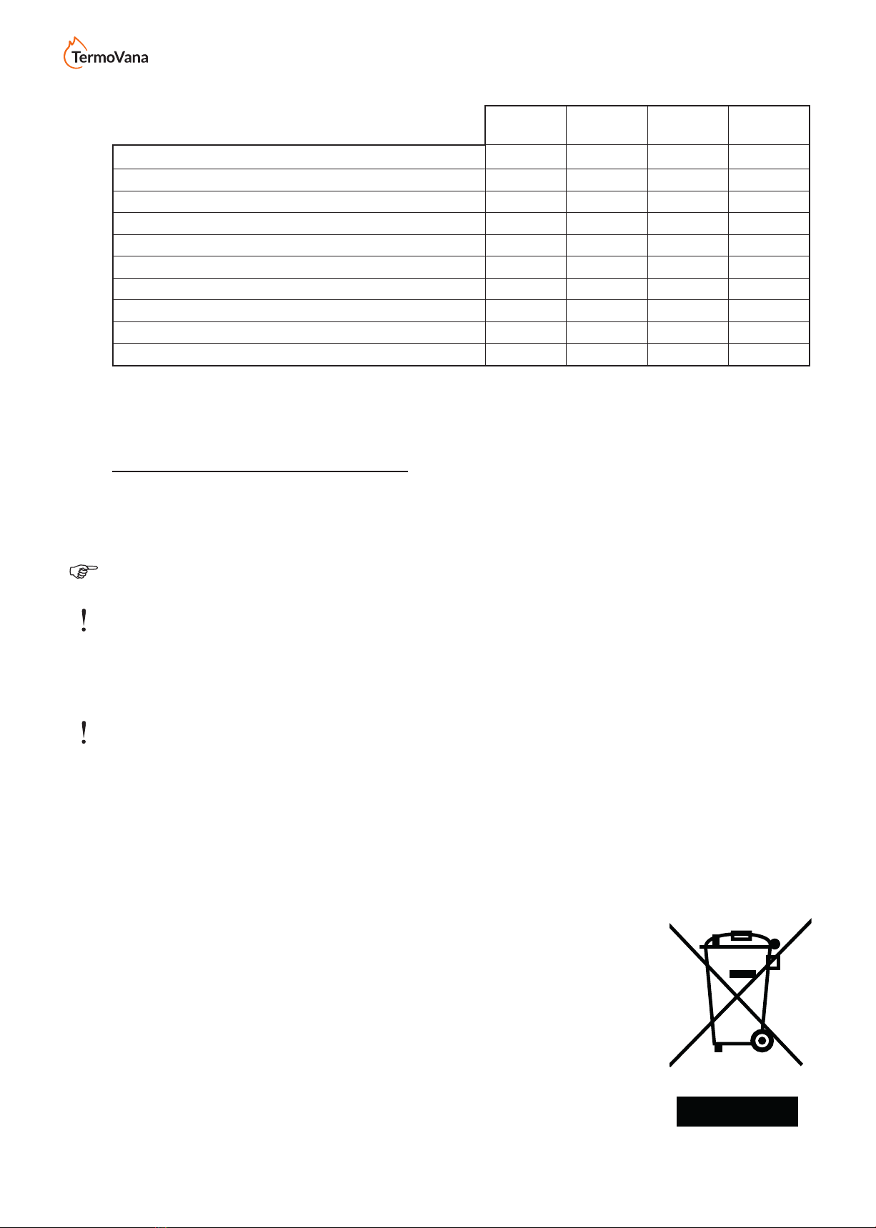
The crossed out wheelie bin symbol that appears on the label of the appliance indicates that the product at the
end of its useful life must be disposed of separately from other waste.
Within the meaning of art.13 of Legislative Decree no. 151 of 25 July 2005 implementing
the Directive 2002/96/EC of 23 February 2003 on Waste Electrical and Electronic
Equipment relating to the measures and procedures designed to prevent the production
of waste electrical and electronic equipment, called WEEE, promoting the reuse,
recycling and other forms of recovery so as to reduce the quantity to be disposed of
and improving the intervention of the parties involved in the life cycle of such products.
EACH
IGNITION
EACH
WEEK
1
MONTH
1
YEAR (y)
BURN POT X
ASH DRAWER X
GLASS X
ROOM FAN EXTRACTION GRILLE X
BOILER X
HEATING ELEMENT SLEEVE X
EXHAUST MANIFOLD X
DOOR AND BURN POT GASKETS* X
FLUE DUCT* X
FANS* X
CONTROL AND MAINTENANCE
PROGRAMME

ENGLISH
ENGLISH
17
09/2020 - EN
8 INITIAL DISPLAY CONFIGURATION
When the stove is turned on, the display shows the operating status. During the initial start-up, the display shows
thestovemodelandtheinstalledrmwarerelease.
The stove must be powered using the ON/OFF safety switch located at the back; after a few seconds it is ready
for ignition.
The stove will modulate its power based on the set ambient temperature, which is detected by the probe on-
board the stove.
8.1 CONNECTION TO AN EXTERNAL THERMOSTAT
Function not active in this version.
9 CONTROL PANEL
A D F
BH
C E G
I
A - SET User Menu
B - AUTO to enable the weekly programmer
C - ON/OFF and exit from Menu functions
D - Temperature setting + and menu functions
D - Temperature setting – and menu functions
F - Heating programme setting+ and menu functions
G - Heating programme setting – and menu functions
H - Remote control infra-red sensor
I - Alphanumeric 16x2 LCD Display
9.1 USE OF PANEL
Press SET (A) to open the user menu. Scroll the menu using the keys and .
Toopenthesubmenu,conrmusingthe SET (A) key.
1 - Set Date and Time
2 - Weekly programmer setting
3 - Thermostat mode
4 - Stove parameters
5 - Error log
6 - Language selection
7 - Fuel selection
EACH
IGNITION
EACH
WEEK
1
MONTH
1
YEAR (y)
BURN POT X
ASH DRAWER X
GLASS X
ROOM FAN EXTRACTION GRILLE X
BOILER X
HEATING ELEMENT SLEEVE X
EXHAUST MANIFOLD X
DOOR AND BURN POT GASKETS* X
FLUE DUCT* X
FANS* X

18 09/2020 - EN
9.2 PROGRAMMING
User programming is possible through the menu,
which can be opened by pressing the SET key on
the illuminated display panel. To exit the menu at
any time without making any changes, press the
STOP key. In any case, if the keys are not pressed
for about 1 minute, the system will automatically
exit the menu to show the stove status. To scroll
the various menus use the TEMP+ and TEMP-
keys, to open the displayed menu, press SET.
9.3 DATE AND TIME
SET DATE-TIME
Press SET to open the incorporated calender
setting menu. The day of the week can be
changed from Monday to Sunday, as well as the
time and date. To switch between the variables,
use the PROG+ and PROG- keys, and to change
the values, use the TEMP+ and TEMP- keys. To
conrmthechangesandexit,presstheSETkey.
9.4 WEEKLY
We 19 : 04
14/04/11
WEEKLY PROG
The programmer is only active in the automatic
operating mode (AUTO on the display).
There are 15 settable programming levels for
on and o times, the temperature and operating
programme. Each single programme can be
disabled without needing to be cancelled, following
a very simple procedure.
Press SET to open and scroll the various
programmes, or the TEMP+ and TEMP- keys to
scroll the variables to be changed. Then use the
PROG+ and PROG- keys to set the requested
values.
9.5 PROGRAMME NUMBER
F01 MF 08 : 00 20o
P4 On Enab.
Indicates the selected programme, from 1 to 15.
9.6 DAY OF THE WEEK
Indicates the day of the week of the displayed
programme. A setting can be made for each day,
from Monday to Sunday (Mo,Tu,We,Th,Fr,Sa,Su)
or else for all work days from Monday to Friday
(MF), or else for weekends from Saturday to
Sunday (SS). This system allows the setting of a
singleprogrammetoturnthestoveonoroevery
day, from Monday to Friday, at the same time.
9.7 HOUR
Stoveonorohour.
9.8 MINUTES
Stoveonorominutes.
9.9 TEMPERATURE
For ignition programmes, the requested ambient
temperature must be set between 5 and 30°C.
9.10 REQUESTED PROGRAMME
For ignition programmes, the requested heating
programme must be set between 1 and 5.
9.11 PROGRAMME TYPE
Seteitheranignitionprogramme,ON,orpowero
programme, OFF.
9.12 PROGRAMME ENABLING
This function is essential, because if in the disabled
position (No A.) the system will not control the
programme and the programme function may not
be executed.
9.13 EXAMPLE OF PROGRAMMING
To programme the stove so that it turns on every
day from Monday to Friday at 8am at level 4, with
a temperature of 20°C, proceed as follows after
opening the ignition programme setting.
With TEMP+ select MF as the ignition days from
Monday to Friday.
Select the Hour using the PROG+ key and set 08
with the TEMP+ and TEMP- keys.
Select the minutes using the PROG+ key and set
00 with the TEMP+ and TEMP- keys.
Select the temperature using the PROG+ key and
set 20° with the TEMP+ and TEMP- keys.
Select the heating power using the PROG+ key
and set 4 with the TEMP+ and TEMP- keys.

ENGLISH
ENGLISH
19
09/2020 - EN
Select the mode using the PROG+ key and set
ON with the TEMP+ and TEMP- keys.
Select the programme type using the PROG+ key
and set Enab. with the TEMP+ and TEMP- keys.
Press SET to save the data and insert a new
ignition programme. If programming is complete,
press STOP to exit.
Remember to set the operating mode to Automatic
to enable control of the weekly programmer.
9.14 THERMOSTAT MODE
THERMOSTAT MODE
Press SET to open and modify the operating mode
for temperature control or automated ignition and
powero.
9.15 INTERNAL THERMOSTAT
Operating mode that regulates stove operation
based on the detected ambient temperature. The
stove is ignited both manually and automatically
by the settings of the incorporated weekly
programmer or internal timer. The stove power
is automatically controlled based on the set
temperature, optimising heating with signicant
pellet savings.
9.16 OPERATING PARAMETERS
STOVE PARAMETERS
Press SET to open and modify the main stove
parameterssuchaspelletload,uegasextraction
speed, ambient air fan and ambient temperature
correction. Using the TEMP+ and TEMP- keys it is
possible to change the stove setting percentages
to correct its operation based on the pellets
used. Then press SET to conrm the modied
parameter and save it in the memory. Use the
PROG+ and PROG- keys to scroll the parameters.
Press the STOP key to exit the menu.
If the stove is in “Pellet Tuning” automatic mode,
the user will not be able to modify the pellet load
anduegasextractionspeedbecausethisis
automatically managed by the printed circuit
board.
9.17 PELLET LOADING
Allows all loading parameters to be increased or
decreased in percentage from -50 to +50%.
9.18 FLUE GAS EXTRACTION
Allows all ue gas extraction parameters to be
increased or decreased in percentage from -50 to
+50%.
9.19 ROOM FAN
Allows all air ventilation parameters to be increased
or decreased in percentage from -50 to +50%.
9.20 RECENT ERRORS LOG.
The menu allows the most recent errors recorded
by the printed circuit board to be viewed, along
with the date and time of the event, as well as a
brief description.
9.21 LANGUAGE SELECTION
SEL. LANGUAGE
English
The menu allows the user to select the language
of the panel messages:
Italian
English
French
German
Spanish
Using the PROG+ and PROG- keys it is possible
to scroll the various languages and select the
desired one.

20 09/2020 - EN
10 DIAGNOSTIC ERRORS
During operation, if a fault is detected the stove
turnso,followingthecoolingcycle,andanerror
message is shown on the display, which can
only be eliminated manually. Even if in automatic
operating mode, the stove waits for the alarm
reset command indicating that the fault has been
acknowledged. Following is a list of the possible
errors:
10.1 ERROR 1 FAILED IGNITION
If after an ignition cycle, the stove does not reach
the minimum operating temperature, the cycle
ends with an error and the system proceeds with
scheduled cooling. This may be due to a lack of
fuel, dirty burn pot or dirty or defective igniter.
Before re-igniting, check the burn pot, clean it if
necessary and empty any pellets therein.
10.2 ERROR 2 FLUE GAS EXTRACTION
MOTOR FAULT
Ifduringoperation, theue gasextractionmotor
does not maintain the programmed speed, the
cycle ends with a system error and proceeds
with scheduled cooling. (only if extraction sensor
included).
10.3 ERROR 3 FLUE GAS EXTRACTION
CIRCUIT FAULT
Ifduringoperationthesystemdetectsinsucient
air extraction, the cycle ends with a system error
and proceeds with scheduled cooling. This error
is common for use with both a pressure gauge
and extraction sensor (only if extraction sensor
included).
10.4 ERROR 4 NOT ACTIVE
10.5 ERROR 5 NO PELLETS
If during operation the combustion chamber
temperature drops below the set limit. The cycle
ends with a system error. This may be due to a
lack of fuel or the blocked distribution of the fuel.
10.6 ERROR 6 PRESSURE SWITCH /
THERMOSTAT ALARM
Ifthepressuregaugeisactivatedduetoinsucient
vacuumoftheuegasextraction,thecyclestops
heating with error 6. This may be caused by the
obstructionofuegasextractionorexpulsion.
If the tank temperature increases by 57/63°C, the
stoveturnsoanderror6appearsonthedisplay.
Once the temperature has dropped below the
minimum limit, consent for operation is once more
activated, but as a precautionary measure, prior to
each ignition following an error, always check the
causes and then restore them.
10.7 ERROR 7 NOT ACTIVE
10.8 ERROR 8 NO MAINS POWER
If during any stage of stove operation there is a
mains power failure, when the power returns, a no
mainspoweralarmisnotiedandthestoveshuts
down.
10.9 ERROR 9 FLUE GAS MOTOR ALARM
During the heating stage the ue gas motor is
monitored, if its speed falls below a minimum
level, the stove goes into error mode due to the
malfunction of the ue gas extraction motor
and switches directly into cooling mode at
maximum speed. This problem may also be due
toashdepositedintheuegaspassanddueto
insucientroutinemaintenance.
10.10ERROR10OVERTEMPERATUREALARM
This function is enabled through the system
parameter 61. The temperature of the printed
circuit boards is monitored, and if it exceeds 70
for more than 3 minutes the stove switches into
cooling mode due to overtemperature.
10.11 ERROR 11 EXPIRY PASSED
If a stove expiry date has been set, this status is
displayed when the stove is turned on. To restore
its operation, the relative parameters must be
accessed and updated.
10.12 ERROR 12 FLUE GAS PROBE
11 PRELIMINARY OPERATIONS
REMOTE CONTROL (OPTIONAL)
The system is designed for use with
the optional IR remote control, which
can be installed at any time. The
remote control allows the stove to be
turned on and off by remote. Before
use, the remote control code must be
memorised. This operation is carried
out directly from the stove panel
without the need for any other tools.
CODE MEMORISATION
Press the PROG+ and TEMP+ keys for about
5 seconds, until the message “IR REMOTE
CONTROL” is displayed. Now point the remote
control toward the panel and press any of the keys
present. An acoustic signal will inform the user that
the operation was successful. Exit the menu using
the STOP key and try to control the stove.
Table of contents
Popular Cooker manuals by other brands


Electrolux
Electrolux FGH50K3101 user manual

Tricity Bendix
Tricity Bendix CSIE452 Operating & installation instructions

GIGA
GIGA SKCP40E Instructions for installation, use and maintenance

Bartscher
Bartscher 5FL EBO-1 instruction manual

Thetford
Thetford Enigma 460 Series installation manual

Sharp
Sharp KF-56FVDD22WM-CH user manual

Siemens
Siemens HX74X545Q instruction manual

Tricity Bendix
Tricity Bendix SI 530 Operating and installation instructions

Sharp
Sharp KF-76VDD19W-DE user manual

Viking
Viking VCPISG Use & installation guide

Elba
Elba 106 EX 880 Instructions for the use

Hotpoint Ariston
Hotpoint Ariston CE6VP4 R/HA operating instructions