Termoventiler Thermomatic EC Home Instruction sheet

1
Termoventiler AB
+46 (0)321 - 261 80 • info@termoventiler.se • www.termoventiler.eu
ECHOME_Quickstart_EN.indd
821500-E
160831
THERMOMATIC EC HOME®
Quickstart Guide for installation and first start-up
NB! When using wireless room sensor, several steps are factory-set. See page 4.
1 Fitting the motor to a mixing valve
Fit the motor to the mixing valve according to the instructions on the respective
installation kit (example shown in photos 1 and 2). Which installation kit is to be used
depends on the mixing valve, see the table and instructions in the installation kit.
Fit the plate (blue/red) for the mixing valve’s position indicator on the motor and fix the
handle according to photo 3. NB! The motor is always delivered in the centre posi-
tion and the handle only fits in the position that the motor is in. Insert and tighten the
screw in the centre of the motor.
Turn the motor to manual position (photo 3). NB: The handle must only be turned. If
the handle is depressed it may stick in the manual position.
Check that the mixing valve’s working area agrees with the position of the handle.
2 Installation of the CC
Install the CC with the motor frame bracket as shown in photo 4. NB! The bracket
can be located on either side of the motor and is pressed into place from behind. The
click lock is pressed into the slot until it says “Click” (photo 5). You can use e.g. a small
screwdriver to remove the click lock.
The click lock is loose inside the CC on delivery when the CP is not fitted to the CC. If
not, it is in the cardboard box.
The CC can also be fitted separately, e.g. on a wall. The box size is adapted for exte-
rior fitting on a 70 mm electrical box (e.g. wall socket).
3 Installing the supply sensor
Attach the sensor with the enclosed installation kit on the supply pipe (photo 6) as
close to the mixing valve as possible. Ensure that there is good contact. Insulate.
4
5
3
2
1
6

2
4 Cabling
Installing the 4 conductor cable:
Lay the whole cable between the CC and the CP before connecting to the respective units.
5 Connection of the CC
Insert the cable through the cable entry. We recommend that you knot the cable as a cable grip (photo 7).
The terminal block can be removed (photo 8) and is pushed into place on the stud after the cables are connected. Connect the
4-way multi-cable to the CC’s terminals 1-4. NB! The colour combination on the CC terminal block must be repeated when
connecting to the CP.
Photo 9 shows the CC’s various terminal blocks and their function with numbers and symbols.
6 Connecting the CP
The CP is delivered with the wall fitting/adapter loose. The CP can later be removed
simply with a screwdriver according to photo 11.
Connect the 4-way multi-cable to the CC’s terminals 1-4, as shown in photo 12.
NB! The same colour combination on the plinths as in the CC.
Do not forget to pull the cable through the wall fitting.
The CP is then pushed in place on the bottom plate with the click lock.
Insert the lower edge first, then press in the upper part.
7
12
11
8
9
10
Outdoor sensor (Extra)
Plinth 7-8
Terminals 9-10: Incoming from
external control.
Terminals 11-12: Outgoing Alarm
signal.
NB! Polarity! Terminal 11 = ”+”.

3
Using the CP
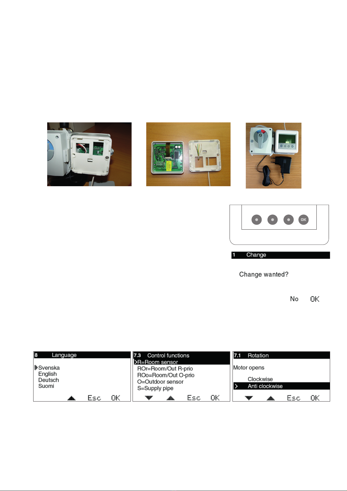
One press on any of the buttons starts the display. The second press on any button
opens the first available menu.
The buttons’ function is then displayed above the respective buttons. Button 1 =
Move down/right or reduce value
Button 2 = Move up/left or increase value
Button 3 = Return/escape
Button 4 = OK/activate menu
None of the values can be changed “by mistake”. In all of the modes
where it is possible to change a value, you will be prompted whether you are sure you
want to make the change before the value is actually changed.
Basic settings on first start-up
At the first start-up, after the first press on OK, you will be guided through the quick start process (see photos below), first
System 1 and then System 2 (if System 2 is connected):
Initiation of wireless room sensor is only shown if the antenna is connected. See separate instruction.
When using two systems, a common menu is shown as first picture. See pages 45-46.
Other basic settings
The maximum limit is set from 0-90 °C. Factory setting is 60 °C.
The setting is made in menu 7.4.
The minimum limit is set from 0-60 °C. Factory setting is 10 °C.
The setting is made in menu 7.4.
For more advanced settings, such as setting of night reduction etc. - see the complete manual.
1324
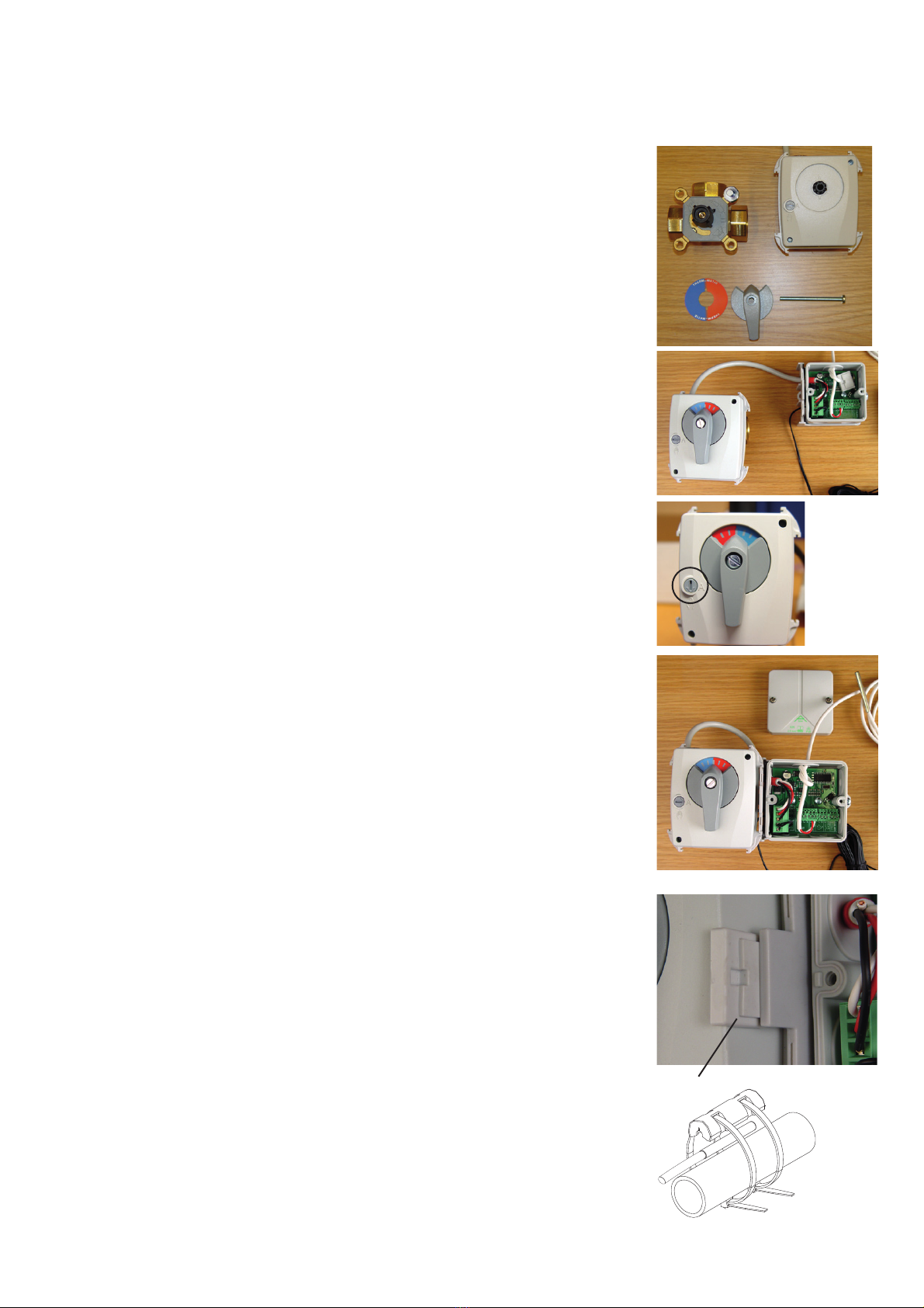
7 Installing the CP or separate room sensor
The CP can be fitted on the CC or on the wall using the enclosed installation kit (plug and screw).
In its standard design, the CP has an integrated temperature sensor that is used as the room sensor. The position of the CP is
therefore decisive for correct operation when using the room sensor function.
The CP should be located centrally in the house, in a hall, stairway or similar space which is linked to as much of the rest of the
house as possible. Avoid rooms with a lot of supplementary heat sources, such as a kitchen, south-facing living room or upstairs
in a two storey house. Position the sensor away from direct sunlight. Avoid placing on an external wall or near an external door.
Make sure the sensor is not positioned closer than 1 m from the nearest radiator and around 1.5 m from the floor.
When using passive room sensor, wireless room sensor, only outdoor sensor or only supply sensor, the
position of the CP is unimportant.
For installation on the CC, see photo 13. The cover screws are then used to fix the CP wall fitting directly to the CC. The multi-
cable is always pulled through the wall fitting as shown in photo 14. Photo 15 shows installation with the CP on the CC.
1413 15

4
110-240 V
9. Start the pump
6. Remove the plastic
strip on one of the
batteries 7. Open the cover and hold the edit
button depressed in order to start the
initiation
8. INI will light for some
seconds – Ready!
Antenna should not be
placed on metallic objects
or on metal pipes.
Antenna should not be
located too close to other
wireless units or power
cables.
Antenna should not be
located too close to
the room unit during
initiation.
Locating the antenna:
Preparation:
THERMOMATIC EC HOME® WL
Quickstart-guide when using wireless room sensor
Other installations and functions are explained in the complete manual for the wireless room sensor
Changing temperature setting
Temperature is easily changed by pressing ”+” or ”-”. Save with ”OK”.
5. Basic settings on first start-up
Menu 7.10 RF Meny
is only shown if the
antenna is connected
110-240 V
2. Fit the motor to
the mixing valve
1. Turn off the pump
4. Plug in the power
supply
3. Fit the flow pipe
sensor
Other manuals for Thermomatic EC Home
2
This manual suits for next models
1
Other Termoventiler Thermostat manuals
Popular Thermostat manuals by other brands

Honeywell
Honeywell TH8320ZW installation guide

White Rodgers
White Rodgers 1F97W-51 Operation guide

BERNSTEIN
BERNSTEIN HT01 Assembly instructions

White Rodgers
White Rodgers 1F82-261 Installation and operation instructions

Heatcom
Heatcom atria Installation and user guide

Solid State Heating
Solid State Heating TSSHC-3DNPSB-16.7A user guide