Terra Electronics sdi410C User manual

1
DVB to IP streamers
sdi410C, sti410C, sda410C, sta410C, sai410C, saa410C
EN RU
Vers. 1.04
This product complies with the relevant clauses of the European Directive 2002/96/EC. The unit must be recycled
or discarded according to applicable local and national regulations.
Equipment intended for indoor usage only.
This product is in accordance to following norms of EU: EMC norm EN50083-2, safety norm EN60065, RoHS norm EN50581.
This product is in accordance with Custom Union Technical Regulations: “Electromagnetic compatibility of technical
equipment“ CU TR 020/2011, “On safety of low-voltage equipment“ CU TR 004/2011.
This product is in accordance with safety standard AS/NZS 60065 and EMC standards of Australia.
1. Product description
DVB-S/S2 (sdi410C, sda410C), DVB-T/T2/C (sti410C, sta410C), DVB-ASI (sai410C, saa410C) to IP streamers (in text
- module) designed to broadcast in multicast on an IP network the services (TV or Radio programmes) issued from FTA or
encrypted digital reception; in case of encrypted signal, a CAM containing the operator's smart card must t the slot. The IP
streams can be viewed using an IPTV set-top box or a software video player. Modules sda410C, sta410C, saa410C have
additional DVB-ASI output with unltered full transport stream.
Modules are intended for indoor use only.
2. Characteristics
Input: one DVB transport stream (MPTS).
Output: up to 24 simultaneous, IP-encapsulated services (TV or Radio programs), with individual multicast addresses
and one MPTS stream.
•BISS descrambling (sda410C, sta410C, saa410C modules).
• Information ltering of DVB tables.
•UDP & RTP transmission protocols.
• Web interface for conguration and setting.
•SNMP agent for monitoring and alarms.
•SAP & SDP protocols that facilitate automatic service selection on the user's STB and provide information to external
servers.
• PID ltering.
•PSI/SI parsing.
•Transparent ECM & EMM messaging.
•PAT, PMT and SDT table regeneration.
•Routing or blocking for CAT, EIT, TDT tables.
• Congurable QoS marking.
• Congurable Time To Live.
3. Safety instructions
Installation of the module must be done according IEC60728-11 and national safety standards.
Any repairs must be made by qualied personnel.
Do not expose this module to moisture or splashing water and make sure no objects lled with liquids, such as vases,
are placed near or on the unit.
Avoid placing the module next to heat sources such as central heating components or in areas of high humidity.
Keep the converter away from naked ames.
If the module has been kept in cold conditions for a long time, bringing it into a warm environment may cause
condensation, so allow it to warm up for no less than 2 hours before plugging into the mains.
Ventilation should not be impeded by covering the module, such as newspapers, table-cloths, curtains etc.
Mount the module in a vertical position only. If installing in a 19” rack system additional forced air cooling fans may be
required (see table "Technical specications" - operating temperature range).
Always allow 10 cm of free space from the top, front and bottom of the unit to enable any heat to be dissipated.
2
5. Installation instructions
Read the safety instruction rst.
All settings can be made using the web browser via control Ethernet interface.
Disconnect power supply unit from the mains before make all connections of modules.
Fasten the module on DIN RAIL or individual holder.
Connect all necessary RF, powering and control cables.
Connect the 75 Ωload to the unused RF output F sockets.
Connect power supply in to mains.
Within 5-20 seconds of powering the module will run in normal operation mode.
Comments of the front panel indicators:
if the link with the control Ethernet interface is established - the LINK [6] indicator glows;
if communication via the control Ethernet interface is active - the ACTIVITY [5] indicator blinks;
if IP streaming is active the - LINK/ACTIVITY [11] indicator blinks at frequency about six times per second, if IP streaming
is inactive - indicator blinks at irregular intervals, if no link of the streaming Ethernet interface - indicator not glows;
if the input signal is present - the status indicator [12] blinks at frequency about three times per second, if no input signal
- indicator blinks at frequency about one time per second.
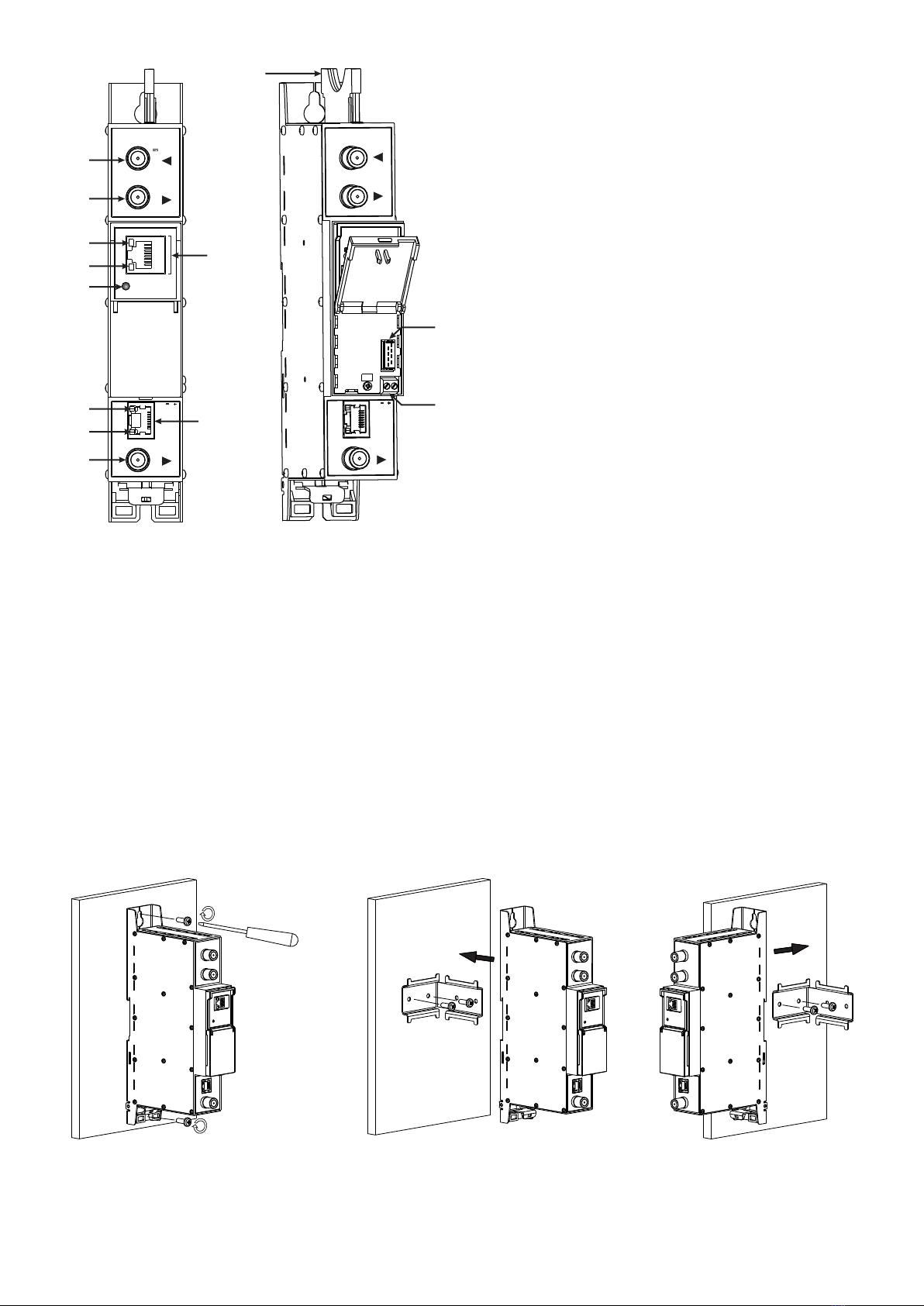
Perpendicular to the wall Parallel to the wall
Figure 2. Mounting of the streamer
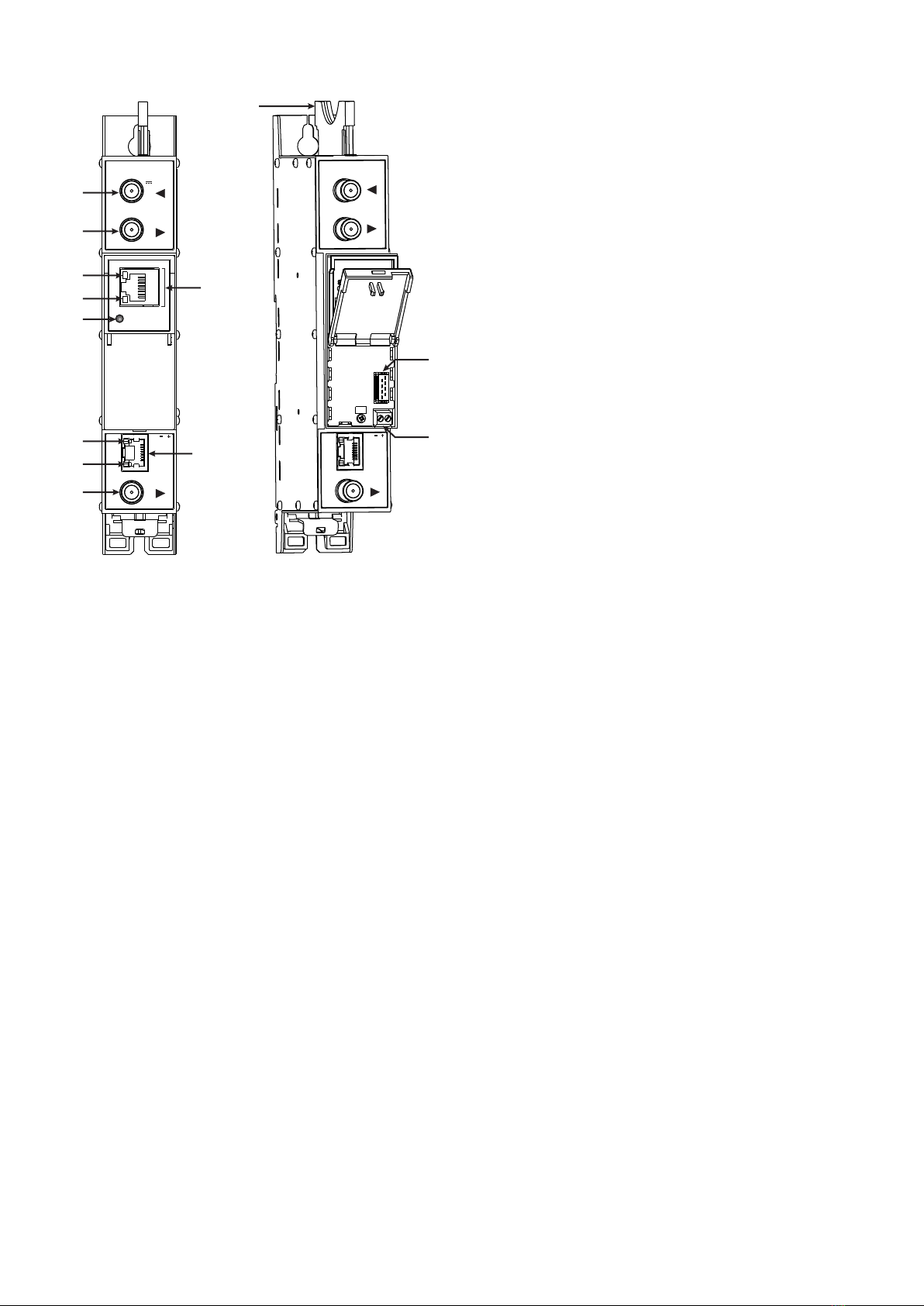
1- CA module slot. PCMCIA socket.
2 - ◄ - RF input of SAT IF signal, DC output for LNB (sdi410C,
sda410C);
RF input of terrestrial TV, cable TV, DC output for preamplier
(sti410C, sta410C);
DVB-ASI input (sai410C, saa410C). F socket.
3 - ►- RF output (input signal loop-through). F socket.
4 - ETHERNET - control Ethernet interface. RJ45 socket.
5 - ACTIVITY (yellow) indicator of the control Ethernet interface.
6 - LINK (green) indicator of the control Ethernet interface.
7- RESET button. Press this button shortly to restart the
module. Press this button for more than three seconds to set
default IP address of the control Ethernet interface.
8- Power distribution bus connector.
9- +12 V powering input (screw terminal).
10 - TS/IP OUT - streaming Ethernet interface. RJ45 socket.
11 - LINK/ACTIVITY (yellow) indicator of the streaming
Ethernet interface.
12 - status indicator (green).
13 - DVB-ASI output (for sda410C, sta410C, saa410C only).
F socket.
Figure 1. External view of the streamer
4. External view
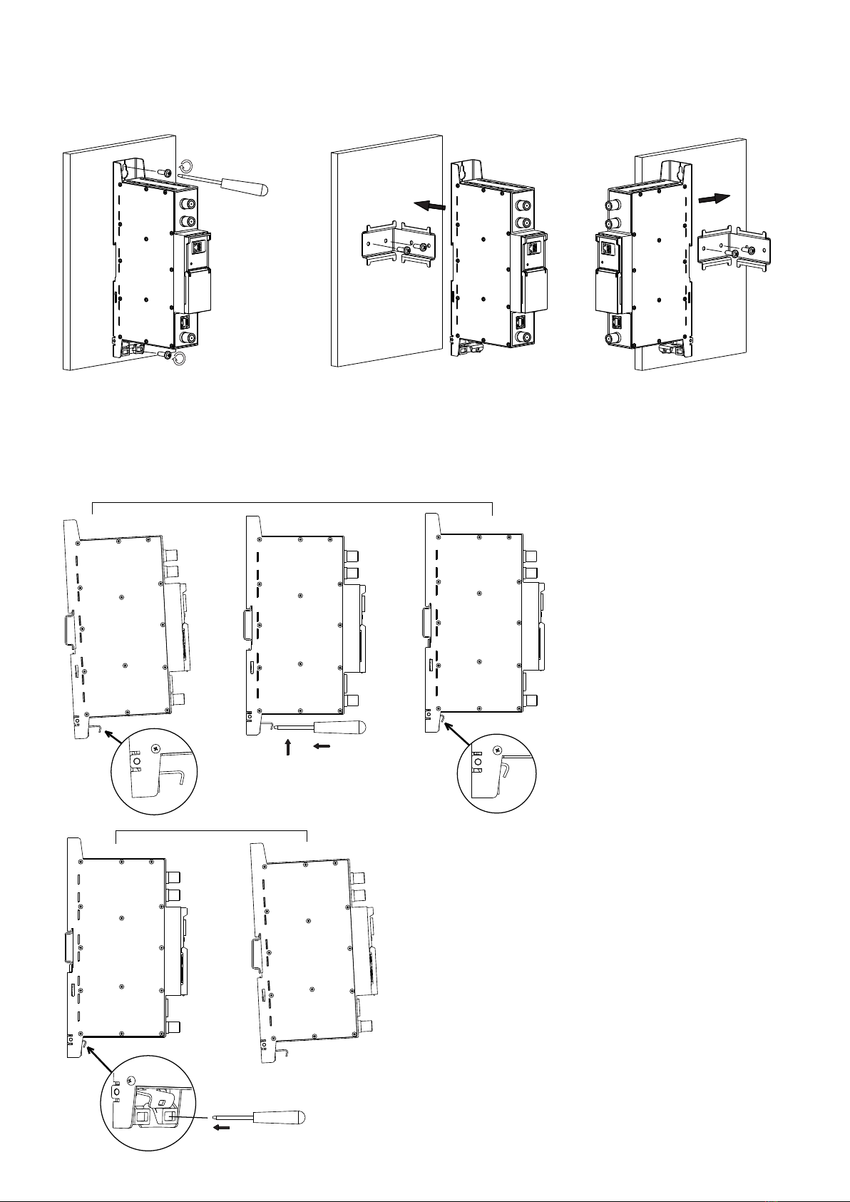
6. MOUNTING
The module or mounting bracket must be xed with steel screws Ø 3.5-4 mm. The screws are not included in a package.
Mounting on a wall by screws Mounting on a bracket (supplied)
DC OUT 12V
0.1A max
sta410C
RESET
ETHERNET
TERRA
DC IN 12V
-
+
TS/IP
OUT
DVB ASI
sta410C
DC OUT 12V
0.1A max
DC IN 12V
-
+
TS/IP
OUT
DVB ASI
2
3
1
4
5
6
7
9
8
10
13
11
12
3
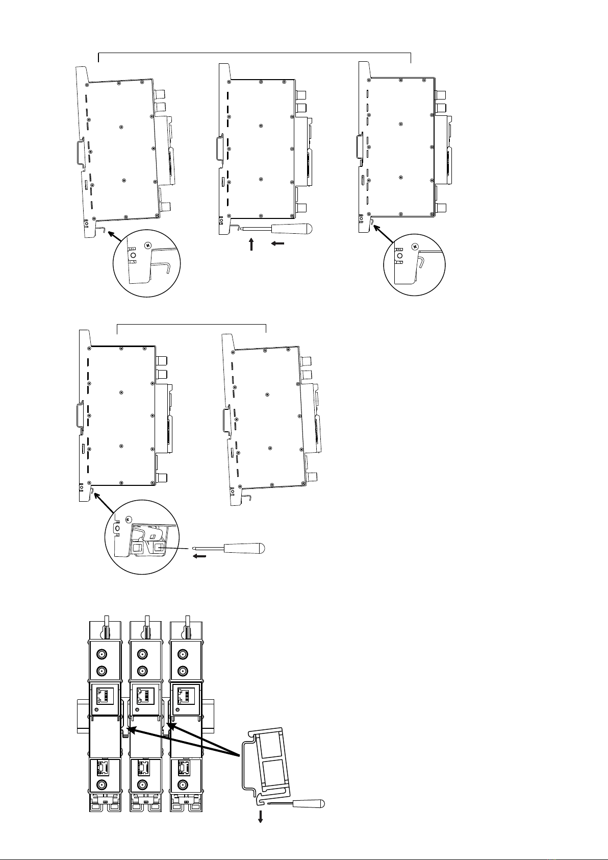
1. 2.
Mounting on DIN rail
Figure 5. Mounting or removing to/from
DIN rail of plastic spacers (supplied).
Figure 3. Mounting to DIN rail
Figure 4. Mounting from DIN rail
4
7. Operating
7.1 Initial conguration
All modules leave the factory with this control Ethernet interface IP address: 192.168.1.10. In order to avoid conicts with
other IP addresses, it is necessary to perform an initial conguration in local mode. Subsequently, it will be possible to access
the modules via the local area network (LAN), either to re-programme it or to check is operating status.
The modules leave the factory with the following Control Ethernet interface TCP/IP conguration:
IP address of the module: 192.168.1.10
Subnet mask: 255.255.255.0
Default Gateway: 192.168.1.1
To access each module, use a PC or MAC personal computer equipped with an Ethernet
card and RJ-45 cable (CAT-5E or CAT-6). The IP address of the PC/MAC must be congured
within the following range: 192.168.1.2 - 192.168.1.254 (do not use 192.168.1.10, since this
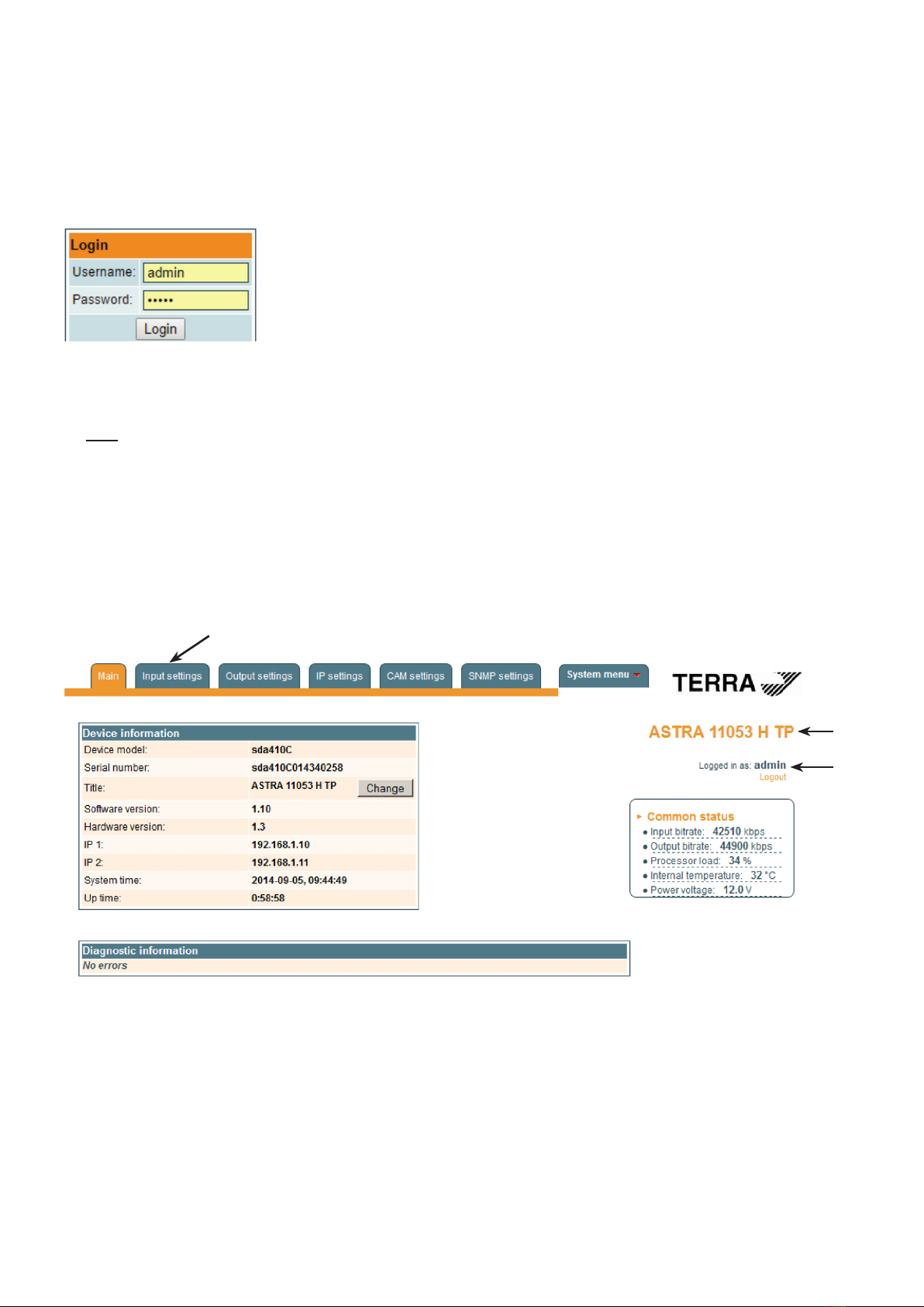
is the IP address of the module to be congured). To start the conguration of the module,
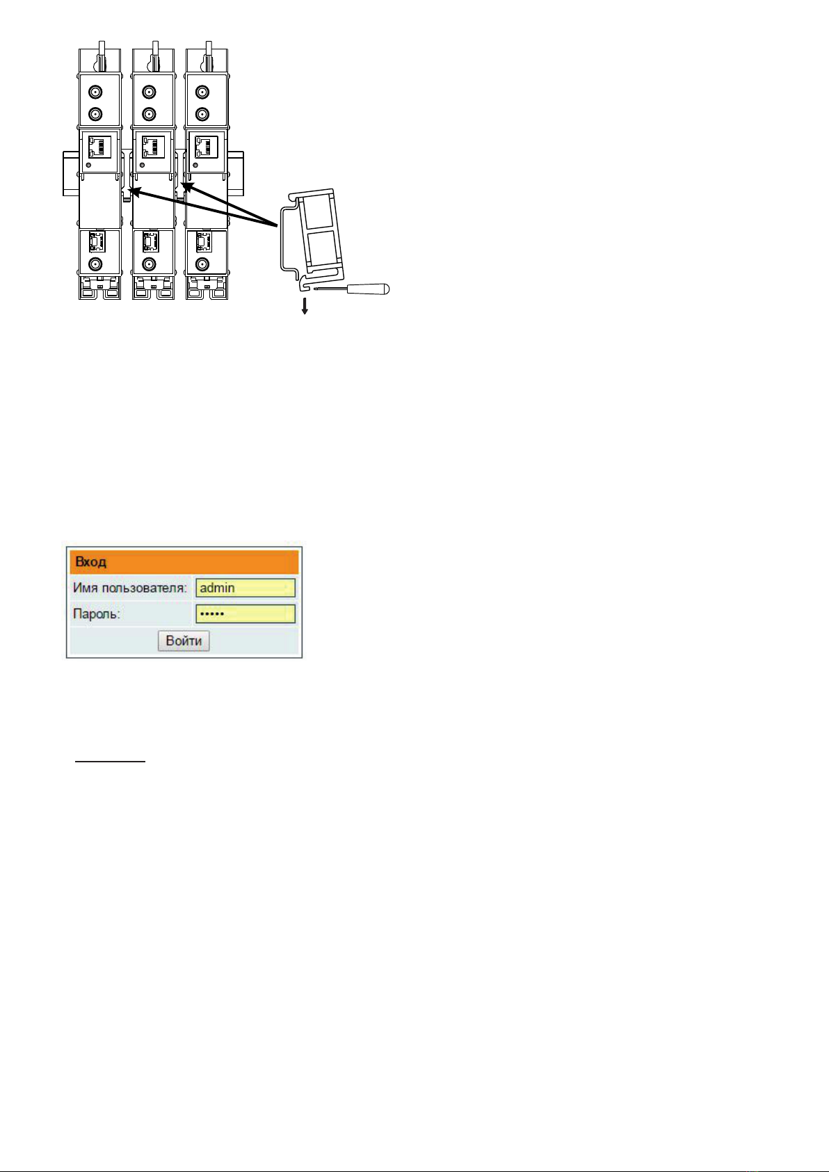
open your web browser and type in the following direction: http://192.168.1.10. The login
prompt will appear on the screen (see Figure 6).
Figure 6. Login prompt
Access to the site is protected by user name and password. The default user name and password is admin. Enter the
user name and password and click on "Login" button.
Note: the default password - admin - can (and must) be changed as explained on section 7.8.5.
During initial conguration you need to change the default control and streaming Ethernet interfaces TCP/IP conguration
as explained on section 7.5.
Control interface IP address reset to default procedure: press the "RESET" [7] button (Figure 1) for more than 3 seconds and
release it. After this operation the control interface IP address will be set to 192.168.1.10, user name and password set to admin.
7.2 General conguration
Initial program screen
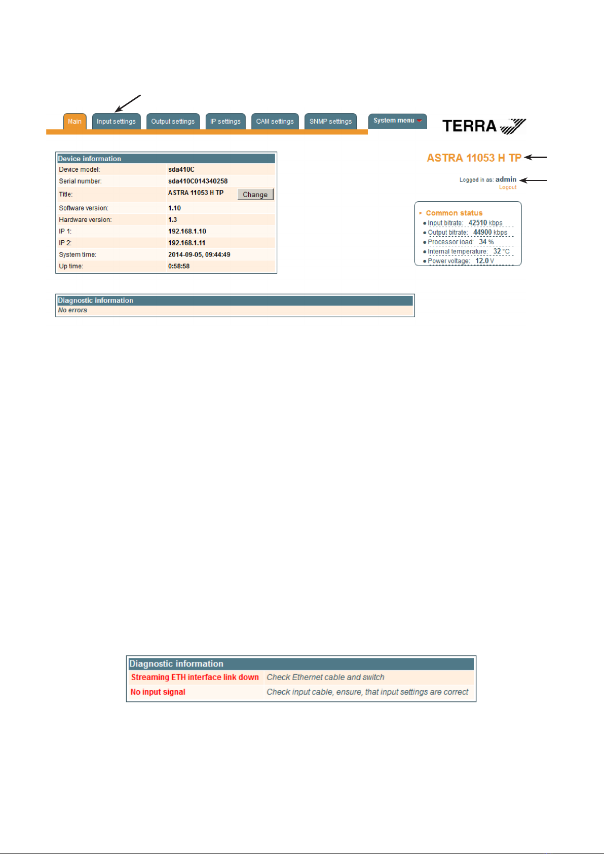
The rst screen that appears when the module accessed contains the "Main" window, which gives general information
on the device.
Figure 7. General information screen
In the top of each conguration screen you will see a main menu tabs [1].
Using it, you can switch between the dierent conguration menus. The tab highlighted in yellow shows which menu is
active at a given moment. The "System menu" tab contains several submenu.
Also common elements for all screens is module title [2] and login information strings [3]. The module title can be changed
after pressing the "Change" button in the "Device information" table. Pressing on the "Logout" string you can logout from
module control.
[1]
[2]
[3]
5
Device information table
This shows the data of module:
"Device model": model of the module.
"Serial number": serial number of the module.
"Software version": module software version number.
"Hardware version": module hardware version number.
"IP 1": IP address of the control interface.
"IP 2": IP address of the streaming interface.
"System time": current time, synchronized from the TDT table of the input stream. Local time oset can be selected in
the "IP settings" tab, see section 7.5.
"Up time": time passed from last power-up or restart of the module.
In the "Common status" table the following parameters are displayed at real time: input bit rate in kbps, output bit rate in
kbps, processor load in percents, internal temperature in degrees of Celsius, power voltage in Volts.
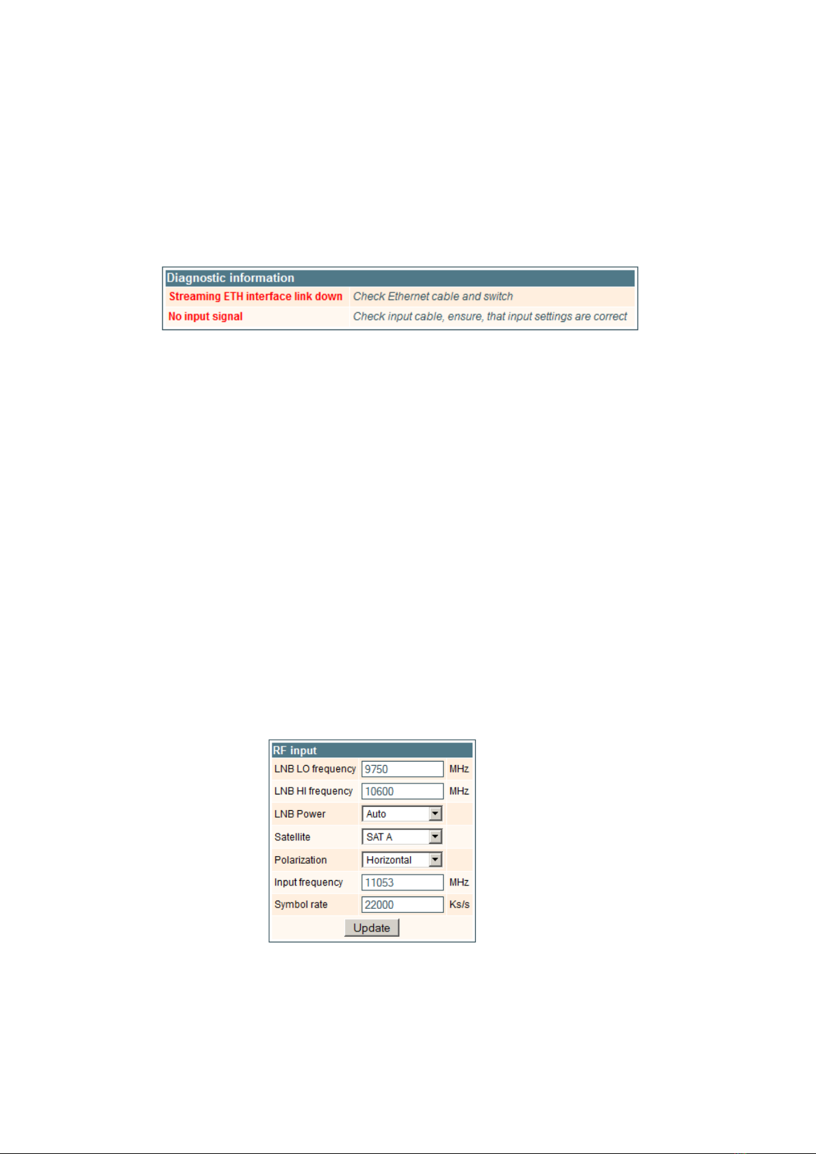
In the "Diagnostic information" table all module errors and comments how to eliminate these errors are displayed.
Figure 8. Diagnostic information table with errors
7.3 Input settings
This screen consists of three tables: "RF input", "List of services" and "Input status". The "RF input" table is used to congure
parameters corresponding to the input satellite transponder (sdi410C, sda410C module), terrestrial or cable transponder
(sti410C, sta410C module), DVB-ASI transponder (sai410C, saa410C module). In the "List of services" table the list of services,
available in the input transponder is displayed. In the "Input status" table you can see real time status of the input section.
The "RF input" table is dierent according the input signal of module.
7.3.1. RF input table
The "RF input" table (Figure 9) for sdi410C, sda410C module consists of following parameters:
"LNB LO frequency" - the LNB local oscillator lower frequency in megahertz. Use 9750 MHz for the universal converter.
"LNB HI frequency" - the LNB local oscillator upper frequency in megahertz. Use 10600 MHz for the universal converter.
“LNB voltage” – power supply of the converter – can be set to “O”, “Auto”, “13V”, “18V”, “13V/22kHz”, “18V/22kHz”. If
“Auto” is selected, power supply voltage of the converter is choosen according to set polarisation – 18V Horizontal, 13V
Vertical; if the “Frequency” of the satellite exceeds the value F=(950+LNB Hi+2150+LNB Lo)/2, the 22 kHz signal is switched
ON and “LNB Hi freq.” is selected.
For example: LNB Hi=10,600, LNB Lo=9750, then F=(950+10,600+2150+9750)/2=11,725 MHz. When power supply of
the converter is set to value dierent from "Auto" - "LNB HI frequency", “Satellite”, "Polarisation" rows are disabled and the
"LNB LO frequency" value is used for IF frequency calculation.
“Satellite” – DISEQC command is used to select the satellite when the switch that supports DISEQC protocol is present.
Possible commands: “None”, “SAT A”, “SAT B”, “SAT C”, “SAT D”.
"Polarisation" - the polarisation of converter. Can be "Horizontal" or "Vertical".
“Frequency” - the frequency of the satellite transponder in megahertz.
“Symbol rate” - the symbol rate of the satellite transponder in kilo symbols per second.
Figure 9. The "RF input" table of the sdi410C, sda410C module
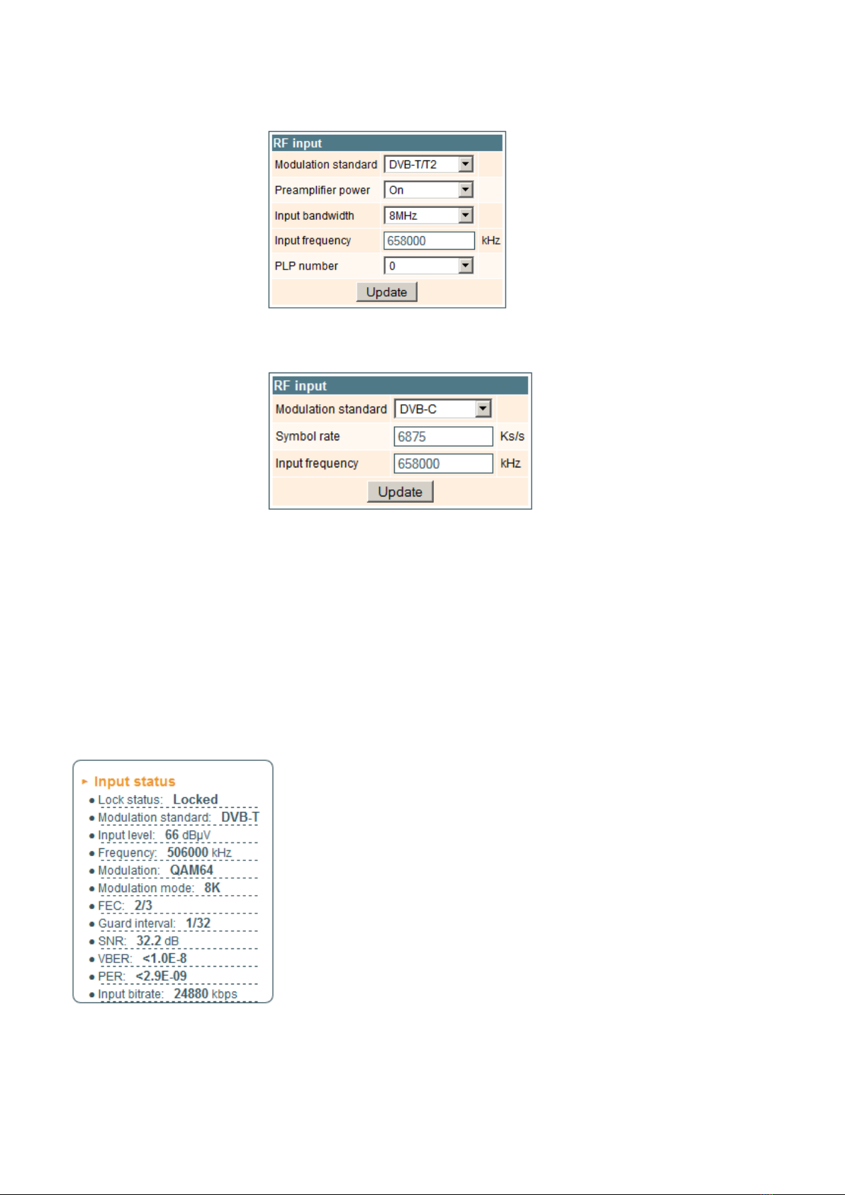
The "RF input" table (Figure 10) for sti410C, sta410C module consists of following parameters:
"Modulation standard" - used to select from the "DVB-T/T2" and "DVB-C" modulation standards.
"Preamplier power" - used to switch on/o the power for the RF preamplier.
"Input bandwidth" - the bandwidth of DVB-T/T2 transponder. Can be selected from values 8 MHz and 7 MHz.
6
"Input frequency" - the frequency of the terrestrial or cable transponder in kilohertz.
When the tuner is locked to the DVB-T2 transponder with multi PLP modulation, the additional parameter "PLP number"
is displayed in the "RF input" table. When the "Modulation standard" set to DVB-C, the "Preamplier power" parameter
is hidden and power for the RF preamplier is switched o; instead of the "Input bandwidth" parameter the "Symbol rate"
parameter is displayed. Enter the value in kilo symbols per second.
Figure 10. The "RF input" table of the sti410C module DVB-T/T2 standard
Figure 11. The "RF input" table of the sti410C module DVB-C standard
Once the dierent data values have been entered, click on Update to conclude the input settings.
7.3.2. Input status table
The following information is displayed in the table “Input status” (Figure 12).
“Lock status” ”Locked” - the streamer module has synchronised with the input signal; "Unlocked” – the streamer module
has not synchronised with the input signal.
“Input level” - RF signal level at the module input. Level indication – approximate.
The values of the following parameters are displayed only if the streamer module has synchronised with the input signal.
“Modulation standard” – detected standard of the input signal. Possible values of the standard: DVB-S, DVB-S2 (sdi410C,
sda410C); DVB-T, DVB-T2, DVB-C (sti410C, sta410C).
“Frequency” – intermediate frequency (sdi410C, sda410C) or RF frequency (sti410C, sta410C) at the module input.
“Modulation” – modulation scheme of the input signal. Possible values of the
modulation scheme: QPSK, 8PSK (sdi410C, sda410C); QPSK, QAM16, QAM32,
QAM64, QAM128, QAM256 (sti410C, sta410C).
“Modulation mode” – OFDM modulation mode of the input signal (sti410C, sta410C
only). Values: 8k or 2k.
“FEC” – forward error correction.
“Guard interval” – guard interval of OFDM signal (sti410C, sta410C only).
“Symbol rate” – the symbol rate of the satellite transponder in kilo symbols per
second (sdi410C, sda410C only).
“SNR” – RF signal/noise ration at the input of module.
“VBER” – bit error rate after Viterbi corrector. To get the signal without any errors
at the output of the tuner, VBER shall not exceed 2Е-4.
“PER” – ratio of the MPEG2 transport error packets to the whole number of packets.
If the number of error packet is equal to zero, the opposite value to whole number of
packets is displayed. Packet counters are reset during RF input parameters update.
“Input bitrate” – bitrate of the input signal.
Figure 12. Input status table

7
7.3.3. List of services table
The table (Figure 13) shows all of the input transport stream services, including dierent details (type, name, identier).
Also UDP unicast streaming via the control interface can be started, services for descrambling by CA module can be selected
and descrambling status observed. Descrambled services available on ASI output of sda410C, sta410C, saa410C modules.
Figure 13. The "List of services" table
The service type icon meanings: SD TV service, HD TV service, radio service.
Click on the "Watch" button to see selected channel. The module will start an UDP unicast streaming via the control
interface. Maximum output bitrate of the UDP unicast is 8 Mbps. VLC Media Player must be installed, downloadable from
http://www.videolan.org
Figure 14. UDP streaming video
The checkboxes in the "Descramble" column are used to select services for descrambling by CA module. Several services
can be selected, if the module supports simultaneous descrambling of several services.
The "Descrambling status" icon meanings: - service is descrambled successfully, - service is not descrambled.
7.3.4. Detailed service information
Press the icon at the start of the list of services line. The detailed service information table will appear:
Figure 15. Detailed service information

8
Figure 17. Streaming settings table
This table is used to see detailed service information and select individual streams for descrambling.
The following service information is shown in the table: service title, service provider, service id, PMT PID, types and
PID-s of service streams, PCR PID. After checking the "Descramble" checkbox of service line, all streams of this service
are included in a descrambling list of the CA module. Unnecessary streams can be deselected from the descrambling list by
unchecking corresponding "Descramble" checkboxes of streams. Close the table by clicking on the icon.
Modules with ASI output (sda410C, sta410C, saa410C) support BISS descrambling function. Descrambled services
available on IP and ASI outputs. BISS code for service scrambled with this scrambling system can be entered in the detailed
service information table (Figure 16).
Figure 16. BISS code table
Enter the BISS code in hex format to "BISS code" box and press the "Update" button.
7.4. Output settings
This screen consists of three tables: "Streaming settings", "SAP/SDP settings" and "Output streams". The "Streaming
settings" table is used specify common streaming parameters to all output streams. The "SAP/SDP settings" table is used to
congure the announcement and service description SAP/SDP channel. The "Output streams" table is used to individually
congure the output streams.
7.4.1. Streaming settings table
This table is used specify common streaming parameters to all output streams.
This table consists of following lines:
"Protocol" - the drop down menu oers two options: UDP and RTP/UDP.
UDP is a transport protocol which is not connection oriented and is particularly
useful for streaming. RTP/UDP adds extra data elds so that the data ow is
served at the correct speed for its projection in real time.
"TS packet count" - count of the MPEG2 TS packets in the UDP packet.
Can be selected from one to seven. It is recommended to select the value
of seven packets.
"Time To Live" - a parameter used to restrict the stream multicasting range. A
number between 1 and 255 is entered in this box. Each time that an IP
stream passes through a router, the TTL is reduced by one unit. The stream
will be rejected by any router when the TTL value is reduced to zero.
"QoS" - quality of Service. The drop down list oers ve dierentiated service options or Diserv. These options relate to the
priority that you wish to assign to the streaming packets on their routes through switches or routers that are QoS management
capable.
QoS values:
1 - Top priority
2 - High priority video
3 - Low priority video
4 - Video and voice
5 - Best eort (best eort made to correctly deliver the video data and the associated audio data)
"Count of output streams" - count of output streams, displayed in the "Output streams" table bellow. Can be selected
from one to twenty ve. After updating ot the FR input parameters this count is automatically set to input stream count value.
"Send IGMP query messages" - enable of the IGMP query messages transmitting. Enable this function when the streaming
output of module is connected to the menageable Ethernet swith with IGMP snooping support. In order for IGMP snooping
to function, a multicast router must exist on the network and generate IGMP queries. The tables created for snooping are
associated with the querier. Without a querier the tables are not created and snooping will not work. When the IGMP query
messages send enabled, the module acts as the multicast router. It is sucient to enable the IGMP query in one module per
one Ethernet switch.
Once the dierent data values have been entered, click on "Update" to conclude the streaming settings.

9
7.4.2. SAP/SDP settings table
This table is used to congure the announcement and service description SAP/SDP channel. SAP and SDP are two
protocols for creating an EPG type program guide.
Figure 18. SAP/SDP settings table
"Enable" - check the box if you wish to transmit the program guide.
"Sending period" - introduce the time interval, in seconds, at which the transmitted programmes guide will refresh.
"Username" - the name entered will be transmitted on the SAP/SDP channel.
"IP address" - multicast address of SAP/SDP messages. It is need to be changed only when your IP receiving equipment
use dierent address.
"Group names" - the names of SAP/SDP groups whose can be assigned to the output streams.
Click on "Update" to save the SAP/SDP channel conguration data.
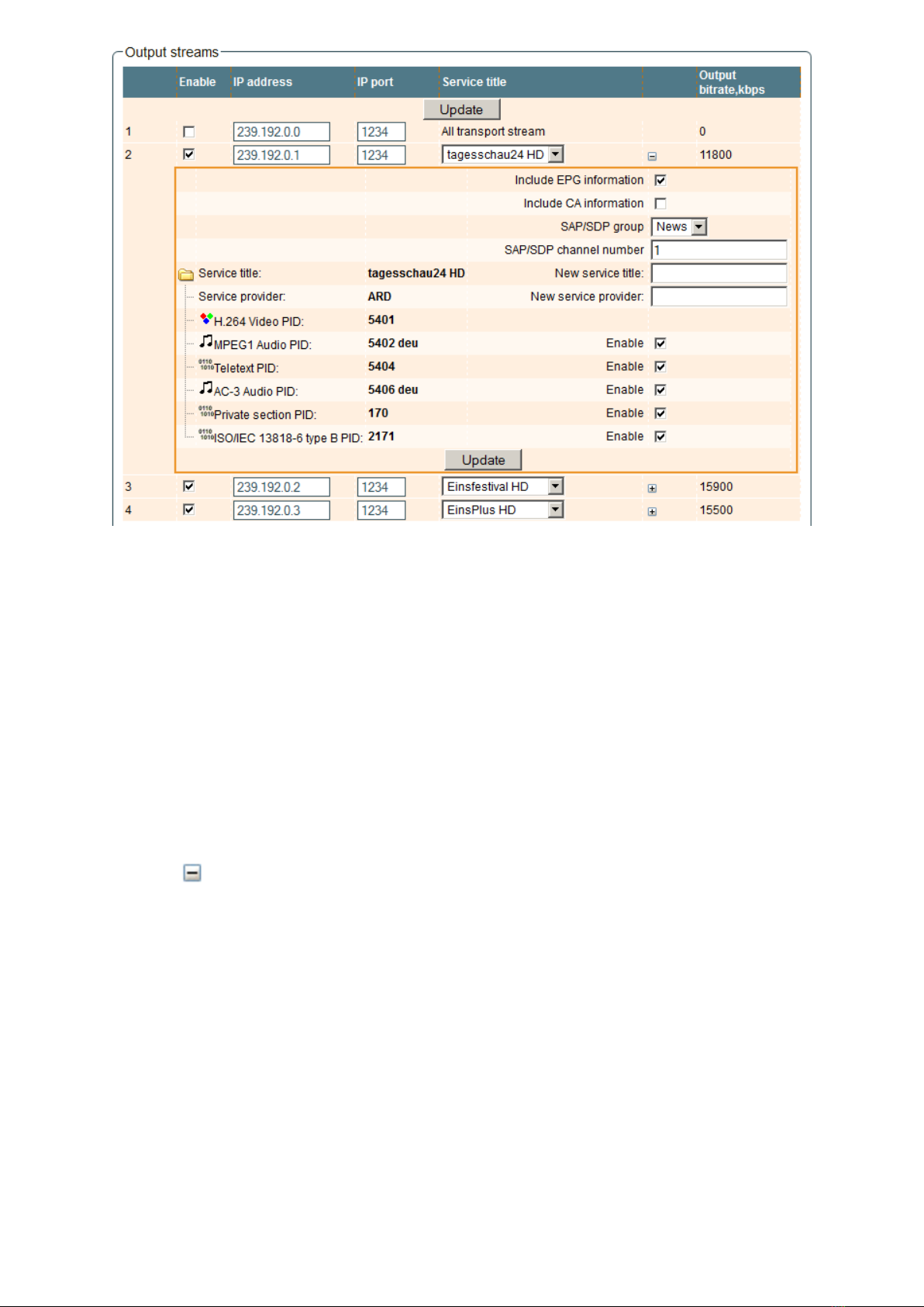
7.4.3. Output streams table
This table is used to individually congure the output streams.
Figure 19. Output streams table
The description of the table columns.
"Enable" - enable streaming of service.
"IP address" - the multicast address required for the stream to be added. The available range is from 224.0.0.0 to
239.255.255.255, but it is recommended to reduce it from 224.0.1.0 to 238.255.255.255.
"IP port" - the IP port required for the stream to be added. The default value is 1234.
"Service title" - select the service from available input services. In the second line sending of the entire transport stream
can be enabled.
"Output bitrate" - current output bitrate of stream in kbps. When the streaming Ethernet interface is not connected, all
output bitrates will be zero.
To conrm the conguration, click on the "Update" button.
7.4.4. Advanced output settings
For advanced users, the possibility exists of opening an additional table with further conguration options related to the
output services. To open this table, click on the icon next to the service title.
10
Figure 20. Extended settings of output streams table
The description of the table rows:
"Include EPG informantion" - check this to include EPG infomation from the input stream.
"Include CA information" - check this to include all conditional access information required to descramble output service
at the IP receiving side. Leave this checkbox unchecked when service is descrambled by the inserted CA module.
"SAP/SDP gruop" - select from the drop down menu the SAP group to which you want to link the service. The group will
have been previously created through the SAP/SDP settings table (see Figure 18).
"SAP/SDP channel number" - enter the order number you want to assign to the service on the subscriber's set-top box
or reproducer, if the device supports SAP.
"New service title" - the name given to the service on the subscriber's set-top box or reproducer, if the device supports
SAP/SDP protocol. The name that the service has on the input transport stream is the default name. Also this name will be
used as the output service name.
"New service provider" - enter the provider name of the output stream. This name will be used in the SDT table.
Within the "Enable" checkboxes next to the stream PIDs is possible to select the streams to be broadcast for eath service
(the video PID cannot be disabled). By default, all the PIDs are selected and remain so until this conguration is altered.
When you have made your selection, conrm it by clicking on the "Update" button and close the advanced settings table
by clicking on the icon.
7.5. IP settings
This screen (Figure 21) consists of four tables: "Control interface IP parameters", "Streaming interface IP parameters",
"Time parameters" and "IP status". The IP parameters tables are used to congure ethernet connection parameters of both
interfaces. In the time parameters table a local time oset can be set. In the IP status table current status of both Ethernet
interfaces and total output bitrate is displayed.

11
Figure 21. IP settings screen
The description of the "IP parameters" tables rows.
"MAC Address" - the physical address of the module's ethernet network card is displayed automatically.
"IP Address" - enter the IP address that you wish to assign to the module. This address must fall within the range of local
network addresses.
"Subnet mask" - enter the local network mask.
"Gateway" - enter the IP address of this gateway. This information is only required if you want to access the module from
the Internet.
It is possible to control the module via streaming interface. Check the enable WEB control from streaming interface
checkbox to enable this function. Note: for security reasons WEB control from streaming interface schould be disabled.
7.6. CAM settings
This screen consists of three tables: "CA module monitor", "CA module information" and "CA module menu". In the "CA
module monitor" table CAM restart function in case of descrambing error can be enabled. It is recommended to turn o this
option if inactivated conditional access card has been inserted.
The content of the remaining tables depends on the inserted CA module.
Figure 22. CAM settings screen
12
In the CA module information table general information about inserted CA module is displayed. When there no CA module
insterted, in the "Status" line is a message: "No module inserted" and remaining lines are empty. Othervise, the "Status"
contains message "Initialised" and remaining lines are lled with information read from the CA module.
As an example, above "CA module menu" table shows the menu for a particular CAM. Click on the corresponding band
to access dierent options. Click on the "Back" button to return to previous menu, click on the "Home" button to return to
start menu.
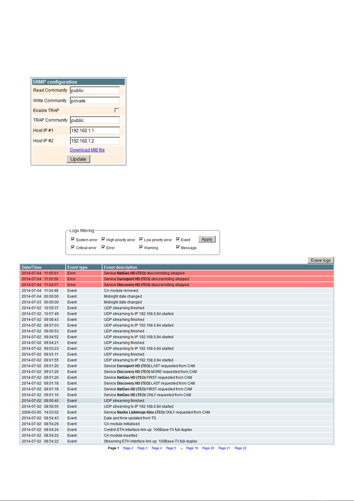
7.7. SNMP settings
This menu tab contains the SNMP conguration table.
The description of the "SNMP conguration" table rows.
"Read Community" - community name acts as a password that is shared
by multiple SNMP agents and one or more SNMP managers. The "Read
Community" password is used for read-only access to streamer parameters.
"Write Community" - is the password used for read-write access to streamer
parameters.
"Enable TRAP" - SNMP traps are alerts generated by agents on a managed
device. Check this box to enable TRAP generation. The streamer generates
traps when the diagnostic message occurs.
"TRAP Community" - is the password used for accessing of TRAPS.
"Host IP #1","Host IP #2" - IP addresses of hosts with SNMP managers,
where TRAPS will be send.
Figure 23. SNMP conguration
7.8. System menu
This menu tab contains following submenu items: "Event logs", "Export parameters", "Import parameters", "Firmware
upgrade", "User management", "Restore defaults", "Reset the device", "Language".
7.8.1. Event logs
Move the mouse on the System menu tab then click on the "Event logs" line. The event logs screen will appear.
Figure 24. Event logs table
13
This enables you to see a list of the log messages of the module. Log contents remains after the power loss of module.
Events in the log e are sorted by time – the newest are in the beginning. Information events are shown in blue background,
error messages are in red. After switching on the unit, the current date is set to 2000:01:01 and time to 00.00.00. When the
MPEG stream is received, the information about date and is decoded too, and the values of these parameter are corrected.
Local time oset in the log is used from the time parameters table (see Figure 21). You can lter required messages setting
corresponding "Logs ltering" checkboxes.
7.8.2. Export parameters
All of the data established on the streamer module can be saved onto a backup le. Inversely, the conguration data
saved on an appropriate le can be restored on streamer module. Move the mouse on the System menu tab then click on the
"Export parameters" line. A window is displayed which allows you to select the action for the data le for the current streamer
conguration. You need to select the "save le to disk" option.
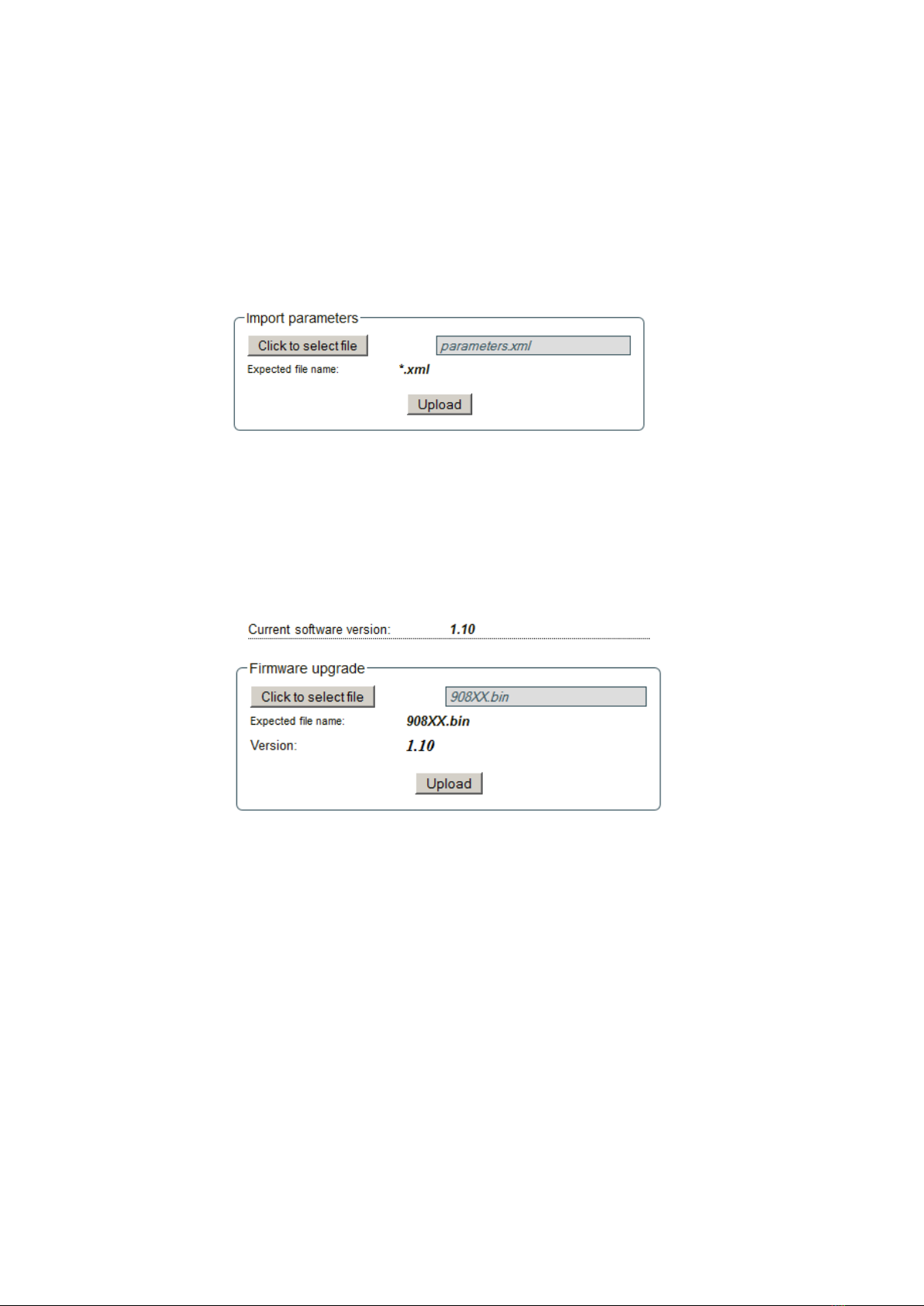
7.8.3. Import parameters
Select this option in "System menu" tab. The Import parameters window is displayed.
Figure 25. Import parameters window
Click on "Click to select le" and select the le containing the conguration data that you wish to restore on the streamer
module. Once you have selected the le, click on the "Upload" button at the bottom of the screen. The upload conrmation
window will be displayed.
7.8.4. Firmware upgrade
If you wish to update the streamer's rmware, select this option in "System menu". The card displayed shows the rmware
version that the streamer has at the present time.
Figure 26. Firmware upgrade window
Click on "Click to select le" and select the rmware update le from the hard drive. When the le name is in the box, click
on "Upload". The new rmware will be installed on the streamer.
14
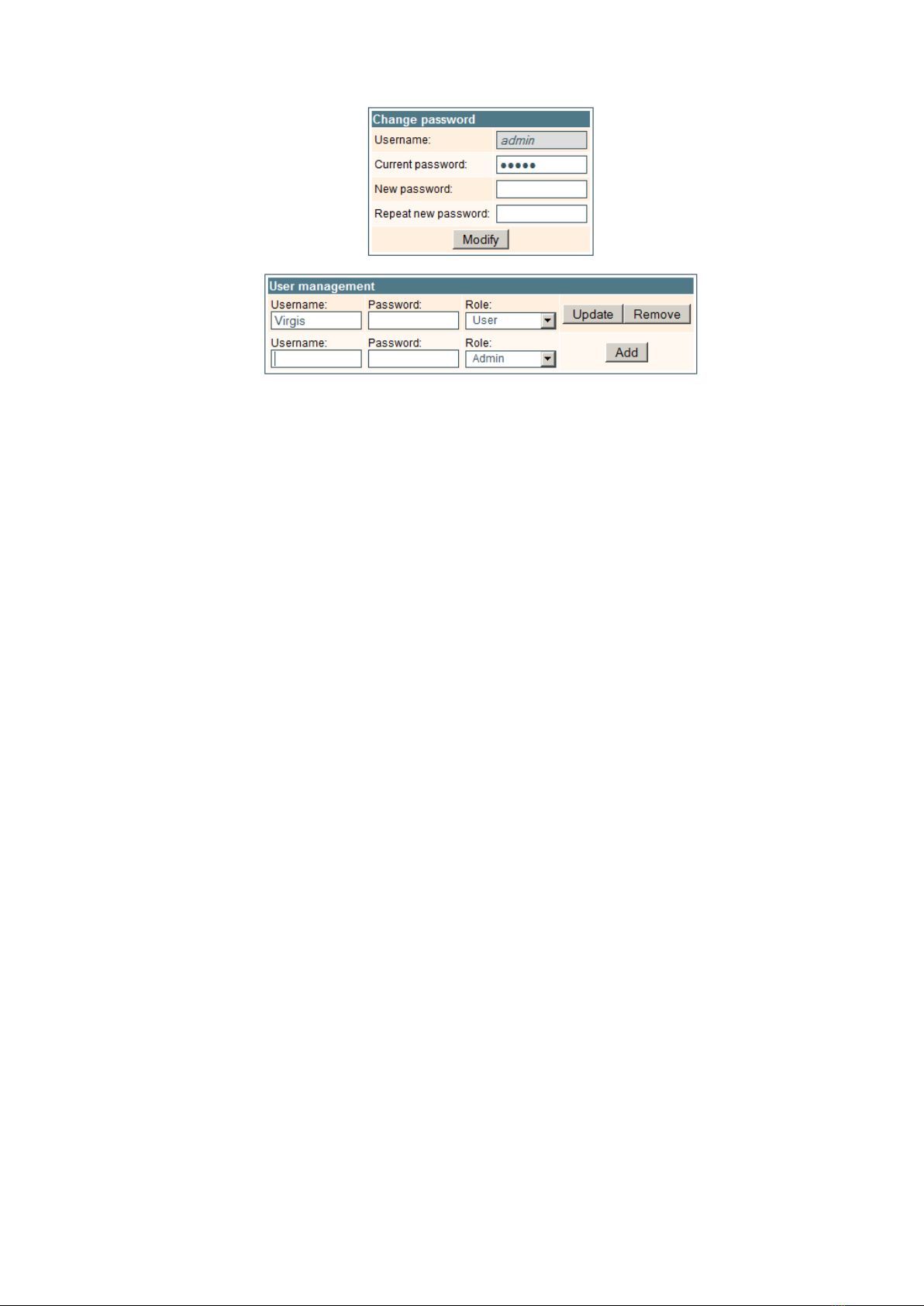
7.8.5. User management
Select this option in "System menu" tab. The user management window is displayed.
Figure 27. User management window
This window consits of two tables: "Change password" and "User mamagement". The "Change password" table allows
you to change the password. Enter the new password in the "New password" eld and conrm the new password retyping it
in the "Repeat new assword" eld. The change of password will not take eect until you press the "Modify" button.
In the "User mamagement" table you can manage users, who will be able to login into the streamer. Enter the new username
and password in the appropriate elds, select desired role for user and press the "Add" button to add new user or "Update"
button to change settings of the user. User role "Admin" enables the password change function and user management function.
User role "User" enables only password change function. Press the "Remove" button to remove user from list.
7.8.6. Restore defaults
Clicking on the "Restore defaults" submenu in the "System menu" tab resets the conguration of the streamer module to
the factory default values. The Control and streaming interfaces IP parameters remains unchanged.
7.8.7. Reset the device
Clicking on the "Reset the device" submenu in the "System menu" tab causes the streamer module to restart.
7.8.8. Language
If you wish to change the streamer's menu language, select this option in the "System menu".

15
Draugystes str. 22, LT-51256 Kaunas, Lithuania, tel.: +370 37
-
31 34 44, fax: +370 37
-
31 35 55
* without external DC feeding and CAM; with CAM ≈0.3 A
Type sdi410C sti410C sai410C sda410C sta410C saa410C
RF input QPSK / 8PSK COFDM / QAM -QPSK / 8PSK DVB-C COFDM / QAM
frequency range 950-2150 MHz 47-862 MHz - 950-2150 MHz 47-862 MHz -
AGC range/impedance 45-85 dBµV/75 Ω 30-80 dBµV/75 Ω - 45-85 dBµV/75 Ω 30-80 dBµV/75 Ω -
symbol rate 2 ÷45 Ms/s - - 2 ÷45 Ms/s - -
ASI input packet length -- 188 / 204 bytes - - 188 / 204 bytes
bit rate - - up to 72 Mbps - - up to 72 Mbps
input voltage - - 200...880 mVpp - - 200...880 mVpp
impedance - - 75 Ω- - 75 Ω
return loss - - >15 dB - - >15 dB
LNB powering/control 0/14/18 V & 0/14/18 V &
300 mA max. - - 300 mA max. - -
DiSEqC 1.0 DiSEqC 1.0
DC output for preamplifier, max. - 12 V 100 mA - - 12 V 100 mA -
IP output standard IEE802.3 10/100 Base T
bit rate up to 100 Mbps
number of simultaneous up to 24
streams
transmission protocols UDP/RTP
multicast, MPTS, SPTS Yes
ASI bit rate - up to 72 Mbps
output impedance - 75 Ω
packet length - 188 bytes
MPTS - only
Management port standard IEE802.3 10/100 Base T
Supply voltage 12 V ± 1 V
Current consumption** 0.2 A
Operating temperature range 0o ÷ +50o C
Dimensions/Weight (packed) 36x198x107.5 mm/0.84 kg
Technical specications

1
DVB в IP стримеры
sdi410C, sti410C, sda410C, sta410C, sai410C, saa410C
RU
Vers. 1.04
Данный продукт соответствует требованиям Европейской Директивы 2002/96/EC. Устройство должно
быть переработано или утилизировано в соответствии с местными и региональными правилами.
Оборудование предназначено работать в закрытых помещениях.
Данный продукт соответствует следующим нормам Европейского Союза: электромагнитной совместимости EN50083-2,
безопасности EN60065 и RoHS EN50581.
Данный продукт соответствует требованиям технических регламентов Таможенного Союза: “Электромагнитная
совместимость технических средств“ ТР ТС 020/2011, “О безопасности низковольтного оборудования“ ТР ТС 004/2011.
Данный продукт соответствует нормам безопасности по стандарту AS/NZS 60065 и нормам электромагнитной совместимости по
стандартам Австралии.
1. Описание изделия
IP-стримеры с поддержкой стандарта DVB-S/S2 (модели sdi410C и sda410C), стандарта DVB-T/T2/C (модели
sti410C и sta410C) и стандарта DVB-ASI (модели sai410C и saa410C) (в дальнейшем – «модули») предназначены
для многоадресного потокового транслирования в IP-сети сервисов (видео- и аудиопрограмм), принимаемых в
открытом или зашифрованном цифровом формате. Для декодирования закрытого контента предусмотрен съемный
модуль (САМ-модуль), содержащий смарт-карту оператора. Просмотр IP-потоков возможен с использованием IPTV-
телевизионной приставки либо программного видеоплеера. В модулях sda410C, sta410C и saa410C предусмотрен
дополнительный DVB-ASI выход с нефильтрованным полным транспортным потоком.
Модули предназначенны работать в закрытом помещении.
2. Характеристики
Вход: один DVB транспортный поток MPTS.
Выход: до 24 одновременных IP-инкапсулированных теле- и радиопрограмм программ с собственными групповыми
адресами и одним потоком MPTS.
• дескремблирование потоков, зашифрованных в кодировке BISS (модели sda410C, sta410C и saa410C);
• фильтрация информации в таблицах DVB;
• поддержка протоколов управления передачи данных UDP и RTP;
• веб-интерфейс для режимов конфигурирования и настройки;
• SNMP-агент для наблюдения и сигнализации о необычном событии;
• поддержка протоколов SAP и SDP, облегчающих автоматический выбор программ в телевизионной приставке
абонента и поставляющих внешним серверам информацию о программе;
• фильтрация PID;
• анализ PSI/SI-информации;
• прозрачный проход сообщений ECM и EMM;
• регенерирование таблиц PAT, PMT и SDT;
• проход или блокировка таблиц CAT, EIT и TDT;
• конфигурируемые уровни качества обслуживания (QoS);
• конфигурируемое время жизни пересылаемого пакета (TTL).
3. Инструкция по электробезопасности
Инсталляция стримера должна быть проведена в соответствии с требованиями IEC60728-11 и национальных
стандартов безопасности.
Ремонтировать стример может только квалифицированный персонал.
Не устанавливайте стример в местах, где есть возможность попадания брызг или капель воды.
Не ставьте сосудов (напр. ваз) с водой или другими жидкостями вблизи стримера, чтобы избежать попадания
жидкостей внутрь стримера.
Не устанавливайте стример вблизи приборов отопления, а также в помещениях повышенной влажности.
Держите конвертер вдали от открытого огня.
После длительного хранения стримера при низкой температуре, необходимо перед включением выдержать его в
теплом помещении не менее двух часов.
Не закрывайте стример посторонними предметами, напр. газетами, шторами;
При инсталляции крепите стример в вертикальном положении. При инсталляции модуля в 19'' коммутационную
стойку, может понадобится дополнительный вентиляторный блок для охлаждения модулей (см. таблицу ''Технические
характеристики'' - Диапазон рабочих температур.)
Сверху, cпереди и cнизу установленного стримера должно быть не менее 10 см свободного пространства.
2
5. Порядок установки модуля и выполнения подключений
Прочитайте указания по соблюдению мер безопасности при выполнении работ по подключению устройства.
Все настройки могут быть выполнены через управляющий интерфейс Ethernet с использованием веб-браузера.
До начала работ по подключению модуля отключите блок питания от питающей сети.
Установите и закрепите модуль на планке "DIN rail" или в отдельной стойке.
Подключите все радиочастотные, питающие и управляющие кабели.
Подключите нагрузку сопротивлением 75 Ом к неиспользуемым гнездам типа F радиочастотного выхода.
Подключите модуль к питающей сети.
Через 5-20 секунд после подключения модуль должен начать работать в нормальном эксплуатационном режиме.
Показания светодиодных индикаторов:
При установлении соединения с управляющим интерфейсом Ethernet загорается индикатор соединения [6].
При активном состоянии связи через управляющий интерфейс Ethernet индикатор активности [5] горит мерцающим
светом (мигает);
При активном состоянии режима потоковой передачи IP-данных индикатор активности/соединения [11] горит
мерцающим светом (мигает) с интервалом примерно шесть раз в секунду, при неактивном состоянии режима индикатор
мигает с произвольной периодичностью. При нарушении или отсутствии соединения с потоковым интерфейсом
Ethernet индикатор гаснет.
При наличии входного сигнала индикатор состояния [12] горит мерцающим светом (мигает) с интервалом примерно
три раза в секунду, при отсутствии входного сигнала индикатор мигает с периодичностью примерно один раз в секунду.
1 - PCMCIA гнездо для установки модуля условного доступа.
2 - ◄ - РЧ вход для приема ПЧ СТВ сигналов; DC выход для
питания LNB (sdi410C, sda410C);
РЧ вход наземного ТВ, кабельного ТВ, DC выход для
предусилителя (sti410C, sta410C);
вход DVB-ASI (sai410C, saa410C). Гнездо типа F.
3 - ►- РЧ выход (для проходного суммирования по РЧ).
Гнездо типа F.
4 - ETHERNET - разъем RJ45 управляющего интерфейса
Ethernet.
5 - Светодиодный индикатор активности (желтый) управляющего
интерфейса Ethernet.
6 - Светодиодный индикатор соединения (зеленый)
управляющего интерфейса Ethernet.
7 - Кнопка RESET (Сброс). При однократном коротком
нажатии кнопки выполняется перезарузка модуля. При
однократном нажатии и удержании кнопки более трех
секунд выполняется установка стандартного IP-адреса
управляющего интерфейса Ethernet.
8 - Разъем шины питания.
9 - Напряжения питания +12 V (винтовой разъем).
10 - TS/IP OUT - разъем RJ45 потокового интерфейса Ethernet.
11 - Светодиодный индикатор активности/соединения
(желтый) потокового интерфейса Ethernet.
12 - Светодиодный индикатор состояния (зеленый).
13 - DVB-ASI выход (только для sda410C, sta410C, saa410C).
Гнездо типа F.
4. Внешний вид
DC OUT 12V
0.1A max
sta410C
RESET
ETHERNET
TERRA
DC IN 12V
-
+
TS/IP
OUT
DVB ASI
sta410C
DC OUT 12V
0.1A max
DC IN 12V
-
+
TS/IP
OUT
DVB ASI
2
3
1
4
5
6
7
9
8
10
13
11
12
Рис. 1. Внешний вид стримера
3
Перпендикулярно к стене Параллельно к стене
Рис. 2. Крепление усилителя
6. Крепление
Прикрепите модуль или угольник к стене стальными болтами или саморезами диаметром 3.5-4 мм. Крепежные
элементы не входят в комплект поставки.
Крепление к стене саморезами Крепление на угольнике (входит в комплект поставки)
1. 2.
Крепление к планке''DIN rail''
Рис. 3. Крепление к планке ''DIN rail''
Рис. 4. Демонтаж с планки ''DIN rail''
4
Рис. 5. Крепление или демонтаж к/либо
с ''DIN rail'' пластиковых вставок
(входят в комплект поставки).
7. Порядок работы с модулем
7.1 Начальная конфигурация
На всех модулях установлен следующий стандартный IP-адрес управляющего интерфейса Ethernet: 192.168.1.10.
В целях избегания конфликта с другими IP-адресами необходимо выполнить начальную конфигурацию в
локальном режиме. В дальнейшем будет обеспечена возможность доступа к модулям по локальной сети для их
перепрограммирования или проверки рабочего состояния.
Стандартная конфигурация протоколов TCP/IP управляющего интерфейса Ethernet:
IP-адрес модуля (IP address of the module): 192.168.1.10
Маска подсети (Subnet mask): 255.255.255.0
Шлюз по умолчанию (Default Gateway): 192.168.1.1
Для доступа к каждому модулю используйте любой персональный
компьютер или персональный компьютер семейства Apple Macintosh,
оснащенный Ethernet-адаптером и кабелем RJ-45 категории CAT-5E или
CAT-6. IP-адрес компьютера должен быть назначен в следующем диапазоне:
192.168.1.2 - 192.168.1.254 (не использовать значение 192.168.1.10, так как
оно является IP-адресом конфигурируемого модуля). Для начала процесса
конфигурации модуля откройте веб-браузер и наберите в адресной строке
следующий IP-адрес: http://192.168.1.10. На экране появится окошко с
запросом входа в систему (см. рис. 6.).
Доступ к сайту защищен паролем и именем пользователя. Имя пользователя и пароль по умолчанию: admin.
Введите их в соответствующие поля и нажмите на кнопку "Войти".
Внимание!: Пароль - admin - по умолчанию может и должен быть сменен в порядке, изложенном в пункте 7.8.5.
В ходе начальной конфигурации необходимо изменить стандартные настройки протоколов TCP/IP управляющего
и потокового интерфейсов Ethernet в порядке, изложенном в пункте 7.5.
Порядок сброса IP-адреса управляющего интерфейса на адрес по умолчанию: нажмите и удерживайте в течение
не менее трех секунд кнопку RESET (Сброс) [7], а затем отпустите ее. При этом будет выполнена установка IP-адреса
управляющего интерфейса на значение 192.168.1.10, а имени пользователя и пароля – на admin.
Рис. 6. Окошко с запросом
входа в систему
5
7.2 Общая конфигурация
Начальный экран программы
Первый экран, который появляется после входа в систему, содержит главное окно программы с общей информацией
об устройстве.
Рис. 7. Экран с общей информацией об устройстве
В верхней части каждого экрана конфигурации находятся вкладки [1] главного меню, с помощью которых можно
переключаться между различными меню конфигурации устройства. Меню, которое активно в данный момент, выделено
на экране желтым цветом. Вкладка "System menu" (Системное меню) содержит несколько вложенных подменю.
Общим элементом всех экранов является наличие строки с названием модуля [2] и строк c данными входа в
систему [3]. Название модуля может быть изменено путем нажатия кнопки "Change" (Изменить) в таблице "Device
information" (Сведения об устройстве). При нажатии на строку "Logout" (Выход) выполняется выход пользователя из
системы управления модулем.
Таблица Device information (Сведения об устройстве)
В таблице указываются следующие сведения о модуле:
"Device model" (Модель устройства). Модель модуля.
"Serial number" (Серийный номер). Серийный номер модуля.
"Software version" (Версия программного обеспечения). Номер версии программного обеспечения модуля.
"Hardware version" (Версия аппаратного обеспечения). Номер версии аппаратного обеспечения модуля.
"IP 1". IP-адрес управляющего интерфейса.
"IP 2". IP-адрес потокового интерфейса.
"System time" (Системное время). Текущее время, синхронизированное по таблице TDT входного потока. Величину
сдвига местного времени можно задать во вкладке IP settings (Настройка параметров интернет-протокола IP) (см.
пункт 7.5).
"Up time" (Время доступности). Время, прошедшее с момента последнего включения питания или перезагрузки
модуля.
В таблице "Common status" (Общее состояние) в режиме реального времени отображаются следующие параметры:
скорость входного потока в кбит/сек, скорость выходного потока в кбит/сек, нагрузка на процессор в процентах от
полной, внутренняя температура в 0C и напряжение питания в вольтах.
В таблице "Diagnostic information" (Диагностическая информация) показываются все ошибки при работе модулей
и рекомендации по их устранению.
Рис. 8. Таблица Diagnostic information (Диагностическая информация),
отображающая ошибки, возникшие при работе модуля
[1]
[2]
[3]
This manual suits for next models
5
Table of contents
Languages:


