TerraMarNetworks trac6140 User manual

I-021 - trac6140/1/2 - Installation Guide Ver. 2.1
tracpoint | Support Team
1 | P a g e
Installation Guide
This is a bespoke installation guide for the TerraMar Networks | trac6140/ 6141/ 6142 tracking device (referred to as the “Device” in this document.) If in any doubt,
please consult the tracpoint support team, using the contact details shown at the end of this document.
trac6140 –Includes standard wiring loom 12V/24V compatibility
trac6141 –Includes ACCY1056 Complete Accessory wiring loom 12V only (voltage label will be included on loom)
trac6142 –Includes ACCY1075 Complete Accessory wiring loom 24V only (voltage label will be included on loom)
1. BOX CONTENTS
Please ensure all the following parts are present before beginning the installation of the Device:
STANDARD PARTS –See Figure 1
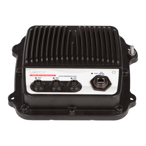
trac6140 Device
Basic Loom (attached)
Phantom ignition sensor
GPS antenna
Fuse holders x3
Fuses x3 (1amp –2amp –5amp)
Tamper stickers x5
Cleaning pad
EXTRA PARTS AVAILABLE BY REQUEST/ORDER
Driver ID (ACCY1073) –see Figure 2
Panic Button (ACCY1012/ACCY 1013) –see Figure 2
Immobilisation circuit (ACCY1010) –see Figure 2
Complete Accessory loom 12V(ACCY1056) –see Figure 3 –includes phantom ignition sensor (PIS)
Complete Accessory loom 24V (ACCY1075) –see Figure 3
Fig 1: Standard Parts

I-021 - trac6140/1/2 - Installation Guide Ver. 2.1
tracpoint | Support Team
2 | P a g e
Fig 2: Application Options
Fig 3: Optional Looms

I-021 - trac6140/1/2 - Installation Guide Ver. 2.1
tracpoint | Support Team
3 | P a g e
2. PREPARE DEVICE
Remove 6 Philips head screws from back of trac6140
Fig 4
Insert SIM card, if not already inserted in SIM card holder
Securely fix 6 Phillips head screws to Device
Prepare loom and identify the cables that are needed for your specific installation configuration
Apply one tamper sticker over the opening of the Device. Position the sticker such that, if the Device is subsequently opened, the tamper sticker will be torn.
3. MOUNT DEVICE IN VEHICLE
Find a secure location under the dash of the vehicle to mount the Device. Remove all panels necessary to give a good view of the area to be worked on. The
Device can be mounted using the self-adhesive pad on the back of the Device OR cable ties, securely fastened OR a combination of cable ties and the self-
adhesive pad. Position the Device carefully –see Fig. 4 Device Positioning in this document. Device positioning is important: incorrect orientation of the Device
can result in false readings from the on-board 3-Axis accelerometer.
Mounting GPS antenna –see Section 4
DO NOT FIT DEVICE IN ENGINE COMPARTMENT
NEVER OBSTRUCT AIRBAGS, OR OTHER SAFETY FEATURES IN THE VEHICLE, WITH THE DEVICE OR ANY OF ITS ASSOCIATED WIRING
NEVER OBSTRUCT THE NORMAL OPERATION OF THE VEHICLE BY BLOCKING THE DRIVER’S VIEW
NEVER BLOCK THE DRIVER’S NORMAL OPERATION OF, AND ACCESS TO, INSTRUMENTS
ENSURE DEVICE IS NOT INSTALLED ON ANY SURFACE THAT MAY BE SUBJECTED TO LARGE FLUCTUATIONS IN TEMPERATURE
When deciding on the routing of cables, follow the proposed route of cables first, to ensure all lengths of cabling are adequate, e.g., power, earth, ignition feed,
etc. Ensure that the location of the Device allows adequate distance to the source of the feeds.

I-021 - trac6140/1/2 - Installation Guide Ver. 2.1
tracpoint | Support Team
4 | P a g e
Fig 4: Device Positioning
Fig 5: Wiring Diagram (See Fig 14 for ACCY1056 & ACCY1075 wiring diagram)
4. INSTALL ANTENNAE
GPS
GPS antenna is external. Follow these instructions for the correct installation of GPS antenna for optimum performance
Ensure surfaces are clean before fixing antenna.
GPS antenna can and should be installed UNDER the dash of the vehicle where possible. It may be obstructed by plastic trim but not obstructed by any
metallic objects. There is a self-adhesive label on the back of the GPS antenna for fixing. Self-adhesive label should face down and the other side of the
antenna should face the sky.
GSM
GSM antenna is inside the device enclosure, therefore care must be taken when positioning the Device
General Notes
The performance of the equipment may be impeded if the GPS antenna or Device are mounted beneath, or in very close proximity to, electrically conductive
materials, such as metal, metalized film or laminate windscreens. If this applies to the vehicle in which you work, please install the antenna and Device
elsewhere. A 20cm (7.87 inch) separation distance between the Device and all persons must be maintained at all times. The Device should not be fitted in
close proximity to any AM /FM radio or any other RF instruments installed in the vehicle.

I-021 - trac6140/1/2 - Installation Guide Ver. 2.1
tracpoint | Support Team
5 | P a g e
5. POWER
TAKE CARE WHEN WIRING INTO ANY VEHICLE. CARRY OUT PRE-INSTLLATION CHECKS TO ENSURE THERE ARE NO PRE-EXISTING FAULTS ON
THE VEHICLE’S DISPLAY. IF YOU FIND A FAULT, DISCUSS WITH THE CLIENT OR tracpoint Support BEFORE CONTINUING.
A source of power should be identified using a multi-meter. Main feeds going to the fuse board are the preferable option. Connect to a permanent positive
supply (10-32V) via a 2 Amp in-line fuse. Cover fuse-holders with tamper proof sticker provided.
Fig 6: Power Connection
It is strongly recommended that power pick up points are chosen that DO NOT form part of an auxiliary supply, such as a cigar lighter or auxiliary power
socket, as these can be compromised by the connection of third party Devices, such as power chargers, inverters, tools etc.
All connections should be soldered, unless using a suitable eyelet terminal on a threaded bolt secured with matching nut on the vehicle.
WHEN SOLDERING, CARE MUST BE TAKEN NOT TO DAMAGE SURROUNDING WIRING WITH HEAT FROM IRON’S EXHAUST.
SOLDER IN WELL-VENTILATED AREAS. SOLDER FUMES MAY BE HARMFUL
6. EARTH
When choosing an earth point, it is advisable to take an earth from a predefined chassis point. There should be no electrical resistance present between the
Device and earth.
Fig 7: Earth Connection
7. IGNITION
Ignition feed must be sourced from a point which only comes ‘live’ when the engine is switched on. Fuse with 1 Amp fuse, covered with tamper proof sticker.
To get a true engine running feed, an ignition feed must be sourced that only becomes live when the engine is switched on and is lost when the engine is
switched off again. Alternatively, use Phantom Ignition Sensor supplied. See comments below with reference to the PIS and Fig. 9
IF USING COMPLETE ACCESSORY LOOM (ACCY1056), THE PHANTOM SENSOR (PIS (12V only)) IS ALREADY PRESENT ON THE LOOM. PLEASE
REFER TO SECTION 16, Fig 14 FOR MORE INFORMATION. IGNITION WIRE ON ACCY1056 IS BLUE IN COLOUR
Fig 8: Ignition Feed Connection
In-line Phantom Ignition Sensor (12V ONLY)
The Phantom Ignition Sensor (PIS) is used to simulate an engine running feed when a true engine running feed is not available.
The PIS (12V) is supplied with the trac6140 as a standard component. If using the trac6140 on a 24V installation, do not use the PIS supplied.
In the case of the trac6141, the PIS (12V) is integrated into the ACCY1056 Complete Accessory Loom.
The PIS is not available as part of the trac6142 or its ACCY1075 Complete Accessory Loom.
Note: The term “engine running feed”means there is a voltage (feed) present only when the engine is actually running.
The PIS is a box which connects to the main power line for the Device. Once the engine is switched on in a vehicle, the current and voltage in the vehicle will
rise, as the alternator engages to charge the battery in normal operating mode. This box will sense the difference in voltage and throw an input high on engine
start, simulating that of a true engine running feed.

I-021 - trac6140/1/2 - Installation Guide Ver. 2.1
tracpoint | Support Team
6 | P a g e
Fig 9: PIS Connections 12V only
Wiring Instructions
Wiring is as follows:
oRED soldered to +12V source –2 Amp Fused
oBLACK soldered to –ve source
oBLUE soldered to Ignition wire on the Device
Commissioning Test
Note that there is an LED on the Phantom Ignition Sensor (PIS)
When engine is not running, LED will flash intermittently
After engine has been started, the LED will be lit continuously and there will be a 12V feed available on the BLUE wire
KNOWN PROBLEM
The LED remains illuminated permanently after the ignition is switched off in the vehicle
SOLUTION
Change the red wire to a switched ignition feed
Conduct the Commissioning Test again
IF THIS DOES NOT CORRECT THE PROBLEM, CONTACT tracpoint Support BEFORE CONTINUING.
8. DALLAS I-BUTTON / DRIVER ID
Driver ID receiver should be mounted on the dash of the vehicle, within easy reach of the driver, without obstructing any of the vehicle’s instruments. Drill a
suitably sized hole for the DriverID receiver. Insert and secure receiver using the fastener to the rear. Wiring of the Driver ID is as follows:
Fig 10: Driver ID Connections
9. INPUTS
All of the digital inputs on the Device (including ignition) have the same specification and are capable of detecting a signal up to 32V. Inputs are deemed to have
gone HIGH when the input voltage rises above 6V and LOW when the voltage is less than 6V at 1A current draw.
10. PANIC ALARM
Select a location for the Panic button in a discreet area on the vehicle’s dashboard. Drill a suitably sized hole and mount the button.
Fig 11: Panic Button Connections
11. PTO (INPUT)
One of the most commonly monitored inputs on a truck / HGV is the power take-off (PTO) feed. PTO draws power from a vehicle’s driveshaft to power an accessory,
such as a secondary pump, crane, lifting axles, fuel pump, etc.
This switch is
normally open
N/O

I-021 - trac6140/1/2 - Installation Guide Ver. 2.1
tracpoint | Support Team
7 | P a g e
Install
an electrical PTO by taking a feed off the switched live feed on the PTO line - see Fig 12
a pneumatic PTO by taking a feed from the pneumatic switches- see Fig 12.1
Fig 12: PTO Connection
Fig 12.1 Pneumatic PTO
12. FINAL CHECKS
Once the installation has been completed, take some time to go back through the installation step-by-step.
Here are some of the items that need to be checked!!
Device secure
Device not obstructing the driver or any moveable parts
Wiring safely routed
Connections soldered, fused and insulated
Correctly rated fuses inserted
Tamper stickers applied to:
oFuses
oDevice enclosure
GPS antenna secure and unobstructed
All cable ties left safe and evenly cut
All panels securely fitted
All controls in the vehicle have been tested
13. DASH CHECK
Check for warning lights on dash display
14. Device LED CHECKS
There are a series of LED’s on the device shown in Fig. 13 below. These LED’s are used as an indicator to the installer that certain aspects of the device installation
are working as expected.
GPS
This accessory ACCY1001
is available if needed

I-021 - trac6140/1/2 - Installation Guide Ver. 2.1
tracpoint | Support Team
8 | P a g e
GSM
1-Wire DALLAS iButton / DRIVERID
Fig 13 Device LED Sequences
15. COMMISSIONING
Contact tracpoint Support to have the Device commissioned.
Please have the following information available:
Vehicle registration
Customer name
Job#
IMEI
Job type
Vehicle make
Vehicle model
Ignition type
VIN #
SIM#
Odometer reading
Please record all information listed above, then send it to tracpoint Support via email. Contact details are on page 10 of this document

I-021 - trac6140/1/2 - Installation Guide Ver. 2.1
tracpoint | Support Team
9 | P a g e
16. COMPLETE ACCESSORY LOOM (ACCY1056 –12V variant / ACCY1075 –24V variant)
ACCY1056 includes a 12V phantom ignition sensor
ACCY1075 does not include phantom ignition sensor –care must be taken to choose an actual engine running feed on 24V vehicles to ensure that the
igntion feed reads voltage from the vehicle only when the engine is running
***CARE MUST BE TAKEN INSURING CORRECT VOLTAGE RATING LOOM IS USED***
The Complete Accessory Loom incorporates all the extra features and options of the trac6140. It is designed to simplifiy the initial installation and facilitate the
addition of other features in the field later.
WIRING COLURS IN THE FOLLOWING DIAGRAMS MAY DIFFER FROM WIRING PREVIOUSLY SHOWN IN THIS DOCUMENT. WIRING IN THIS
SECTION SHOULD ONLY BE USED IF USING THE ACCY1056 COMPLETE ACCESSORY LOOM
ACCY1056 includes the following components:
Fuseholders for V+ & Ignition feeds
Phantom ignition (PIS) for 12V Vehicles Only*
Immobilisation relay 12V
All additonal wiring –panic, driverID, Immobilisation, phantom ignition (PIS), power and earth points
ACCY1075 includes the following components:
Fuseholders for V+ & Ignition feeds
Immobilisation relay 24V
All additonal wiring –panic, driverID, Immobilisation, power and earth points
Fig 14: Complete Accessory Loom Connections

I-021 - trac6140/1/2 - Installation Guide Ver. 2.1
tracpoint | Support Team
10 | P a g e
This manual suits for next models
2
Table of contents
