Terwin 2000 Series User manual

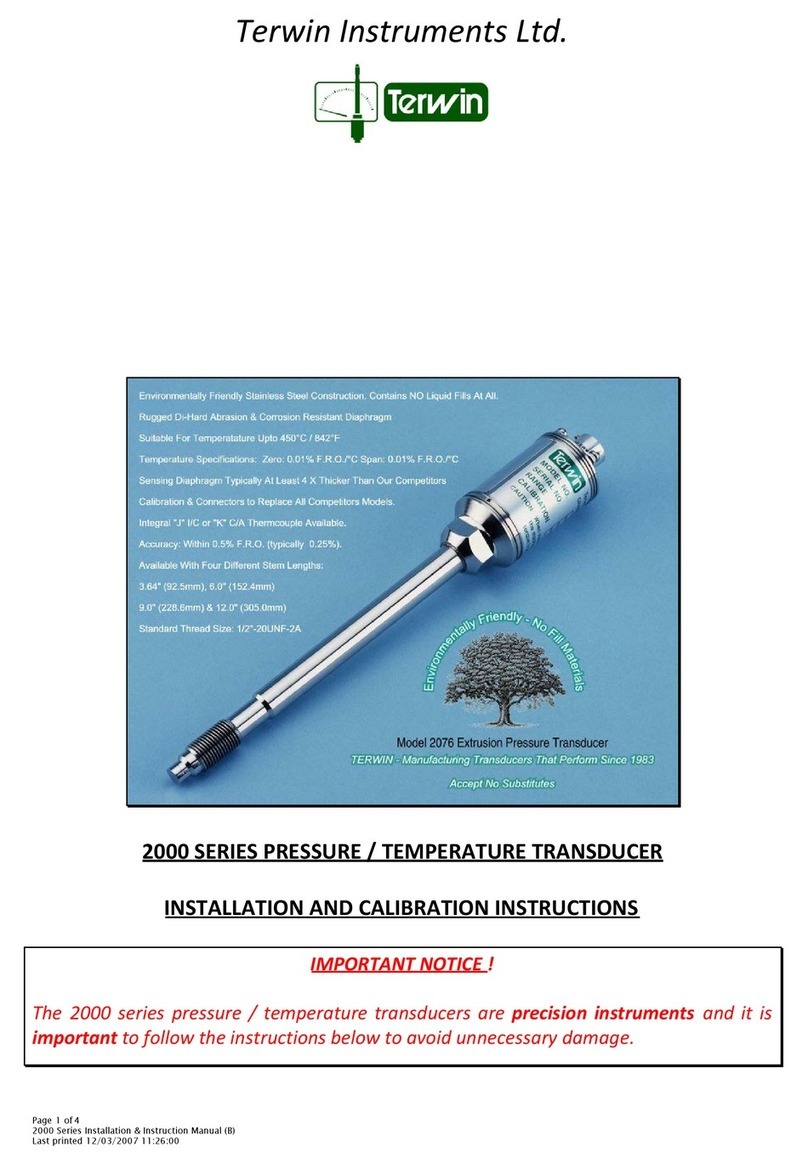
Terwin 2000 series Extrusion Pressure Transducers
Handling procedures to give maximum life.
All melt transducers, regardless of who manufactures them, should be handled with great care and it is
important that they are installed into the extruder adhering to the manufacturer’s installation procedures
(see enclosure giving Terwin recommendations).
During the manufacture and shipping of our transducers, every precaution is taken to ensure that our
products reach you in perfect condition. Each transducer is manufactured to our customer specifications
with the appropriate pressure range, effective stem length, thread size, electrical connector, thermocouple
output and any other options that may be called for.
Prior to final calibration, each transducer is cycled extensively on a pressure/temperature test rig at 20%
over the normal range of the transducer i.e., a 0 – 10,000 psi transducer will be cycled at 12,000 psi at a
temperature of 200°C / 392°F. This procedure is carried out to ensure that transducer is both mechanically
and thermally stable when put into service.
Further more, during final calibration, each transducer is subject to an overload pressure of up to twice the
full range pressure or 22,500 psi, which ever is less. This is to ensure that the transducer can withstand the
normal running or occasional peak pressures without damage to the diaphragm or strain gage assembly
that is built into the electrical termination head. Even after this overload, it should be noted that the
diaphragm, which is in contact with the polymer remains flat.
During final inspection, the transducer is fitted with a plastic thread/diaphragm protection cap and a square
rubber gasket that is fitted over the electrical termination head. This last item prevents the transducer
rolling off a work station prior to installation, which if allowed to happen, could result in severe mechanical
shock and damage to the strain gage assembly.
Additionally, each transducer has attached to it a Cautionary Installation Label giving recommended
procedures. This is further supported with the provision of an Installation/Calibration Instruction Manual
plus a Final Assembly Test Data Sheet.
Figure 1 on the following page illustrates all items provided at time of dispatch.
T:\Terwin Templates\Manuals\2000 Series Manual\Transducer Handling Procedures (c).doc
Page 1 of 4

Figure 1
The protective cap and gasket should be left on the transducer until such time that the mounting port on
the extruder has been prepared for use using a Transducer Mounting Hole Cleaning Tool Kit. Installation of
transducers into ports that are contaminated with old material is one of the primary causes of failure as
hardened plastics can tear the diaphragm and this means that the transducer is rendered useless.
The cleaning kit will help ensure that the 45°sealing face is clean, the hole allowing the tip of the
transducer to pass freely into the extruder is clear and the threads are free from debris. Please refer to the
attachment to this article, which illustrates a cleaning kit.
Each kit contains a ½-20UNF-2A four-fluted bottoming tap, cleaning drill with guide and handle, gage
blanking plug, allen wrench and one pot of Dykem Blue.
The suggested procedures for using these kits are as follows:
1. Clean the port threads using the four-fluted bottoming tap until the threads are clean.
2. With the cleaning drill inserted into the guide sleeve and handle attached, screw the guide sleeve
into the extruder mounting port – finger tight only. Now in a clockwise direction, push and turn the
cleaning drill so that any old material is removed from the 45°sealing face and transducer tip
mounting hole. The procedure may have to be carried out several times until the tool is clean when
finally removed.
T:\Terwin Templates\Manuals\2000 Series Manual\Transducer Handling Procedures (c).doc
Page 2 of 4

3. Apply a coating of Dykem Blue on the gauge blanking plug over the whole area below the threads.
Screw the plug into the extruder until it bottoms out on the 45°face. Remove the plug and inspect
– only the 45°face should have had any blueing removed. If there is evidence that blueing has been
removed from other surfaces, this may mean that the port has not been cleaned correctly or the
port has not been machined properly.
4. Having ensured that the port is now fit for purpose, remove the plastic protective cap from the
transducer threads and screw this into the extruder port. If the threads on the port are clean, it
should be possible to screw the transducer in by hand until it bottoms out on the 45°face. Now
using a torque wrench with a 7/8” crow foot, torque the transducer into the extruder to 20ft.lbs
maximum.
Note: Exceeding the recommended mounting torque could result in damage to the body of the transducer
and internal tubes, thus rendering the transducer useless.
5. Next, remove the protective rubber gasket from the electrical termination head, connect the
appropriate cable assembly to the transducer and the installation is now complete. Now, the
transducer must be calibrated through the measuring instrument as follows:
6. Without running the extruder screw, apply temperature to the extruder until the desired settings
are achieved. Upon reaching temperature, allow 20 minutes for the temperature to stabilize
around the transducer and then adjust the zero on your pressure indicator/signal conditioner and
then check and adjust the calibration at 80% of the full range i.e., on a transducer with a range of
1,500 psi the cal figure will be 1,200 psi. If there are large adjustments to be made, it may be
necessary to repeat the calibration procedure once more. Calibration is now complete and the
extruder may now be started following your standard operating procedures.
Note: Under no circumstances, must the extruder be run until all zones have reached the desired polymer
extrusion temperature, as another primary cause of transducer failure is cold starts. Not only will a cold
start damage the transducer but this can also result in severe damage to the extruder.
EXTRUDER START UP AND SHUT DOWN
On many extruders, manual controls are provided for starting/stopping the extruder drive by means of
delivering an analog signal to the drive circuitry. It has been found that if the extruder drive is subject to a
fast start or closure by cranking up the control potentiometer, this will in effect produce a very fast
pressure peak that is almost impossible to detect, unless the melt pressure transducer is connected to an
instrument such as a UV recorder. However, this fast rising pressure peak is sufficient to destroy the
pressure transducer strain gage assembly and it is therefore recommended that fast starts are avoided.
T:\Terwin Templates\Manuals\2000 Series Manual\Transducer Handling Procedures (c).doc
Page 3 of 4

REMOVAL OF TRANSDUCERS FROM EXTRUDERS
Under no circumstances must transducers be removed from extruders whilst the machine is running or if
there is pressure in the barrel, as this may lead to personal injury. However, it is important that no attempt
should be made to remove a transducer from the extruder whilst polymer in the machine is cold, as it is
likely that the plastic material will have adhered to the diaphragm during cooling and this will lead to the
diaphragm being damaged. Ideally, the transducer should be removed from the extruder when the polymer
is close to the recommended extrusion temperature.
As procedures and materials used in the cleaning of extruders can damage the transducer diaphragm, it is
important that transducers are removed from the machine before cleaning the extruder barrel.
CLEANING OF TRANSDUCERS
Do not use wire brushes or knives to clean solidified polymers from the transducer tip, as irreparable
damage may be inflicted to the diaphragm. To prevent this from happening, heat the probe to the melt
temperature (do not exceed 450
°
C / 842°F) and remove the polymer with a soft clean cloth. Any residue of
material left in the threads can be removed by simply cleaning with a ½-20UNF-2B die and then finally, use
an aerosol mechanical cleaner to ensure that all debris is washed away.
TRANSDUCER CALIBRATION.
Upon initial installation, transducers should be calibrated through the pressure indicator/signal conditioner
as detailed in page 3 paragraph 6. This procedure should also be carried out in the event of a change in the
process temperature, or if the transducer is removed and reinstalled into the extruder, as the zero output
of a transducer will change when it is torqued into the machine.
In the event of calibration difficulties, which may be caused by damage to the transducer, cable assembly
or process indicator, it is recommended that the cable assembly and indicator be checked with a transducer
simulator (see enclosed data sheet), in order that the fault can be isolated to the relative component. This
device allows you to connect your process indicator via your normal cable assembly to the simulator and
perform basic functional checks. Whilst the simulator has reasonably good accuracy, it should be noted that
it is not a calibration standard.
T:\Terwin Templates\Manuals\2000 Series Manual\Transducer Handling Procedures (c).doc
Page 4 of 4
Table of contents
Other Terwin Transducer manuals
Popular Transducer manuals by other brands

TR-Electronic
TR-Electronic LMRI-46 1150 SSI manual
Simrad
Simrad 38-200 COMBI C - REV D datasheet
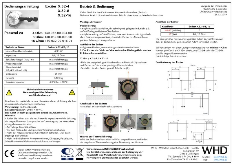
WHD
WHD Exciter X.32-4 quick start guide
S+S Regeltechnik
S+S Regeltechnik Thermasgard RTM Operating Instructions, Mounting & Installation
B-K Medical
B-K Medical 8824 user guide
Tecsis
Tecsis P3230 instruction manual
