Spectris HBM U2B User manual

Force Transducers
U2B
Mounting instructions
B 20.U2B.20 en
SUNSTAR传感与控制 http://www.sensor-ic.com/ TEL:0755-83376549 FAX:0755-83376182 E-MAIL:[email protected]
SUNSTAR自动化 http://www.sensor-ic.com/ TEL: 0755-83376489 FAX:0755-83376182 E-MAIL:[email protected]

SUNSTAR传感与控制 http://www.sensor-ic.com/ TEL:0755-83376549 FAX:0755-83376182 E-MAIL:[email protected]
SUNSTAR自动化 http://www.sensor-ic.com/ TEL: 0755-83376489 FAX:0755-83376182 E-MAIL:[email protected]

3
U2B
HBM 24.5.2000
Contents page
Safety instructions 4. . . . . . . . . . . . . . . . . . . . . . . . . . . . . . . . . . . . . . . . . . . . . .
1 Instructionsfor use 6. . . . . . . . . . . . . . . . . . . . . . . . . . . . . . . . . . . . . . . . .
2 Structure and operating mode 6. . . . . . . . . . . . . . . . . . . . . . . . . . . . . . . .
2.1 Measuring device 6. . . . . . . . . . . . . . . . . . . . . . . . . . . . . . . . . . . . . . . .
2.2 Housing 7. . . . . . . . . . . . . . . . . . . . . . . . . . . . . . . . . . . . . . . . . . . . . . . . .
2.3 Measurementprocess, output signal 7. . . . . . . . . . . . . . . . . . . . . . . .
2.4 Compensatingfor disturbance variables 8. . . . . . . . . . . . . . . . . . . . .
3 Operation on site 8. . . . . . . . . . . . . . . . . . . . . . . . . . . . . . . . . . . . . . . . . . . .
3.1 Ambient temperature 8. . . . . . . . . . . . . . . . . . . . . . . . . . . . . . . . . . . . .
3.2 Humidity 8. . . . . . . . . . . . . . . . . . . . . . . . . . . . . . . . . . . . . . . . . . . . . . . .
3.3 Ambient pressure 9. . . . . . . . . . . . . . . . . . . . . . . . . . . . . . . . . . . . . . . .
3.4 Chemical influences 9. . . . . . . . . . . . . . . . . . . . . . . . . . . . . . . . . . . . . .
3.5 Contamination 9. . . . . . . . . . . . . . . . . . . . . . . . . . . . . . . . . . . . . . . . . . .
4 Mechanicalinstallation 10. . . . . . . . . . . . . . . . . . . . . . . . . . . . . . . . . . . . . .
4.1 Important precautions during installation 10. . . . . . . . . . . . . . . . . . . . .
4.2 General installation guidelines 10. . . . . . . . . . . . . . . . . . . . . . . . . . . . .
4.3 U2B installation for tensile loading 11. . . . . . . . . . . . . . . . . . . . . . . . . .
4.4 U2B installation for tensile and compressive loading 12. . . . . . . . . .
5 Electrical connection 13. . . . . . . . . . . . . . . . . . . . . . . . . . . . . . . . . . . . . . . .
5.1 Notes on cabling 13. . . . . . . . . . . . . . . . . . . . . . . . . . . . . . . . . . . . . . . . .
5.2 Six-wire connection 14. . . . . . . . . . . . . . . . . . . . . . . . . . . . . . . . . . . . . . .
5.3 Four-wire connection 15. . . . . . . . . . . . . . . . . . . . . . . . . . . . . . . . . . . . .
6 Technical Data 16. . . . . . . . . . . . . . . . . . . . . . . . . . . . . . . . . . . . . . . . . . . . . .
7 Dimensions 17. . . . . . . . . . . . . . . . . . . . . . . . . . . . . . . . . . . . . . . . . . . . . . . . .
8 Copy of Declaration of Conformity 20. . . . . . . . . . . . . . . . . . . . . . . . . . . .
SUNSTAR传感与控制 http://www.sensor-ic.com/ TEL:0755-83376549 FAX:0755-83376182 E-MAIL:[email protected]
SUNSTAR自动化 http://www.sensor-ic.com/ TEL: 0755-83376489 FAX:0755-83376182 E-MAIL:[email protected]

4U2B
HBM 24.5.2000
Safety instructions
Use in accordance with the regulations
The U2B force transducer is to be used
exclusively for force measurement
tasks and directly related control tasks
. Use for any additional purpose shall
be deemed to be not in accordance with the regulations.
In the interests of safety, the transducer should only be operated as described
in the Mounting Instructions. It is also essential to observe the appropriate
legal and safety regulations for the application concerned during use. The
same applies to the use of accessories.
The transducer is not a safety element within the meaning of its use as
intended. Proper and safe operation of this transducer requires proper
transportation, correct storage, assembly and mounting and careful operation
and maintenance.
General dangers of failing to follow the safety instructions
The U2B force transducer corresponds to the state of the art and is fail-safe.
The transducers can give rise to remaining dangers if they are inappropriately
installed and operated by untrained personnel.
Everyone involved with the installation, commissioning, maintenance or repair
of a force transducer must have read and understood the Mounting
Instructions and in particular the technical safety instructions.
Remaining dangers
The scope of supply and performance of the transducer covers only a small
area of force measurement technique. In addition, equipment planners,
installers and operators should plan, implement and respond to the safety
engineering considerations of force measurement technique in such a way as
to minimise remaining dangers. Prevailing regulations must be complied with
at all times. There must be reference to the remaining dangers connected with
force measurement technique.
SUNSTAR传感与控制 http://www.sensor-ic.com/ TEL:0755-83376549 FAX:0755-83376182 E-MAIL:[email protected]
SUNSTAR自动化 http://www.sensor-ic.com/ TEL: 0755-83376489 FAX:0755-83376182 E-MAIL:[email protected]

5
U2B
HBM 24.5.2000
In these mounting instructions remaining dangers are pointed out using the
following symbols:
Symbol: DANGER
Meaning:
Maximum danger level
Warns of an imminently dangerous situation in which failure to comply with
safety requirements will result in death or serious physical injury.
Symbol: WARNING
Meaning:
Potencially dangerous situation
Warns of a potentially dangerous situation in which failure to comply with
safety requirements can result in death or serious physical injury.
Symbol: CAUTION
Meaning:
Possibly dangerous situation
Warns of a potentially dangerous situation in which failure to comply with
safety requirements could result in damage to property or some form of
physical injury.
Symbol: NOTE
Means that important information about the product or its handling is being
given.
Symbol:
Meaning:
CE mark
The CE mark enables the manufacturer to guarantee that the product
complies with the requirements of the relevant EC directives (see Declaration
of Conformity at the end of this document).
SUNSTAR传感与控制 http://www.sensor-ic.com/ TEL:0755-83376549 FAX:0755-83376182 E-MAIL:[email protected]
SUNSTAR自动化 http://www.sensor-ic.com/ TEL: 0755-83376489 FAX:0755-83376182 E-MAIL:[email protected]

6U2B
HBM 24.5.2000
Unauthorised conversions and modifications are prohibited
The transducer must not be modified from the design or safety engineering
point of view except with our express agreement. Any modification shall
exclude all liability on our part for any damage resulting therefrom.
Qualified personnel
These transducers are only to be installed and used by qualified personnel,
strictly in accordance with the technical data and the safety requirements and
regulations listed below. It is also essential to observe the appropriate legal
and safety regulations for the application concerned. The same applies to the
use of accessories.
Qualified personnel means persons entrusted with the installation, fitting,
commissioning and operation of the product who possess the appropriate
qualifications for their function.
Conditions on site
Protect the transducer from damp and weather influences such as rain, snow,
etc.
Maintenance
The U2B force transducer is maintenance free.
Accident prevention
Although the specified nominal force in the destructive range is several times
the full scale value, the relevant accident prevention regulations from the
trade associations must be taken into consideration.
SUNSTAR传感与控制 http://www.sensor-ic.com/ TEL:0755-83376549 FAX:0755-83376182 E-MAIL:[email protected]
SUNSTAR自动化 http://www.sensor-ic.com/ TEL: 0755-83376489 FAX:0755-83376182 E-MAIL:[email protected]

7
U2B
HBM 24.5.2000
1 Instructions for use
The U2B series of force transducers is suitable for measuring tensile forces
and pressures. They measure static and dynamic forces with great accuracy
and therefore require careful handling. Transport and installation of the de-
vices require special attention for the same reason. Transducers can be per-
manently damaged if knocked or dropped.
These force transducers are manufactured from stainless steel and are suit-
able for use under harsh environmental conditions and severe operating
constraints. They are maintenance free and can even be installed in places
that are hard to reach. Their measuring signals can be transmitted to remote
measuring equipment.
The perfect seal that protects the sensitive strain gauge applications has to be
maintained by the housing in all conditions. The base of the housing must
therefore be treated with special care, since it is very thin.
The permitted limits for mechanical, thermal and electrical loadings are given
in the Technical Data. Please take these points into account whenever plan-
ning for measurement arrangements and when installing or operating the
equipment.
2 Structure and operating mode
2.1 Measuring device
The measuring device is a stainless steel measuring spring to which strain
gauges (SG) are applied. The measuring device simultaneously forms the up-
per part pf the transducer housing (Fig. 2.1). The SGs are arranged so that
four of them are stretched and the other four are compresses when a force is
applied to the transducer. The transducer circuit contains correcting and com-
pensating resistors, in order to reject undesirable influences on the zero signal
and sensitivity.
SUNSTAR传感与控制 http://www.sensor-ic.com/ TEL:0755-83376549 FAX:0755-83376182 E-MAIL:[email protected]
SUNSTAR自动化 http://www.sensor-ic.com/ TEL: 0755-83376489 FAX:0755-83376182 E-MAIL:[email protected]
8U2B
HBM 24.5.2000
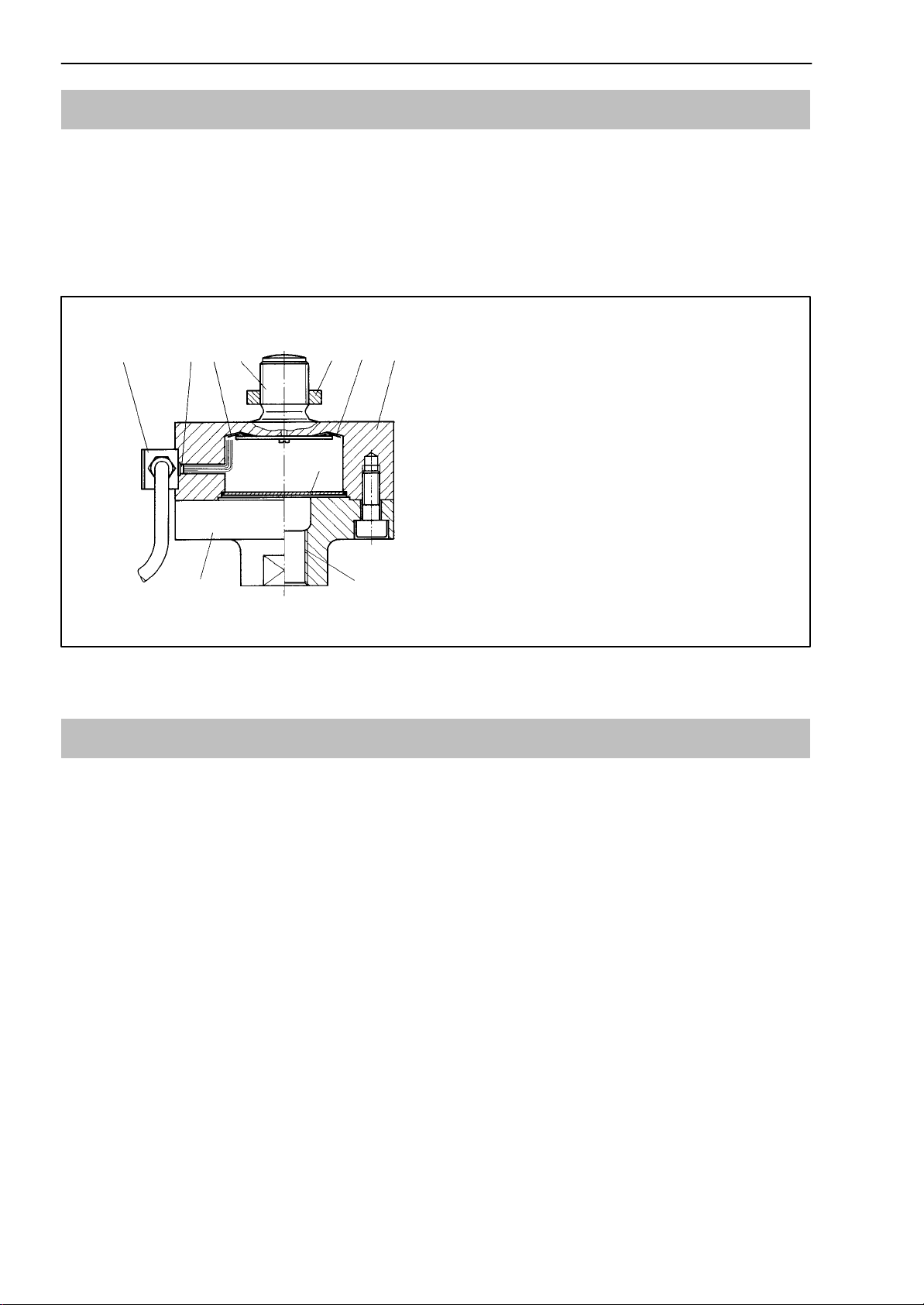
2.2 Housing
The housing with its integral measuring spring is closed by a floor plate
welded to its underside. The measuring spring on the force transducer has a
threaded pin which acts as a force conductor. A removable adapter is
screwed to the lower part of the housing and acts as a force conductor via
jointed eyelets (see Section 7).
12
3
4
57
8
9
61
1 = Strain gauges
2 = Housing with integral measuring spring
3 = Adapter
4 = Lock nut
5 = Threaded pin for force conductor
6 = Glass bushing
7 = Cable chest
8 = Welded cover
9 = Internal thread
Fig. 2.1: Schematic diagram: U2B
2.3 Measurement process, output signal
A force acting upon the transducer will elastically deform the SGs applied to
the measuring body. Their electrical resistance then changes in proportion to
the change in their length. This disturbs the balancing of the measurement
system wired in the form of a Wheatstone bridge, resulting in an output volt-
age UAat contacts 1 and 4 if a bridge excitation voltage UBis present at
points 2 and 3 on the bridge.
The ratio between the voltages, UA/UB, expressed in mV/V, is a measure of
the sensitivity of the force transducer. The change in output voltage UAis lin-
ear to the acting force. Provided the force transducer is connected in accor-
dance with Fig. 5.1 and as specified in the User Manual for the amplifier con-
cerned, compressive forces are displayed with a positive operating sign and
tensile forces are shown with a negative operating sign. The force transducer
is electrically connected in 6-wire mode (see Section 5.2). To reverse the po-
larity, the white and red wires in the cable should be transposed.
SUNSTAR传感与控制 http://www.sensor-ic.com/ TEL:0755-83376549 FAX:0755-83376182 E-MAIL:[email protected]
SUNSTAR自动化 http://www.sensor-ic.com/ TEL: 0755-83376489 FAX:0755-83376182 E-MAIL:[email protected]

9
U2B
HBM 24.5.2000
2.4 Compensating for disturbance variables
The geometry of the measuring body and the positioning of the SGs ensure
that the output signal from the transducer suffers only minimal distortion if the
force being measured is affected by superimposed lateral forces and/or tor-
sional and bending moments. The specifications for this can be found in the
Technical Data. In the interests of greater accuracy, however, it is generally
better to try to prevent spurious loadings of this kind altogether. The U2B also
has separate lateral force compensation which reduces lateral force in-
fluences to a minimum (see Technical Data).
The influence of temperature on the zero signal and sensitivity are compen-
sated. Changes in ambient pressure have the same effect as additive (sub-
stractive) forces (see Section 3.3).
3 Operation on site
3.1 Ambient temperature
For optimum measurement results, keep to the rated temperature range. The
best conditions are constant or very slowly changing temperatures. Measure-
ment errors due to temperature are the result of uneven warming (e.g. radiant
heat) or cooling. A radiation shield and all-round heat insulation provide no-
ticeable improvements. However, they should not be allowed to form any kind
of force leakage.
3.2 Humidity
Extremes of humidity or tropical conditions have no effect on the measure-
ment capability of the transducer, provided they are within the specified limit
values (protection system IP67 in accordance with DIN EN 60529).
Note:
Moisture should not be allowed to penetrate the free end of the connector
cable.
SUNSTAR传感与控制 http://www.sensor-ic.com/ TEL:0755-83376549 FAX:0755-83376182 E-MAIL:[email protected]
SUNSTAR自动化 http://www.sensor-ic.com/ TEL: 0755-83376489 FAX:0755-83376182 E-MAIL:[email protected]

10 U2B
HBM 24.5.2000
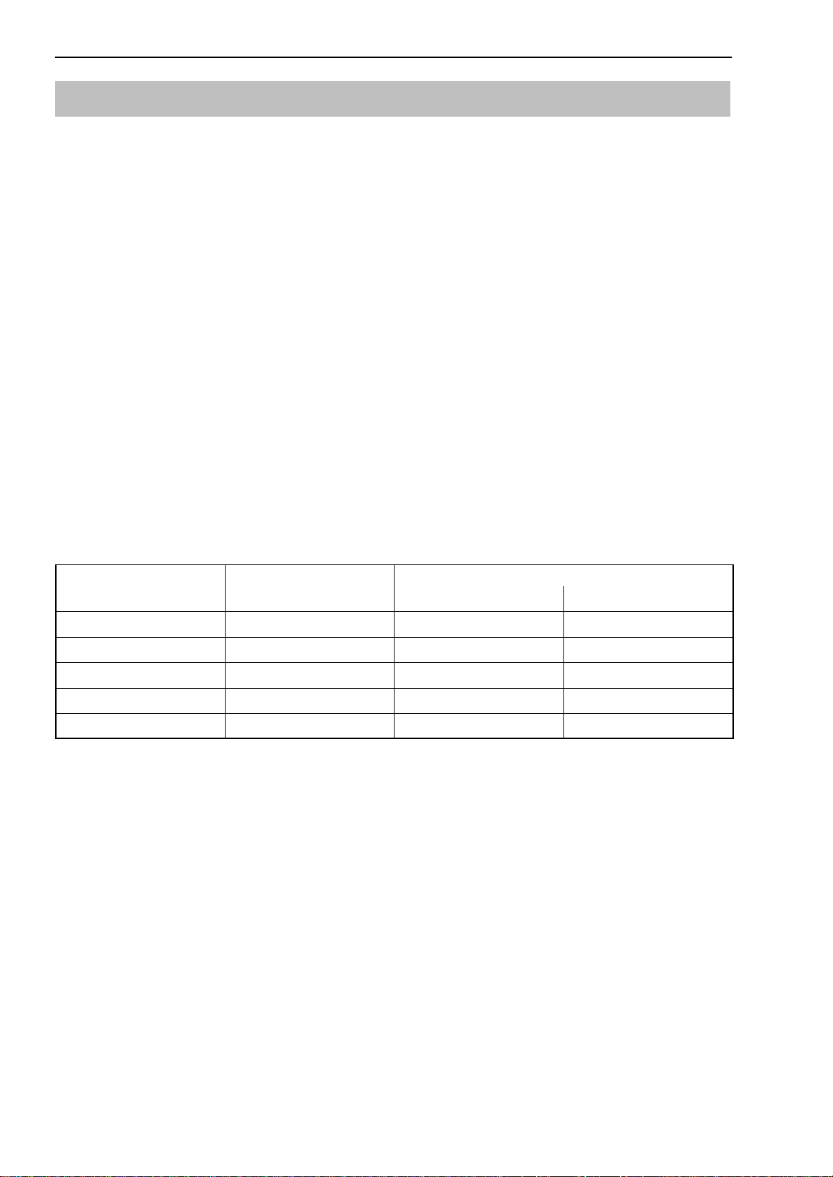
3.3 Ambient pressure
Ambient pressure should be between 0 and 5 bar. Please note that changes
of pressure alter the zero point:
Nennlast 20 kN 500 N 1 kN 2 kN 5 kN 10 kN
Zero point modification
[% sensitivity/10 mbar] ≤±0.004 ≤±0.141 ≤±0.071 ≤±0.035 ≤±0.014 ≤±0.007
Nennlast 50 kN 100 kN 200 kN
Zero point modification
[% sensitivity/10 mbar] ≤±0.002
3.4 Chemical influences
Transducer housings are manufactured from stainless steel. They can be
used in a corrosive environment.
3.5 Contamination
Dust, dirt and other foreign bodies should not be allowed to accumulate to
such an extent that part of the measured force is diverted to the housing so as
to falsify the measured value (force leakage).
SUNSTAR传感与控制 http://www.sensor-ic.com/ TEL:0755-83376549 FAX:0755-83376182 E-MAIL:[email protected]
SUNSTAR自动化 http://www.sensor-ic.com/ TEL: 0755-83376489 FAX:0755-83376182 E-MAIL:[email protected]

11
U2B
HBM 24.5.2000
4 Mechanical installation
4.1 Important precautions during installation
•Handle the transducer carefully.
•Do not overload the transducer.
•During or directly after installation the transducer should be bridged with a
50 mm2stranded copper wire (a highly flexible earth cable (EEK) obtain-
able from the HBM delivery programme). The cable is screwed to the top
and bottom of the transducer. This prevents welding current from flowing
across the transducer and welding the force triggering point.
•Where there is a risk that the transducer might burst and endanger per-
sonal safety if overloaded, additional safety measures need to be taken.
4.2 General installation guidelines
The forces must as far as possible act on the transducer in precisely the di-
rection of measurement. Torsional and bending moments, eccentric loadings
and lateral forces lead to measurement errors, and if the limit values are ex-
ceeded the transducer can be destroyed. Lateral forces include components
corresponding to process quantities that may be obliquely introduced. As an
aid to installation, HBM supplies jointed eyelets for series U2B transducers as
in Section 7. These aids to installation prevent the introduction of torsional
and bending moments as well as lateral and oblique loadings into the trans-
ducer.
SUNSTAR传感与控制 http://www.sensor-ic.com/ TEL:0755-83376549 FAX:0755-83376182 E-MAIL:[email protected]
SUNSTAR自动化 http://www.sensor-ic.com/ TEL: 0755-83376489 FAX:0755-83376182 E-MAIL:[email protected]
12 U2B
HBM 24.5.2000
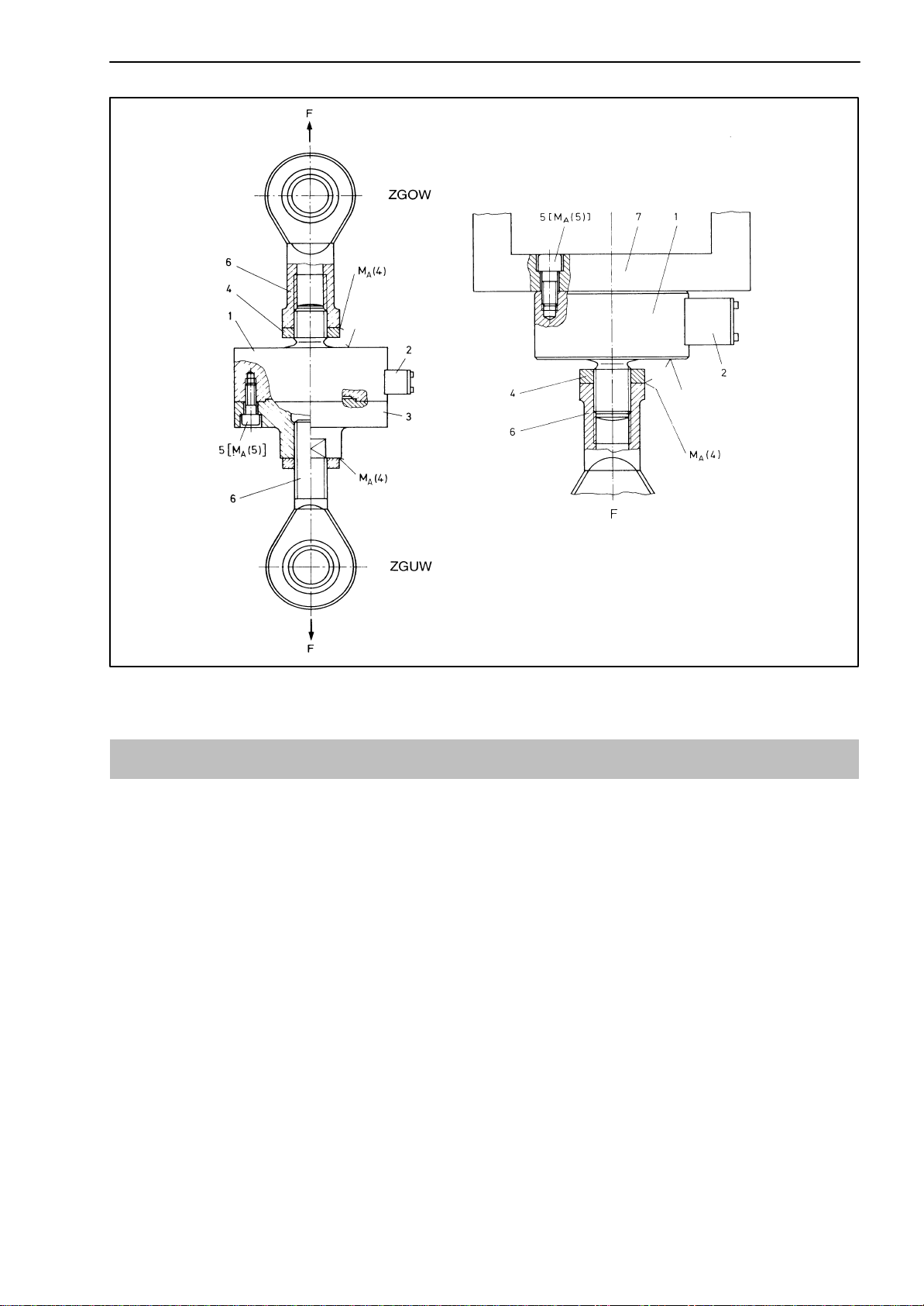
4.3 U2B installation for tensile loading
To introduce tensile loading, there is provision for a threaded pin on top of the
housing and an internal thread on the adapter.
Jointed eyelets are suitable for use in the case of quasi-static loading (stress
reversal 10 Hz). In the case of dynamic loading with a higher frequency,
flexible tension bars should be used.
The adapter (3) can be removed by undoing the screws (5). The transducer
can then be screwed onto the upper part for taking tensile measurements.
Care must be taken to make the bearing surface on the mounting plate flat.
For attachment use screws (5) of at least A2-70 quality (Fig. 4.1). To withdraw
them again use torque MA(5) (see dimension chart). When the adapter is re-
moved the zero signal on the force transducer can change by << 1%. Make
compensating adjustments for this when connecting the electronics. When
measuring dynamic forces, the screw connections to the threaded pin and in-
ternal thread must be properly pretightened when the transducer is free of
load: the tightening torque MA(4) is listed in the dimension chart. It may be ex-
ceeded by not more than 10%. If a lock-nut is used, the torque must on no ac-
count be conducted through the transducer.
U2B Weight Starting torque
Rated force (kN) approx. MA(4) MA(5)
0.5 to 10 0.8kg 60Nm 5Nm
20 2.9kg 300Nm 35Nm
50 4.3kg 500Nm 60Nm
100 10.7kg 2500Nm 60Nm
200 15.9kg 4500Nm 150Nm
SUNSTAR传感与控制 http://www.sensor-ic.com/ TEL:0755-83376549 FAX:0755-83376182 E-MAIL:[email protected]
SUNSTAR自动化 http://www.sensor-ic.com/ TEL: 0755-83376489 FAX:0755-83376182 E-MAIL:[email protected]
13
U2B
HBM 24.5.2000
1 = Transducer
2 = Cable chest
3 = Adapter
4 = Lock nut
5 = Fastening screws
6 = Jointed eyelet
7 = Mounting plate
U2B in
normal position Overhead U2B installation
Fig. 4.1: Installing the U2B
4.4 U2B installation for tensile and compressive loading
The transducers can measure axial forces in torsional as well as compressive
directions. Alternating loads are also captured perfectly. For this purpose the
transducer must be installed without axial play. For dynamic sustained loading
the upper and lower threaded connectors must be pretightened with lock nuts
to more than the maximum load. For this purpose tighten the lock nuts fully
under nominal load in the tensile direction. If a lock-nut is used, the torque
must on no account be conducted through the transducer.
SUNSTAR传感与控制 http://www.sensor-ic.com/ TEL:0755-83376549 FAX:0755-83376182 E-MAIL:[email protected]
SUNSTAR自动化 http://www.sensor-ic.com/ TEL: 0755-83376489 FAX:0755-83376182 E-MAIL:[email protected]

14 U2B
HBM 24.5.2000
5 Electrical connection
5.1 Notes on cabling
Electrical and magnetic fields often cause noise voltage induction in the mea-
suring circuit. This interference arises most commonly from high-power trans-
mission lines running parallel to the measuring circuits, but may also come
from nearby protective contacts or electric motors. Noise voltage induction
can also occur on galvanic paths, especially if the measuring equipment is
earthed at several points.
Please note the following instructions:
•Use only shielded, low-capacitance measuring cable from HBM.
•Lay measuring cable so that it is not parallel to high-tension lines or control
circuits. If this is not possible (e.g. in cable shafts), protect the measuring
cable with e.g. steel conduit and keep it at least 50 cm away from the other
cables. High-tension lines or control circuits should be twisted (15 turns per
metre).
•Stray fields from transformers, motors and protective contacts must be
avoided.
•Do not multi-earth transducers, amplifiers and display devices. All devices
in the measuring system must be connected to the same protection circuit.
•Link the connector cable shield to the transducer housing.
•Connection diagram, earthing scheme (Green-Line)
SUNSTAR传感与控制 http://www.sensor-ic.com/ TEL:0755-83376549 FAX:0755-83376182 E-MAIL:[email protected]
SUNSTAR自动化 http://www.sensor-ic.com/ TEL: 0755-83376489 FAX:0755-83376182 E-MAIL:[email protected]
15
U2B
HBM 24.5.2000
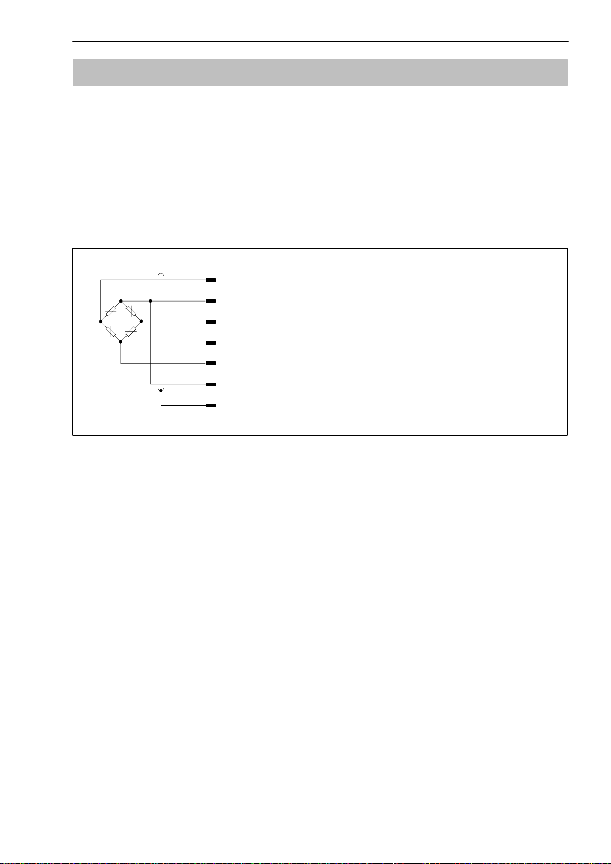
5.2 Six-wire connection
The grey and green wires that are provided in addition to the conventional
four-wire connection pick off the actual value of the bridge excitation voltage
on the transducer and feeds it back to the appropriate measurement electron-
ics. This then corrects the excitation voltage so that the set value is available
to the transducer loss-free. Possible changes in the resistance of the cable
due to temperature or a cable extension are therefore constantly corrected,
even during a measurement. It is therefore possible to extend the cable with-
out any problem.
wh (white)
bk (black)
rd (red)
bu (blue)
gn (green)
gy (grey)
ye (yellow)
Measuring signal (+) UA
Bridge excitation voltage (+) UB
Sensor circuit (–)
Sensor circuit (+)
Bridge excitation voltage (–) UB
Measuring signal (–) UA
Cable shielding, connected to housing
Fig. 5.1: U2B pin assignment
Earthing scheme (Green-Line)
The cable shielding is connected in accordance with the Greenline scheme.
Under this scheme, the measuring system is enclosed in a Faraday cage. In-
side this cage, electromagnetic interference has no effect on the measuring
signal. The transformer section is protected from electromagnetic influences
by special electronic coding procedures.
When there is interference due to potential differences (balance current), the
connections between zero operating voltage and the body of the casing must
be separated on the amplifier and a potential equalisation line must be fitted
between the housing and the amplifier housing (highly flexible stranded wire,
10mm2line cross-section).
SUNSTAR传感与控制 http://www.sensor-ic.com/ TEL:0755-83376549 FAX:0755-83376182 E-MAIL:[email protected]
SUNSTAR自动化 http://www.sensor-ic.com/ TEL: 0755-83376489 FAX:0755-83376182 E-MAIL:[email protected]

16 U2B
HBM 24.5.2000
5.3 Four-wire connection
If the force transducers have to be operated with an amplifier in four-wire con-
nection, then connect the black wire with the grey and the green wire with
the blue. This changes transducer sensitivity by -0.022%. The change in the
temperature coefficient of sensitivity (TKC)) is neglible. Changing the cable
length changes the sensitivity. There is no correction for the effects of temper-
ature on the cable. In fact, even with four-wire connection the accuracy ob-
tained is adequate for many measurement technology requirements.
SUNSTAR传感与控制 http://www.sensor-ic.com/ TEL:0755-83376549 FAX:0755-83376182 E-MAIL:[email protected]
SUNSTAR自动化 http://www.sensor-ic.com/ TEL: 0755-83376489 FAX:0755-83376182 E-MAIL:[email protected]

17
U2B
HBM 24.5.2000
6 Technical Data
Technical Data in accordance with VDI/VDE 2638
Force transducer type U2B
Rated force Fnom kN 0.5 1 2 5 10 20 50 100 200
Accuracy class 0.2 0.1
Rated sensitivity Cnom mV/V 2
Rel. sensitivity variance
Tension/compression dc%<0.2/1.5 <0.2/0.5
Rel. zero signal variance ds,o %<<1
Rel. inversion span
(0.2Fnom to Fnom)u % <0.2 <0.15
Linearity variation dlin %<<0.2 <<0.1
Influence of temperature on
sensitivity/10K
relative to sensitivity TKc% 0.1
Influence of temperature on the
zero signal/10K
relative to sensitivity TK0% 0.05
Influence of eccentricity (1mm) dE% 0.05
Influence of lateral force
(Lateral force 10% Fnom)*dQ% 0.1
Rel. leakage over 30 min dcrF+E %<<± 0.06
Input resistance RiΩ >345
Output resistance RoΩ300...400
Insulation resistance Ris Ω >2⋅109
Reference excitation voltage Uref V 5
Service range of
excitation voltage BU,GT V 0.5...12
Rated temperature range Bt,nom °C –10...+70
Service temperature range Bt,G °C–30...+85 (120***)
Storage temperature range Bt,S °C –50...+85
Reference temperature tref °C +23
Max. operating force (FG) % 130 150
Breaking force (FB) % >300
Static lateral force limit*(FQ) % 25 (100**)
Nominal displacement Snom mm <<0.1 <<0.07 <<0.09
Fundamental resonance fre-
quency fGkHz 4 6 8.7 14 17.5 8 8.5 6 5.6
Weight kg 0.8 2.9 4.3 10.7 15.9
Rel. permissible
vibration loading Frb % 100 160
Protection system in accor-
dance with DIN EN 60529 IP67 (IP68****)
Length of cable, 6-wire connection***** 3m 6m 12m
*relative to a force triggering point 20mm over the membrane
** Mechanical lateral force compensator on request
*** Class 120 version optional
**** IP68 version optional
***** Cable shielding connected to housing
SUNSTAR传感与控制 http://www.sensor-ic.com/ TEL:0755-83376549 FAX:0755-83376182 E-MAIL:[email protected]
SUNSTAR自动化 http://www.sensor-ic.com/ TEL: 0755-83376489 FAX:0755-83376182 E-MAIL:[email protected]
18 U2B
HBM 24.5.2000
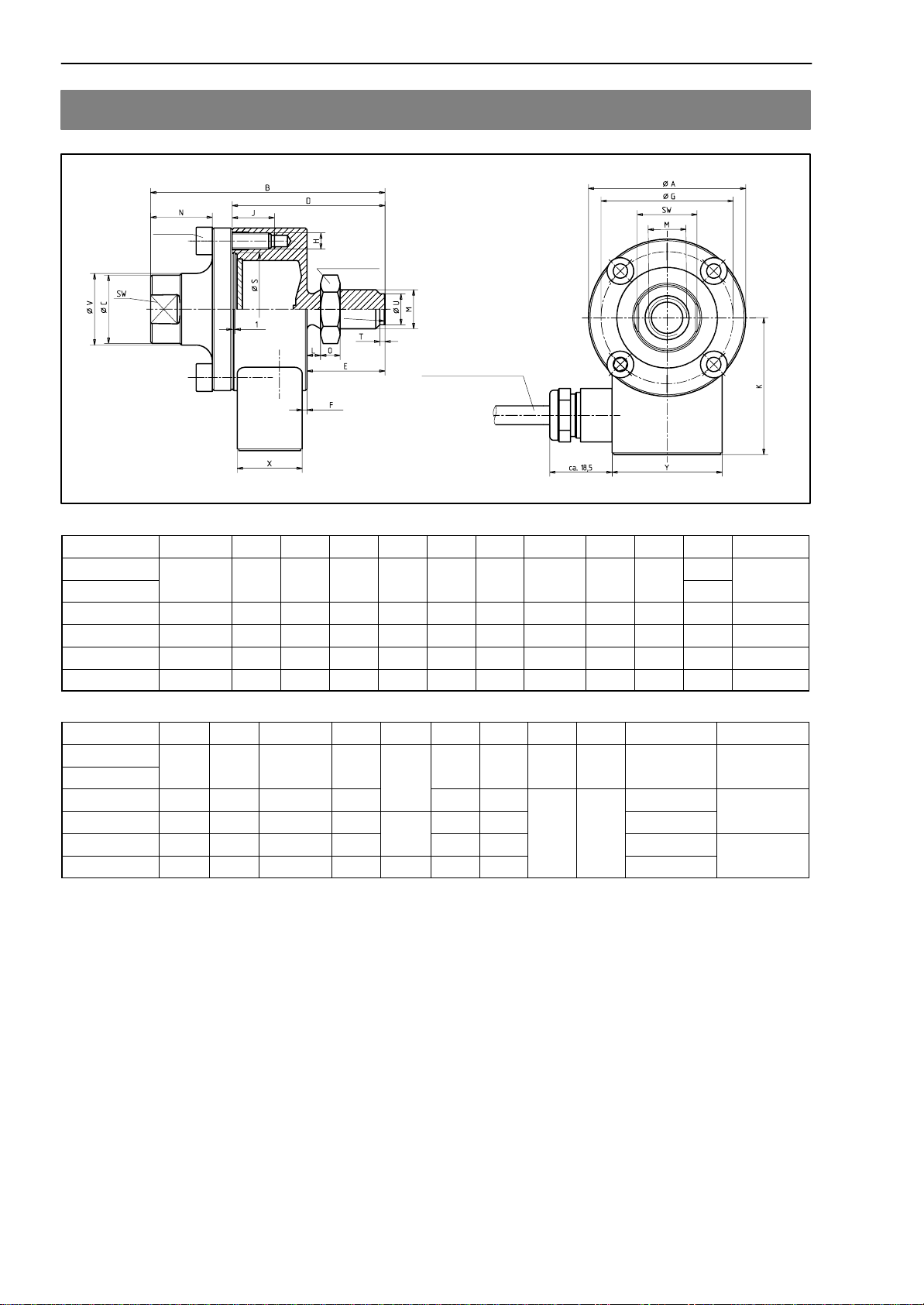
7 Dimensions
drawn off-
sett by 45°
Ball R
Locknut MA
see table
Silicone cable ∅6.5mm
Rated force ∅A–0.2 B∅C D E F ∅G H J K L M
0.5-5kN
50
72
21
47
24
15
42
4xM5
13
43 5
4.2
M12
10kN 50 72 21 47 24 1.5 42 4xM5 13 43.5 7.6 M12
20kN 90 112 33 72 38 2 70 4xM10 20.5 63.5 10.6 M20x1.5
50kN 100 141 40 86 47 6 78 4xM12 19 68 13.2 M24x2
100kN 135 197 68 122 67 17 105 8xM12 16 85.5 19 M39x2
200kN 155 232 82 142 85 19 125 8xM16 26 95.5 24.2 M48x2
Rated force N O ∅Sf8H8 SW T ∅U∅V X Y *MA(Nm) Ball R
0.5-5kN
19
6
34
19
95
22
20
35
60
60
10kN 19 6 34 19 1.6 9.5 22 20 35 60 60
20kN 15 10 55 30
1
.
6
17 34 300
100
50kN 20 12 61 36
2
20 42 30 50 500 100
100kN 29 19 79 60 236 70
30
50
2500
160
200kN 32 22 97 70 2.2 43 84 4500 160
SUNSTAR传感与控制 http://www.sensor-ic.com/ TEL:0755-83376549 FAX:0755-83376182 E-MAIL:[email protected]
SUNSTAR自动化 http://www.sensor-ic.com/ TEL: 0755-83376489 FAX:0755-83376182 E-MAIL:[email protected]
19
U2B
HBM 24.5.2000
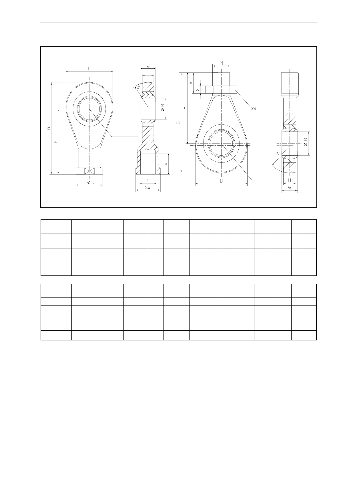
Aid to installation
Jointed eyelet ZGOW Jointed eyelet ZGUW
Material: tempered steel, galvanised; rolled steel and Teflon/bronze fabric foil
Central
bearing ring
Central
bearing ring
Rated force
in kN Order Nr.
Jointed eyelet ZGOW Weight
in kg A∅B D F G H ∅K M SW W
0.5...10 1-U2A/1t/ZGOW 0.2 22 12H7 32 50 66 12 22 M12 19 16
20 1-U2A/2t/ZGOW 0.5 33 20H7 50 77 102 18 34 M20x1.5 32 25
50 1-U2A/5t/ZGOW 0.8 42 25H7 60 94 124 22 42 M24x2 36 31
100 1-U2A/10t/ZGOW 3.2 50 50 +0.002
-0.014 115 151 212.5 28 65 M39x2 60 35
200 1-U2A/20t/ZGOW 4.8 60 60 +0.003
-0.018 126 167 235 36 82 M48x2 70 44
Rated force
in kN Order Nr.
Jointed eyelet ZGUW Weight
in kg A∅B D F G H M SW W X
0.5...10 1-U2A/1t/ZGUW 0.1 33.5 12H7 32 54.5 70.5 12 M12 19 16 7
20 1-U2A/2t/ZGUW 0.2 48.8 20H7 50 79.8 104.8 18 M20x1.5 30 25 9
50 1-U2A/5t/ZGUW 0.4 57.5 25H7 60 94.5 124.5 22 M24x2 36 31 10
100 1-U2A/10t/ZGUW 1.1 65.5 50 +0.002
-0.014 115 148.5 210 28 M39x2 60 35 16
200 1-U2A/20t/ZGUW 3.2 80 60 +0.003
-0.018 126 168 236 36 M48x2 75 44 18
SUNSTAR传感与控制 http://www.sensor-ic.com/ TEL:0755-83376549 FAX:0755-83376182 E-MAIL:[email protected]
SUNSTAR自动化 http://www.sensor-ic.com/ TEL: 0755-83376489 FAX:0755-83376182 E-MAIL:[email protected]
ZGOW
ZGUW
B
A
F
C
20 U2B
HBM 24.5.2000
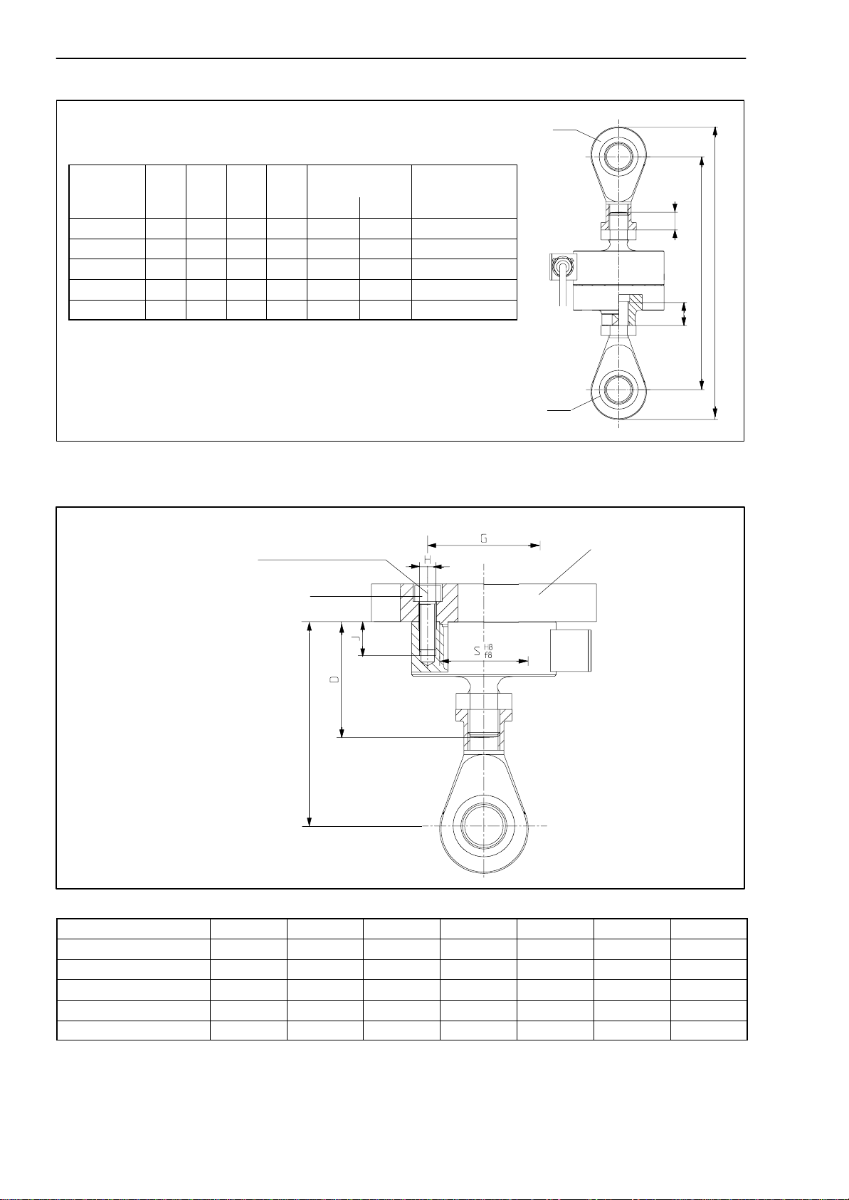
U2B force transducer
complete with jointed eyelets ZGOW, ZGUW
Rated force
in [kN] Amin Amax Fmin Fmax Minimum
screwed-in depth Maximum
screwed-in depth
B C
0.5...10 139 156 171 188 9.6 9.6 25
20 212 234 262 284 16 16 40
50 260 288 320 348 19.2 19.2 55
100 418 436 541 559 27 31.2 75
200 466 489 602 625 36.6 38.4 90
Aid to installation
U2B, with ZGOW, wi-
thout adapter ∅
∅
MA
Base plate,
customer side,
shown
offset 45°or 22.5°
K*
*Recommended mass in relation
to minimum screwed-in depth
Rated force in kN D∅G H J K ∅S MA1) [Nm]
0.5...10 47 42 4xM5 13 84...86.4 34 5
20 72 70 4xM10 20.5 131.6 55 35
50 86 78 4xM12 19 158.2 61 60
100 122 105 8xM12 16 244 79 60
200 142 125 8xM16 26 270.2 97 150
1) Recommended values when using a torque wrench on dry thread
SUNSTAR传感与控制 http://www.sensor-ic.com/ TEL:0755-83376549 FAX:0755-83376182 E-MAIL:[email protected]
SUNSTAR自动化 http://www.sensor-ic.com/ TEL: 0755-83376489 FAX:0755-83376182 E-MAIL:[email protected]
Table of contents
Other Spectris Transducer manuals


