IM-T-277F Jul. 2021
DTK-A Small-size Displacement Transducer INSTRUCTION MANUAL
Thank you for purchasing this KYOWA product. Before using it, please read this
instruction manual carefully. Also, keep the manual within easy reach so that you
can refer to whenever necessary.
Specifications and dimensions described in this manual could be changed
without notice. Please visit our website for the latest version.
1. Calling the operator's attention
The following cautionary symbols and headlines are used to invite the operator’s
attention. Be sure to observe the accompanying precautions in order to
safeguard the operator and preserve the performance of the instrument.
Warning
Improper operation of the system may result in severe
injury of the operator.
Caution Cautions are given to invite the operator’s attention, in
order to avoid instrument failure or mal-function.
2. Important notice
Unless specified, strain-gage transducers must not be used under hydrogen
environment.
3. Safety precautions
Warning
As you push the rod inward, the rod returns to its initial position by reaction
force. Handle the product with care to avoid eye poking.
4. Handling precaution
Caution
Do not apply excessive axial or bending force on the rod.
When changing the gauge head or screws, be sure to insert the
accessory pin(φ2×20)through the hole, located on the cable side of the
rod, to secure the rod in place. Or, the transducer will be damaged.
(Note)
Do not turn the gauge head while
holding the body.
Do not disassemble the product.
Do not use the product under water and dusty environment.
Avoid usage in vibration.
Pay similar attentions toward the product as one gives to regular dial gages.
Always keep the rod clean.
Make sure that the bending radius of cable is longer than 10 times of a
diameter of the cable.
5. Installation
5.1 Fix the transducer to an immovable point as illustrated, using an M6 bolt
and the accessory plate, two M3 bolts. So, arrange the M6 bolt by yourself.
5.2 Initial unbalance with the rod fully extended is approximately -2.5 to -0.5
mV/V.
5.3 Make sure the displacement of about 0.3 mm is applied to the transducer.
5.4 Same as other dial gauges, the probe is made to contact the measuring
point for measuring. However, when a measuring dynamic phenomenon,
that the rod may fail to respond to it on occasion. So make sure before
measuring that it can respond.
5.5 To fix the rod to the measuring point, remove the gauge head then fix to the
measuring point, using the M2.5 screw or the M2.5 screw which is on the
other end of the transducer.
6. Connection
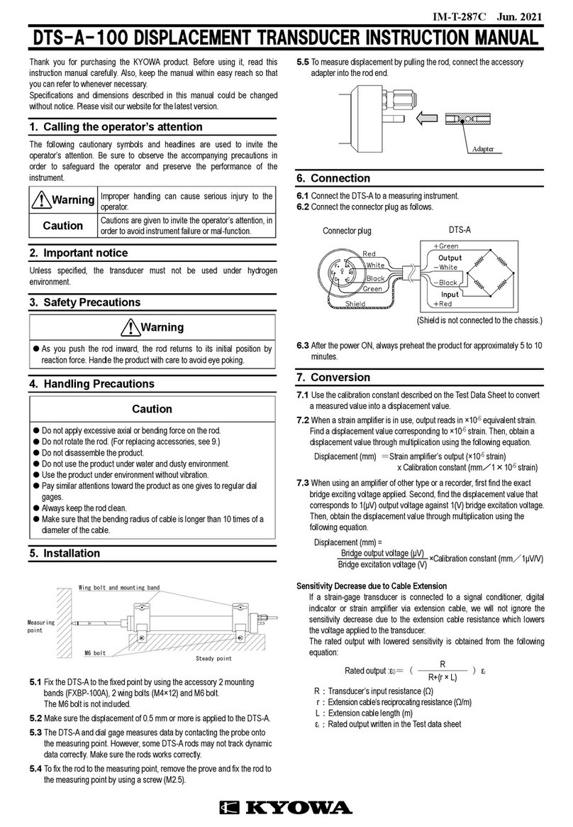
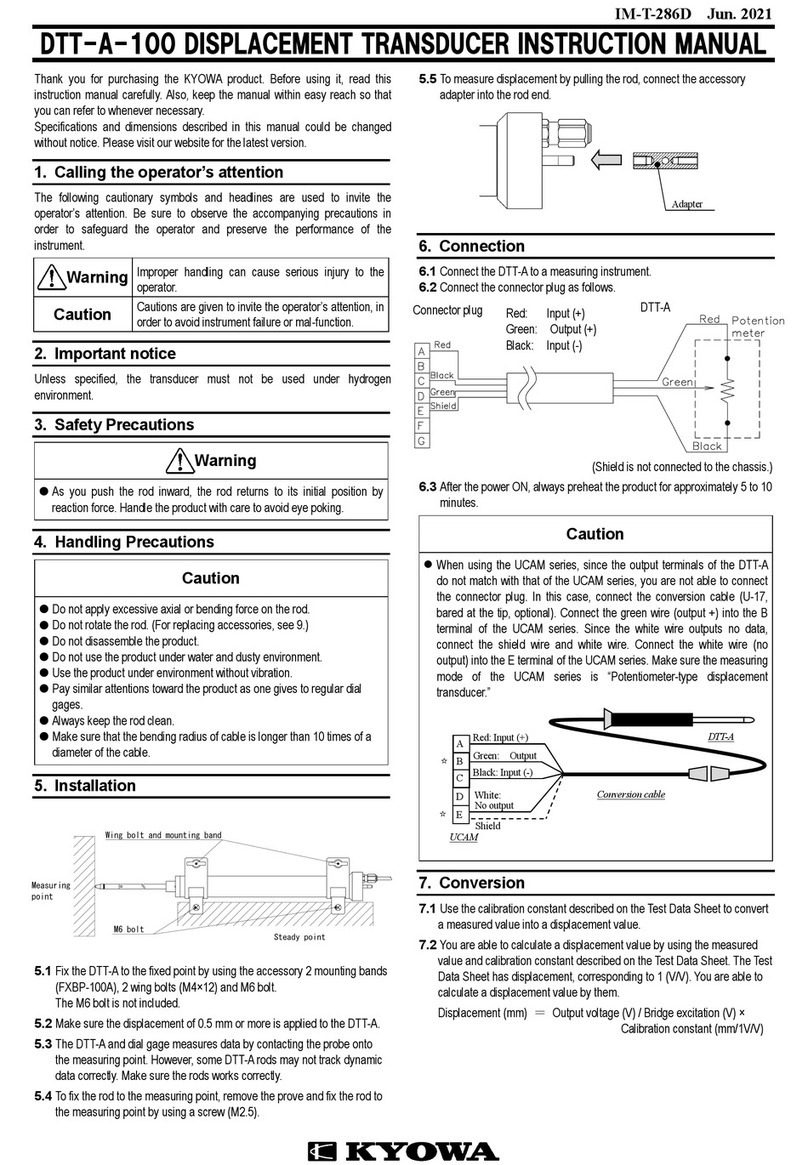
6.1 Connect the transducer to a measuring instrument.
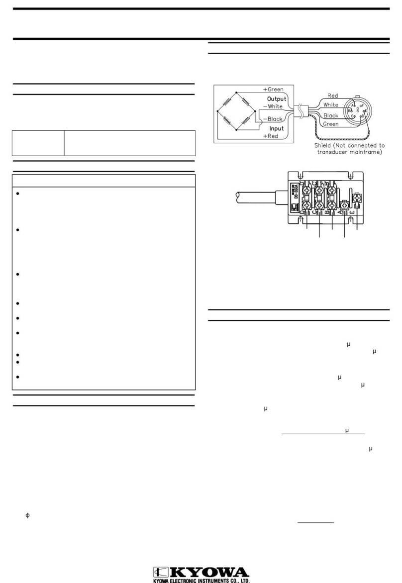
6.2 When using a measuring instrument other than KYOWA, connector plug as
follows.
6.3 After the power ON, always preheat the product for approximately 5 to 10
minutes.
7. Conversion
7.1 Use the calibration constant described on the Test Data Sheet to convert a
measured value into a displacement value.
7.2 When a strain amplifier is in use, output reads in ×10-6 equivalent strain. Find
a displacement value corresponding to ×10-6 strain. Then, obtain a
displacement value through multiplication using the following equation.
Displacement (mm) = Strain amplifier’s output (×10-6 strain)
x Calibration constant (mm/1×10-6 strain)
7.3 When using an amplifier of other type or a recorder, first find the exact
bridge exciting voltage applied. Second, find the displacement value that
corresponds to 1(μV) output voltage against 1(V) bridge excitation voltage.
Then, obtain the displacement value through multiplication using the
following equation.
Displacement (mm) =
Bridge output voltage (μV) ×Calibration constant (mm/1μV/V)
Bridge excitation voltage (V)
8. Storage precautions and inspection
8.1 Avoid water, dust and oil from the product.
8.2 For storage, be sure to put the accessory protection tube on the rod.
8.3 Recommend calibrate the product once a year or so. (Contact your
KYOWA representative.)
8.4 If an abnormal initial value or reading appears, measure input resistance,
output resistance as well as insulation resistance (which should be 100M
or higher).
If abnormal resistance is found, the cause may be failure of the sensing
element. In this case, contact your KYOWA representative.
Caution
To measure insulation resistance, apply a voltage lower than 50V to the
insulation resistance tester.
Pin(φ2×20)
Washer Spring washer
Rod
Gauge head NG!


