Tesla TI2000-009 User manual

Tesla™TI2000-009 Transformer
User Manual
Built Smart...Proven Tough
Power Anytime, Anywhere
Tesla Industries, Inc.
101 Centerpoint Blvd.
New Castle, DE 19720
(302) 324-8910 Phone
(302) 324-8912 Fax
www.teslaind.com

TI2000-009 Transformer
NOTE: All users must read this entire manual prior
to operating the TI2000-009 Transformer.
The TI2000-009 Step Down Transformer is a limited maintenance-free and sealed unit. No repairs are
authorized. Warranty will be voided if unit is tampered with in any way, or if unauthorized repairs are made.
For technical support please contact:
TESLA™ INDUSTRIES INCORPORATED
101 CENTERPOINT BLVD.
CENTERPOINT INDUSTRIAL PARK
NEW CASTLE, DELAWARE 19720
PHONE: (302) 324-8910
FAX: (302) 324-8912
WEBSITE: www.teslaind.com
EMAIL: tesla1@teslaind.com
Improper use or failure to follow instructions in this user manual can result in unit damage and/or injury or
death by electrical shock.
Any attempts to open or examine the inside of the TI2000-009 Step Down Transformer via a tool or device
(borescope, probe, etc.) can result in unit failure and/or injury by electrical shock.
Always protect the unit from short circuit.
No part of this manual may be reproduced or transmitted in any form or by any means, electronic or
mechanical, including photocopying, recording, or any information storage and retrieval system, without prior
written permission from Tesla Industries, Inc.
Copyright © 2014 by Tesla™ Industries, Incorporated. All rights reserved.
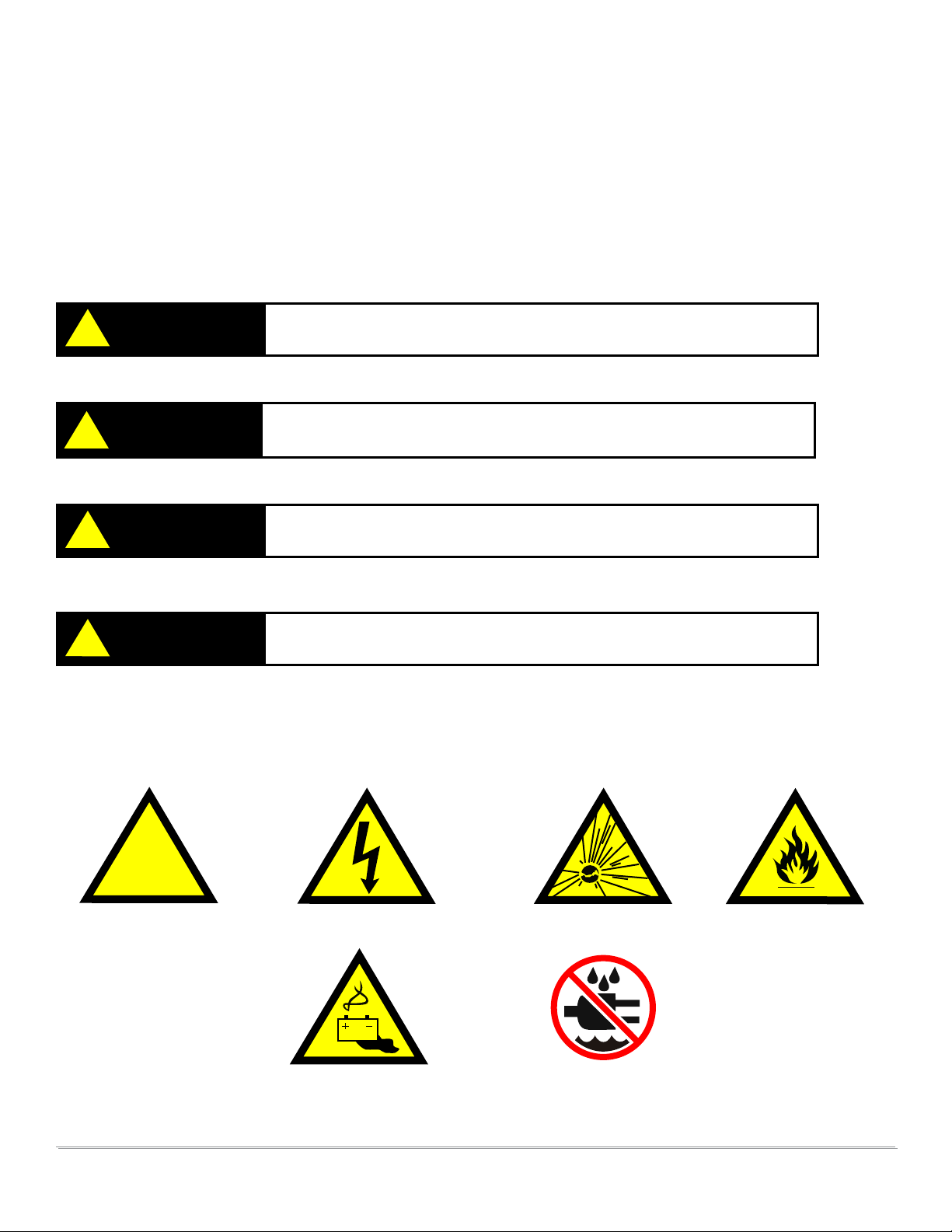
Shock Hazard Potential
CAUTION
02-11-14

TI2000-009 Transformer
Table of Contents
Section 1 – Product Overview 1
1.1 – Introduction 1
1.2 – Use of Words: Shall, Should, May 1
Section 2 – Safety Review 2
2.1 – Safety Notices 2
2.2 – Symbols 2
2.3 – Hazards 3
2.4 – Important Safety Precautions 3
2.5 – Extreme Environments 3
Section 3 – Unit Specications 4
3.1 – General Specications 4
3.2 – Physical Dimensions 4
Section 4 – Features 5
4.1 – Features Overview 5
4.2 – 480 VAC Input 6
4.3 – 280 VAC Output 7
4.4 – Fuses 8
4.5 – Transport Features 9
Section 5 – Pre-Operation 10
5.1 – Maintenance Checks 10
Section 6 – Operating Procedures 11
6.1 – General 11
6.2 – Operating Limits and Restrictions 11
6.3 – Connect to VAC Power 11
6.4 – Connect Ground Power Unit to Transformer 12
6.5 – Connect DC Cable to Ground Power Unit 12
6.6 – Connect DC Cable to Aircraft 13
Section 7 – Post-Operating Procedures 14
7.1 – General 14
Section 8 – Unit Care and Maintenance 15
8.1 – Unit Care 15
8.2 – Normal Functional Test Procedures 16-17
Section 9 –Frequently Asked Questions 18-19
Abbreviations and Denitions 20
Repair Request Form 21

TI2000-009 Transformer 1
Section 1 – Product Overview
1.1 – Introduction
This manual contains the complete operating instructions and procedures for the TI2000-009 Transformer.
The TI2000-009 Transformer is intended for converting 480 three phase VAC to 208 three phase VAC. This
manual makes specic reference to the TI2000-009 Transformer being used as an accessory providing 208
three phase VAC to Tesla Industries Ground Power Units. The observance of procedures, limitations and
performance criteria is essential to ensure peak operating efciency and to maximize operational capabilities
and life of the TI2000-009 Transformer.
Figure 1.1.1 – TI2000-009 Transformer
1.2 – Use of Words Shall, Should and May
Within this technical manual the word “shall” is used to indicate a mandatory requirement for proper operation
and warranty purposes. The word “should” is used to indicate a non-mandatory but preferred method of
accomplishment. The word “may” is used to indicate an acceptable method of accomplishment.

TI2000-009 Transformer
2 3
Figure 2.2.1 – Different types of hazard and caution symbols
General Warning Electrical Hazard Explosion Hazard Fire Hazard
Battery Warning Guard from Moisture
!
Section 2 – Safety Review
2.1 - Safety Notices
Safety notices appear throughout this manual to alert the user to important information regarding proper
installation, operation, maintenance and storage of the TI2000-009. These notices, as illustrated below,
contain a key word that indicates the level of hazard and a triangular icon that indicates the specic type of
hazard.
WARNING Indicates a condition, operating procedure or practice, which if not
adhered to could result in serious injury or death.
CAUTION Indicates a condition or operating procedure, which if not strictly
adhered to could result in damage or destruction of equipment.
DANGER Indicates a condition, operating procedure or practice, which if not
adhered to could result in serious injury or death.
NOTE Indicates a condition, operating procedure or practice, which is
essential to highlight.
2.2 - Symbols
The following symbols will appear within the warning triangles to alert the user to the specic type of danger
or hazard.
!
!
!
!

TI2000-009 Transformer 3
2.3 – Hazards
WARNING SHOCK HAZARD POTENTIAL
Severe injury or death from electrical shock can occur when damp electrical plugs are connected to the
TI2000-009. Make sure the electrical outlet is switched off before making any connections. Failure to
use proper grounding can cause potential shock hazard!
Severe injury or death from electrical shock will occur if either the user
or the TI2000-009 is wet while operating the unit with the 480-208
VAC power source attached. Be sure to disconnect power from the
source if the TI2000-009 has come into contact with water.
2.5 – Extreme Environments
CAUTION UNIT DAMAGE POTENTIAL
The TI2000-009 is equipped with a charger temperature switch that automatically disables AC and
charging functions when the internal temperature reaches above 150°F (65°C). This protects the unit
from overheating and damage. If the unit shuts down, move the unit into a cooler climate such as shade
or air conditioning when possible. Perform a full function test prior to use after the unit has been allowed
to cool.
NOTE: This Transformer is for Indoor use only.
2Safety Review
2.4 – Important Safety Precautions
WARNING FIRE/EXPLOSION HAZARD POTENTIAL
Severe injury or death from re or explosion can occur if electrical sparks are produced near fuel vapors.
To prevent this, make sure electrical outlets are switched to “OFF” position before connecting electrical
plugs. For added safety, this unit shall not be operated during any aircraft fuel handling operation.
!
!

TI2000-009 Transformer
4
Section 3 – Unit Specications
3.1 – General Specications
Electrical
Input Power:
480 VAC / 30 Amps•
3 ø•
60Hz•
15 KVA•
30 Amps Max.•
Class 220°C•
150°C Temperature Rise•
Output: Power
208 VAC•
3 ø•
60Hz•
15 KVA•
70 Amps Max.•
Size:
25.8” long x 19.25” wide x 24.66” high•
655.5mm x 489mm x 626.3mm
Weight
265 lbs (120.2 kg)•
Delta
Wye
3.2 Physical Dimensions
* All dimensions are in inches [millimeters]
SIDE VIEW
FRONT VIEW
TOP VIEW
1
1
2
2
3
3
4
4
5
5
6
6
7
7
8
8
A A
B B
C C
D D
E E
F F
24.89 [632.2]
20.30 [515.6]
26.24[666.6]
22.90[581.7]
14.88[377.9]
9.39 [238.5]
9.03 [229.4]
Front View
Side View Top View
SIDE VIEW
FRONT VIEW
TOP VIEW
1
1
2
2
3
3
4
4
5
5
6
6
7
7
8
8
A A
B B
C C
D D
E E
F F
24.89 [632.2]
20.30 [515.6]
26.24[666.6]
22.90[581.7]
14.88[377.9]
9.39 [238.5]
9.03 [229.4]
SIDE VIEW
FRONT VIEW
TOP VIEW
1
1
2
2
3
3
4
4
5
5
6
6
7
7
8
8
A A
B B
C C
D D
E E
F F
24.89 [632.2]
20.30 [515.6]
26.24[666.6]
22.90[581.7]
14.88[377.9]
9.39 [238.5]
9.03 [229.4]

TI2000-009 Transformer 5
Section 4 - Features
4.1 – Features Overview
The TI2000-009 is designed to convert 480 VAC three phase to 208 VAC three phase. The unit’s exterior
features an input receptacle, an output receptacle, and wheels for transport. The inside of the unit features
replaceable fuses.
1
2
208 Three Phase Output1.
480 Three Phase Input2.
Locking Casters3.
3

TI2000-009 Transformer
6
4Features
4.2 – 480 VAC Input
The 480 Three Phase VAC input cable is twenty feet long with a plug.
Figure 4.2.1 480 VAC Input cable location
CAUTION Unit may be damaged if incorrect AC power is applied. Check to make
sure the unit is plugged into 480 phase VAC.
!
Figure 4.2.2 480 VAC cable plugged in.

TI2000-009 Transformer 7
4
Features
4.3 – 280 VAC Output
The TI2000-009 has a 208 three phase VAC output located on the top of the unit. The output is a female
receptacle and is used for plugging in the TI4200 GPU-24, TI4400 GPU-24, TI5200 GPU-24, or TI5400 GPU-
24 male plug.
Figure 4.3.1 208 VAC Input cable location
Figure 4.3.2 208 VAC receptacle. Figure 4.3.3 208 VAC cable
plugged in.

TI2000-009 Transformer
8
4Features
4.4 – Fuses
To protect the unit from damage there are three fuses inside the unit. In order to replace the fuses the unit
must be opened. The TI2000-009 has a three 30A 600V fuses located on the backside of the front panel.
Check with multimeter to ensure the fuses are blown before replacing.
CAUTION Be sure unit is completely disconnected from power before opening unit.
NOTE: This is the only repair authorized for the user. For all other repairs please contact Tesla’s
Customer Service Department at (302) 324-8910 with any questions or concerns.
!
Figure 4.4.1 Replaceable Fuses

TI2000-009 Transformer 9
4
Features
Figure 4.5.1 Handle and Wheel Locations
Figure 4.5.2 Transformer Handle Figure 4.5.3 Lockable Casters
4.5 – Transporting Unit
The TI2000-009 has a telescopic handle that makes it easy to roll or push the unit. It is also equipped with
four wheels.
Handle
Lockable casters
Lockable Casters and Handle.
The Transformer is equipped with a handle and four lockable casters. The transformer can be maneuvered on
all four or you can remove the wheel base and mount the transformer to a solid surface (wall, oor, etc.).

TI2000-009 Transformer
10
Section 5 - Pre-Operation
5.1 –Maintenance Check
Before operating the TI2000-009 check for any signs of damage or wear to the unit, tires, cables and
plugs.
Check Unit
Check the unit for dents, punctures, case distortion or mis-alignment, cracked or loose connectors. If no
external damage is evident user may proceed. If damage is evident contact Tesla Industries.
Check Casters
The TI2000-009 is equipped with four lockable casters. Before moving the transformer, make sure all four
casters are unlocked so it can properly be moved to the desired location.
Check DC Power Cable And AC Power Cord For Damage
Crushed or torn cables will need to be replaced, before any operations can occur.
Check DC Power Cable/Connections For Damage
Check connectors for cracks, cuts, distortions, excessive wear, broken/loose fasteners and cable attachment.
Replace contacts or entire plug if necessary.

TI2000-009 Transformer 11
Section 6 - Operating Procedures
6.1 – General
This section denes the operating procedures, which includes all steps necessary to ensure safe and efcient
operation.
Correct operation of the TI2000-009 includes both pre-use and operational checks of the unit. Knowledge
of the operating limits, restrictions, performance, unit capabilities and functions is fundamental to correct
and safe operation. The operator shall ensure compliance with the instructions in this manual that affect
operational safety and the warranty of the unit.
6.2 – Operating Limits and Restrictions
The minimum, maximum and normal operating ranges result from careful engineering and evaluation of test
data. These limitations must be adhered to during all phases of operation.
WARNING FIRE/EXPLOSION HAZARD POTENTIAL
Severe injury or death from re or explosion can occur if electrical sparks are produced near fuel vapors. To
prevent this, make sure electrical outlets are switched to “OFF” position before connecting electrical plugs.
For added safety, this unit shall not be operated during any aircraft fuel handling operation.
6.3 – Connect to VAC Power
Plug the transformers VAC input plug into the appropriate 480 three phase VAC outlet. All three phase lights
will come on. If all three lights do not activate then there is a problem with the AC power source. Disconnect
the unit and troubleshoot the power source.
CAUTION
!Unit may be damaged if incorrect AC power is applied. The transformer
must be plugged into a 480 three phase VAC power source.
Figure 6.3.1 Transformer connected to VAC Power

TI2000-009 Transformer
12
6Operating Procedures
6.4 – Connect Ground Power Unit to Transformer
NOTE Before plugging the unit into the Transformer switch the GPU’s input
power circuit breaker to the “OFF” position.
The TI5400 400HZ GHMD can then be plugged into the transformer’s output socket. Once the plug is securely
in place, the input power circuit breaker can be switched to the “ON” position.
Figure 6.4.1 Transformer connected to GPU
6.5 – Connect DC Cable to Ground Power Unit
The chances of accidental arching are low, but for added safety, press the DC Output “OFF” button. Ensure power cable
connector is fully seated into the DC output receptacle.
Figure 6.5.1 DC “ON/OFF” buttons
location.
Figure 6.5.2 DC “ON/OFF” buttons.
Figure 6.5.3 DC cable plugged into GPU.
!

TI2000-009 Transformer 13
6
Operating Procedures
6.6 – Connect DC Cable to Aircraft
To prevent arching while connecting DC power to the aircraft, press the DC output “OFF” button, then connect
DC power to the vehicle. Ensure ground power cable connector is fully seated into aircraft receptacle. When
you are ready to supply DC power, press the DC output “ON” button and it will illuminate. DC bus power
should come on and the aircraft’s voltmeter should indicate 23.5 to 24 VDC (23 VDC minimum).
Starting Aircraft Engine
Check power cable for security and correct installation prior to engine start. Follow ground power unit engine
starting procedure as specied in aircraft operator’s manual.
Figure 6.6.1 Connecting DC cable to aircraft and starting engine

TI2000-009 Transformer
14
Section 7 - Post-Operating Procedures
7.1 – General
When not in use, the TI2000-009 Transformer should be covered and stored in a dry, temperature controlled
area. Protect the unit from the elements and man-made hazards whenever possible. Make sure to keep the
transformer’s receptacle, plugs and air vents clear of debris. Disconnect unit and allow cooling time.

TI2000-009 Transformer 15
Section 8 - Unit Care and Maintenance
8.1 – Unit care
Avoid Prolonged Exposure to Extremely Damp Environments
Be sure to disconnect AC power from the AC source if the TI2000-009 has come into contact with water. If
the fuse has tripped due to water seepage, allow the unit to dry out before attempting to replace. Cover the
unit to prevent water seepage. If the unit is operated in extremely damp conditions, it should be stored in an
environmentally controlled building when not in use. Wipe unit clean periodically with a soft cloth to remove
dust, dirt, etc.
Protect Cables from Damage
Do not cut, crush, or drag the input or output power cables when handling the TI2000-009. Always inspect
cables prior to use. If no damage is evident, proceed to the next step. If damage is evident, contact Tesla™
Customer Service. Do not attempt to use any other type of power cables other than the Tesla™ cables
included with the transformer.
DANGER Severe injury or death from electrical shock will occur if either the user or the TI2000-009
is wet while operating the unit with an AC power source attached.
CAUTION Damage may occur if an unapproved or modied AC line cable or input plug is attached to
the GPU. Do not use any type of AC voltage converter.

TI2000-009 Transformer
16
8Unit Care and Maintenance
8.2 – Normal Function Test Procedures
This section deals with “normal function” test procedures, and includes all
steps necessary to ensure that the TI2000-009 is operating within specied
parameters prior to use. A digital multimeter (an example is shown in
Figure 8.2.1) capable of measuring DC and AC voltage and resistance will
be required to perform some of the tests. These functional test procedures
should become routine.
Figure 8.2.1 – Digital Multimeter
Check Unit for Evidence of Damage
Check for dents, punctures, case distortion or misalignment, and cracked or loose connectors. If no damage
is evident, proceed to the next step. If damage is evident, contact Tesla™ Industries, Inc.
Figure 8.2.2 – Damaged Unit
Misaligned Case with Bent
Faceplate

TI2000-009 Transformer 17
8
Unit Care and Maintenance
Check Unit Internal Resistance (Test for Shorts)
This section deals with “normal function” test procedures, and
includes all steps necessary to ensure that the transformer is
operating within specied para meters prior to use. A digital
multimeter (an example is shown in Figure 8.2.1) capable of
measuring DC and AC voltage and resistance will be required
to perform some of the tests. These functional test procedures
should become routine.
1. Place the negative probe on the re-
ceptacle’s left ground insert and
the positive probe on top side phase
1 insert.
2. Move the positive probe to the right
side phase 2 positive insert.
3. Move the positive probe to the lower
phase 3 positive post.
1. Move the negative probe to the up-
per phase 1 probe and the positive
probe to right side phase 2 probe.
2. Move the positive probe to the lower
phase 3 positive post.
Check Unit Approximately 120 VAC
Check Unit Approximately 208 VAC
3. Move the negative probe to the right
side phase 2 probe and the positive
probe to lower phase 3 probe.
Table of contents
Other Tesla Transformer manuals
Popular Transformer manuals by other brands

audiodinamica
audiodinamica SUT 3 instruction manual

B-K lighting
B-K lighting CamLock UPM PM1RM installation instructions

LUMIEN
LUMIEN TR-250 installation guide

ambiance
ambiance HC-669 Installation and safety instructions

Lutron Electronics
Lutron Electronics Sivoia QED SV-100SF-JBOX installation instructions

Siemens
Siemens MICROMASTER 440 Maintenance Instruction