TeSuCo Oxyturbo Nitrogen 6000 User manual

1
Operating Instructions
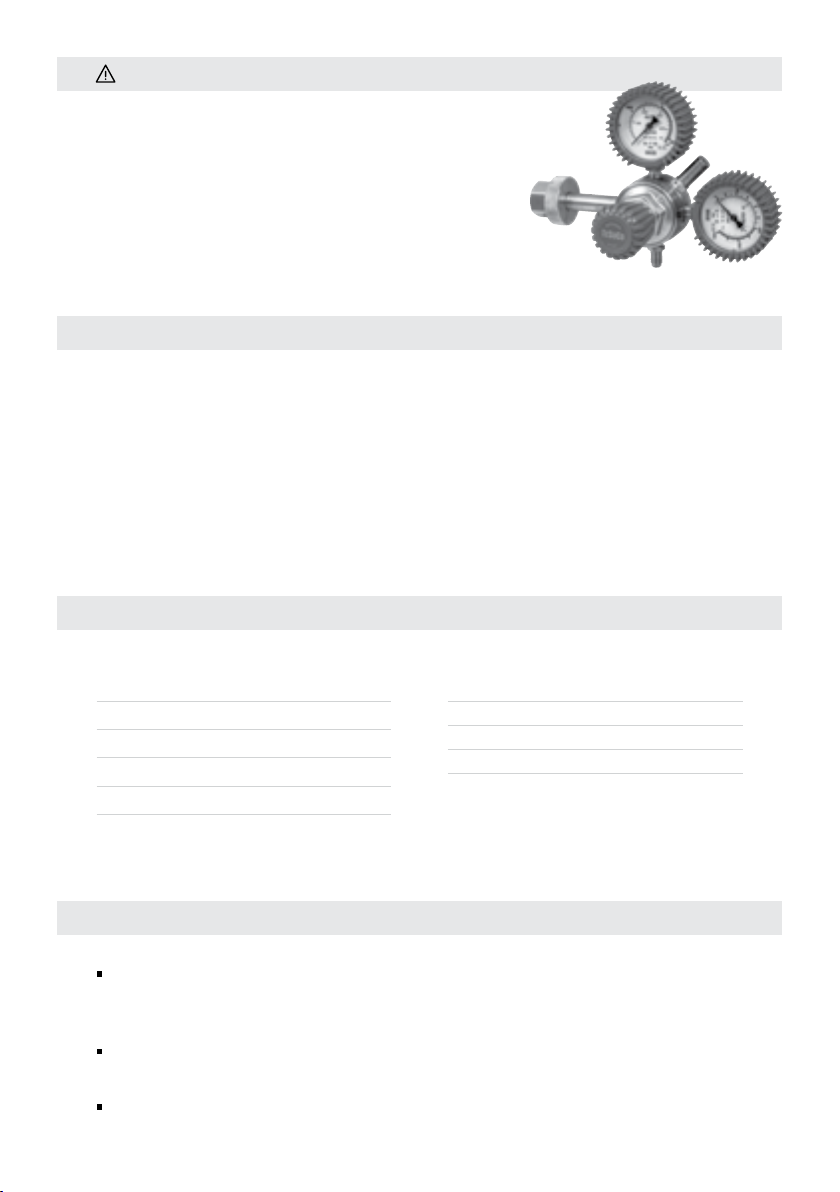
Nitrogen 6000 Regulator
HVAC-R High Flow
www.tesuco.com.au
QUALITY GAS EQUIPMENT
2
CAUTION
1. FUNCTION
TECHNICAL DATA
Read the following instructions carefully before using the
pressure regulator, and keep them for future reference.
The instructions provide all the information necessary
for correct use of the instrument, to avoid damage and
danger. Tesuco®/OxyTurbo is not responsible for any
damage occurring due to incorrect use of the instrument,
or to modifications made to it.
The function of the pressure regulator is to reduce and stabilize the pressure of a gas; the
regulator changes the pressure at which the gas is kept in the cylinder into the pressure
needed to use for the application.
The pressure regulator has been designed so as to be used only and exclusively with the
type of gas and at the pressures which are shown by the marking.
To try and use the pressure regulator with types of gases and pressures other than those
indicated can be dangerous.
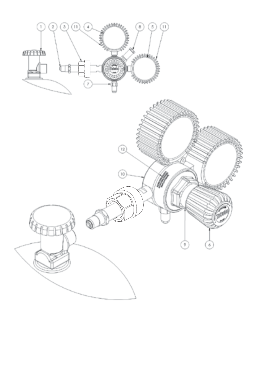
1. Cylinder valve
2. Inlet connection "O" ring (seal)
3. Inlet connection (nut & stem)
4. High pressure gauge
5. Low pressure gauge
6. Pressure adjusting knob
7. Outlet connection
8. Adaptor 1/4 - 5/16
9. Relief valve
10. Bonnet
11. Body
12. Gauge protectors
13. Markings
PARTS LIST (See page 7)
P1 = Inlet Pressure P2 = Outlet Pressure Q1= Maximum Delivery Flow Rate
Gas N2
Colour Blue
ID N
P1 kPa 30,000
K-Class -
P2 kPa 6,000
Q1 m³/h 50
Nitrogen 6000

3
2. ASSEMBLY
3. INSTRUCTIONS FOR USE
1. FUNCTION
2.1 Connection of the Pressure Regulator
Check that the pressure regulator is correct both for the type of gas and the pressure in
the cylinder in use.
Turn the pressure adjusting screw (6) anticlockwise, to check that the pressure regulator
valve is closed.
Replace the "O" ring (2) if it is damaged every time you change the cylinder.
Before screwing on the pressure regulator, briefly open the cylinder valve (1) then close
to remove any impurity, in case using compressed air. Pay attention to direct the cylinder
outlet towards a wall and far from heating sources.
During this operation it is dangerous to stand, or place your hands in front of the
cylinder valve (1).
Position the pressure regulator with the gauges the right way up.
Screw the inlet connection (3) tightly to the cylinder valve, by hand or by using a spanner.
3.1 Opening
Slowly open the cylinder valve (1). The high pressure gauge (4) will show you the
cylinder pressure.
Opening the cylinder valve too quickly may make gauges malfunction.
Open the pressure adjusting screw (6) very slowly. The low pressure gauge (5) will show
the outlet pressure.
CAUTIONS
Incorrect use of the pressure regulator can cause serious damage. Users must
be trained by competent people.
The pressure regulator must be treated as a precision instrument. Protect it from
accidental knocks, dust, oil and other sources of dirt.
Do not use the pressure regulator if it is not in perfect working condition (see 5.1).
When you draw gas, the cylinder must be placed upright and protected from falling.
4
CAUTIONS
Before opening the cylinder valve (1), check carefully that the regulator is
completely closed (turn the pressure adjusting screw (6) anticlockwise).
3.2 How To Regulate Pressure
To increase pressure: slowly turn the regulator pressure adjusting screw (6) clockwise.
To decrease pressure: slowly turn the regulator pressure adjusting screw (6) anticlockwise.
CAUTIONS
Using the pressure adjusting screw (6) it is possible to compensate an eventual
pressure drop.
Outlet pressure must not be regulated higher than the pressure you need to use
when flowing.
Outlet pressure must not be regulated higher than the red mark on the low
pressure gauge (5).
3.3 Closing
Close the cylinder valve (1).
Release the gas until the regulator gauges indicate "zero".
Turn the pressure adjusting screw (6) anticlockwise till it is completely closed.
3. INSTRUCTIONS FOR USE
The pressure regulator must be treated as a precision instrument.
When the pressure regulator is not to be used for long periods, store it in its wrapping or
in its box , to prevent contact with dust, oil and other sources of dirt.
Do not carry out maintenance or repairs, other than the following.
Use only original OxyTurbo spare parts and accessories.
Spare parts are available also from your retailer.
In case of failures which cannot be repaired following these instructions, take your
pressure regulator back to the retailer.
4. STORAGE
5. MAINTENANCE

5
Dispose of the regulator in accordance with local requirements.
Do not clean gauge glasses with petrol, solvents or any other kind of detergent.
5.1 Malfunctioning
In case of malfunction (e.g. leaks in the gauges or in the relief valves) stop use and close
the cylinder valve (1) immediately.
Unless there is visible damage to the outside of the instrument, we suggest that the
pressure regulator be returned to the supplier to be checked and repaired.
CAUTIONS
Do not use the pressure regulator if there are the following malfunctions:
The "O" ring (2) is damaged or lost.
The pressure regulator or any of its parts (gauge, inlet connection, outlet
connection) are damaged or dirty, oily etc.
There are any leaky connections.
The relief valve adjustment has been modified or the valve leaks.
5.2 Relief Valve
For safety reasons, the pressure regulator is equipped with an excess pressure valve.
In case of malfunctioning, this valve allows the excess gas pressure to vent.
CAUTIONS
Do not modify the calibration of the relief valve.
5.3 Checking The Seal
This check must be carried out only in the open air: use either soapy water or a gas leak
detector (Gas Control Part No: OTLDS). Do not use flames.
Spray detector on the area to be checked.
The forming of bubbles or foam is a sign of a leak.
6. INSTRUCTIONS FOR DISPOSAL
5. MAINTENANCE
6
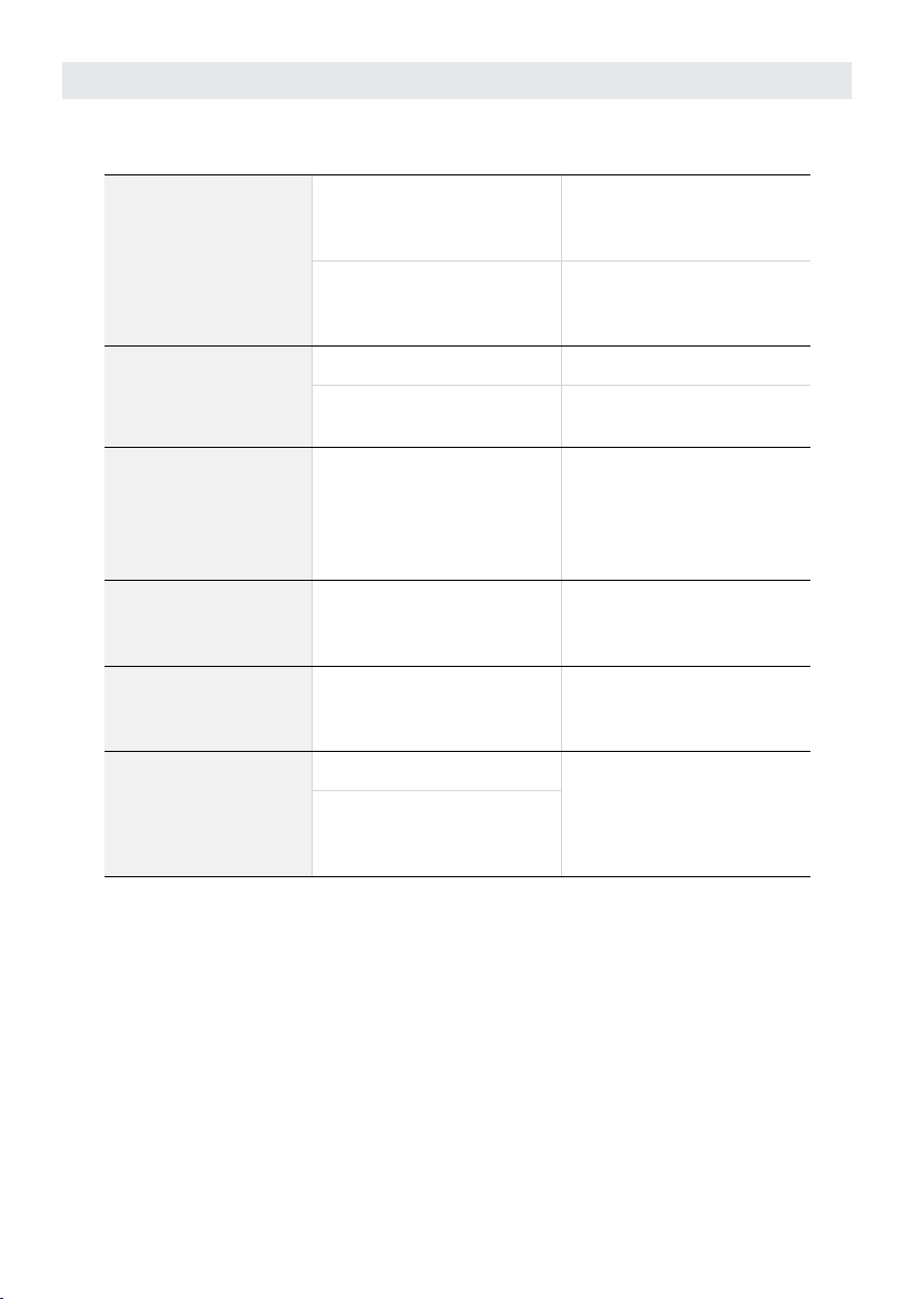
7. MANAGING FAULTS
PROBLEM CAUSE SOLUTION
Cannot connect to
the cylinder.
Incorrect inlet connection.
Only use correct cylinder
connection for the gas
type from AS 2473.2.
Inlet connection damaged.
Replace the inlet
connection with a
genuine part.
Insufficient gas flow.
Regulator undersized. Contact supplier.
Blocked or damaged
equipment downstream. Replace the equipment.
Gas Leak. Connection error.
Release the control knob,
tighten the connections
and re-check. Apply
pressure again, if leak
persists, repair or replace.
Increase in output
pressure, when not
flowing.
Leak through the regulator
seat valve.
Replace the
encapsulated seat.
Unstable output
pressure. Flow rate to high.
Check the flow of the
regulator matches the
requirement.
Vibrations
Flow rate to high.
Limit the flow with
the control knob or a
restricted oriface.
Presence of a quick
opening valve in
downstream equipment.
Note: Any repairs to regulators must be done with genuine OxyTurbo parts by a
qualified technician.
7
Note: Some of the details in the illustration may differ from those of the appliance
supplied. This company reserves the right to modify the product without prior warning.

8
The information contained herein is provided to assist the operator in the safe
use of a Tesuco®Nitrogen 6000 Regulator. However, the ultimate responsibility
for the safe use of this and any attached equipment lies solely with the operator,
including any requirements of associated Australian Standards.
OI_RC1SNI60C_V01
Table of contents
Other TeSuCo Controllers manuals

Popular Controllers manuals by other brands

Emerson
Emerson Fisher 3024S instruction manual

Mitsubishi
Mitsubishi AL2-2PT-ADP installation manual

Sherwood Scuba
Sherwood Scuba maximus SRB5600 Assembly & maintenance guide

Chamberlain
Chamberlain AGO250L instructions

Supreme Heating
Supreme Heating Aqua-Gen 2 instructions

Danfoss
Danfoss EKC 347 instructions


