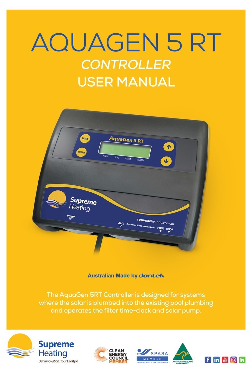
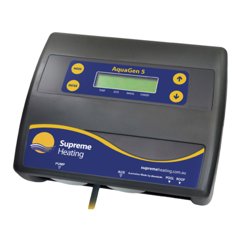
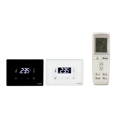
Supreme Heating Aqua-Gen 2 User manual

Aqua-Gen 2 INSTRUCTIONS
DESCRIPTION:
The Aqua-Gen 2 is an entry range automatic solar controller with temperature adjustment, manual
mode and winter mode features. Mode of operation and the temperature limit setting are retained after
a power outage.
CONTROLLER INSTALLATION:
Find a suitable location to mount the control box. The controller must be installed out of direct weather
and no closer than 3m from the waters edge. Lift up the two mounting tabs and use two appropriate
screws to mount the control box to the wall, keeping in mind that the power cable is 1.8m long and
should be plugged directly into a general power outlet, not into an extension lead.
The solar pump plugs into the 240Vac socket marked as PUMP.
The pool sensor must be fitted into the suction line of the pump, as close to the pool as practical,
preferably in a position out of direct sunlight. It is recommended that a 14.5mm hole be drilled in the
PVC pipe, this can be carried out using a Dontek PD01 grinding drill or a small pilot hole can be drilled
and a 14.0mm drill-bit used spinning in a counter clockwise direction to minimise the chance of
shattering pipe. Insert the grommet into the pipe and gently push in the black sensor barb. The green
sensor plug is to be fitted to the plug socket marked POOL.
DO NOT cable-tie or tape sensor wires to mains power. In some cases there is some benefit to cable
tie 30cm of wire from the sensor to the pipe and insulate this section (some ambient differences can
travel up the copper wire and affect the sensor reading).
Roof sensors must be fitted into a small piece of solar collector or equivalent and attached to the roof.
The best location is within arms length of the gutters edge of the house or shed as long as the sensor
end is not shaded and is on a roof of similar aspect of the main collector. It must not be fitted on top
of the solar collector or fitted to high points on the roof like Ridge Capping as false readings will be
detected.
Keep in mind that it is of the utmost importance to keep the roof sensor as short as possible as this will
assist in the longevity of the sensor and controller in the event of electrical storm activity and power
surges. Sensor cables must not be run parallel to power cables and run lengths should be less
than 50m. Cable ties should be used to fasten the sensor cable to the cold water inlet pipe making
sure that the ties are approximately 10mm from PVC fittings. Cable ties should be tightened only firm,
over tightening can cause breaks in the outer PVC if not careful. If the cable is to be run under ground
a conduit must be used to protect the wire and there is to be no cable joins within, conduit ends must
be sealed to prevent water ingress. Any excess cable should be removed and re-fitted ensuring
that the wire ends are tinned with solder. The sensor plug is to be fitted to the right hand socket
marked ROOF.
NOTES:
1. If a sensor fault is detected the controller will display which sensor failed (POOL and/or ROOF)
and the type of failure.
2. Should power be interrupted for any reason, the controller will resume normal operation when
power is restored, all information will have been kept.

3. Temperature sensor used with this unit is digital and is accurate to 0.5°C, no calibration is
required.
4. The sensor cable with the thin trace is the positive and is usually fitted to the right hand side of
the green plug when looking at the plug screws, incorrect polarity will be displayed as an S/C fault
(short circuit).
5. If the controller has stopped pumping and is displaying a higher temperature than expected it
may be caused by a pump which is failing to prime, check the pump and if necessary prime the
pump as per the pump manufacturers’ instructions then reset the controller by turning it off/on.
6. Maximum rated output load for the 240V sockets is 10 Amps 2400 Watt.
CONTROLLER OPERATION & SETTINGS
TEMPERATURE LIMIT:
To change the temperature limit the pool is heated to before the pump stops, simply press the UP
button to increase or the DOWN button to decrease the desired temperature, increasing the
temperature will not increase the heat output as it is dependent on the amount of collector and
available heat from the sun.
The controller will automatically choose to run the pump based on solar gain (i.e. sun shining & roof is
hot). Once the desired temperature is achieved the pump is stopped and a 4 hour wait commences to
ensure no energy is wasted by cycling the pump.
If after 4 hours the roof is hot enough then the pump may start to provide another heating cycle and if
the desired temperature is reached again then no heating will occur until the next day.
MANUAL PUMP MODE:
Holding the UP button to go above 40°C will toggle the pump from Off to On or vice versa, Manual
mode will time out after 30 minutes of being selected, with a default temperature limit of 30°C. It is also
a good way of checking the installation on a cold or cloudy day.
WINTER MODE:
Winter mode of operation is for off-season maintenance or if pool heating is not required, this is a
better option then turning off the controller as it keeps clean water in the solar collector and it prevents
the pump bearings from seizing by running the pump for 3 minutes a day on selection of winter mode.
Set winter mode by holding the DOWN button to go below 20°C the pump will activate run for 3
minutes and will repeat this at the same time every day with some exceptions in the event of a power
failure, 1) The roof sensor must be warmer than the pool sensor and 2) the roof sensor must be 5°C
warmer than the pipe sensor. If these conditions are not met the display will show “waiting for roof to
warm”, once the pump starts the controller will wait 24 hours to perform another flush of the system.
To turn off winter mode, simply hold the UP button until the desired temperature limit is shown and
release, the unit will now be in automatic operation.

WARRANTY - Aqua-Gen 2
This range of product is covered by a limited 2 year warranty against component failure or faulty
workmanship from the date of installation.
A faulty unit should be returned in the first instance to the dealer from which the unit was purchased.
Damage to the unit due to misuse, power surges, lightning strikes or installation that is not in
accordance with the manufacturer’s instruction may void the warranty.
Warranty does not cover travel costs to or from installation site.
Return to supplier for repair
Customer Record (to be retained by the customer)
Dealer/Installer Name: _________________________________________________________
Model Number: Aqua-Gen 2_______________________________________________
Serial Number: _________________________________________________________
Date Installed: _________________________________________________________
For service assistance phone 1300 130 693
Dontek Electronics Pty Ltd
PO Box 239
Bayswater, Victoria 3153
www.dontekelectronics.com.au
Return to Manufacturer for repair
Table of contents
Other Supreme Heating Controllers manuals
