TETA Electric MA610 Series Operator's manual

Preface
Thanks for choosing our products.
TETA MA610 series inverters are newly-designed by our company for controlling
asynchronous AC inductance motors. Applying the most advanced speedless sensor vector
control technology, DSP control system, and our product enhances its reliability to meet the
adaptability to the environment, customized and industrialized design with more optimized
functions, more flexible application and
m
ore stable performance.
The vector control performance of TETA MA610 series inverters is as outstanding as that of
the leading sophisticatedinverters on worldwide market. Its speed and torque control can be
simultaneously, comparing with the other kinds, its function of anti-trip and strong
adaptability to worse grid, temperature, humidity and dust make it meet the high
performance requirement of thecustomer application.
TETA MA610 series inverters apply modularized design to meet the specific demand of
customers, as well as the demand of the whole industry flexibly and follow the trend of
industrial application to the inverters on the premise of meeting general need of the market.
Powerful speed control, torque control, simple PLC, flexible input/output terminals, pulse
frequency reference, traverse control can realize various complicate high-accuracy drives
and provide integrative solution for the manufacturers of industrial devices, which contributes
a lot to the cost reducing and improves reliability.
TETA MA610 series inverters can meet the demand of environmental protection which
focuses on low noise and weakening electromagnetic interference in the application sites for
the customers.
This manual provides installation and configuration, parameters setting, fault diagnoses
and daily maintenance and relative precautions to customers. Please read this manual
carefully before the installation to ensure a proper installation and operation and high
performance of TETA MA610 series inverters.
If the product is ultimately used for military affairs or manufacture of weapon, it will be listed
on the export control formulated by Foreign Trade Law of the People's Republic of China.
Rigorous review and necessary export formalities are needed when exported.
Our company reserves the right to update the information of our products.
Quick Start-up

Content
Preface
..............................................................................................................................
1
Content
..............................................................................................................................
2
1 Safety Precautions
..........................................................................................................
1
1.1
W
hat this chapter
c
ontains
..................................................................................
1
1.2 Safety definition
..................................................................................................
1
1.3 Warning symbols
................................................................................................
1
1.4 Safety guidelines
................................................................................................
2
2 Quick Start-up
.................................................................................................................
4
2.1
W
hat this chapter contains
..................................................................................
4
2.2 Unpacking inspection
..........................................................................................
4
2.3 Application confirmatio
n......................................................................................
4
2.4 Environment
.......................................................................................................
4
2.5 Installation confirmation
......................................................................................
5
2.6 Basic commission
...............................................................................................
5
3 Product Overview
..........................................................................................................
6
3.1 What this chapter contains
..................................................................................
6
3.2 Basic principles
...................................................................................................
6
3.3 Product specification
...........................................................................................
7
3.4 Name plate
.........................................................................................................
8
3.5 Type designation key
..........................................................................................
9
3.6 Rated specifications
............................................................................................
9
3.7 Structurediagram
.............................................................................................
10
4 Installation Guidelines
..................................................................................................
12
4.1 What this chapter contains
................................................................................
12
4.2 Mechanical installation
......................................................................................
12
4.3 Standard wiring
.................................................................................................
16
4.4 Layout protection
..............................................................................................
22
5 Keypad Operation Procedure
.........................................................................................
24
5.1 What this chapter contains
................................................................................
24
5.2 Keypad
.............................................................................................................
24
5.3 Keypad displaying
.............................................................................................
26
5.4 Keypad operation
..............................................................................................
26
6 Function Parameters
.....................................................................................................
28
6.1
W
hat this chapter contains
................................................................................
28
6.2 TETA MA610 general series function parameters
............................................
28

7 Basic Operation Instruction
............................................................................................
93
7.1
W
hat this chapter contains
................................................................................
93
7.2 First powering on
..............................................................................................
93
7.3 Vector control
....................................................................................................
95
7.4 Torque control
...................................................................................................
96
7.5 Parameters of the motor
...................................................................................
97
7.6 Start-up and stop control
...................................................................................
98
7.7 Frequency setting
.............................................................................................
99
7.8 Simple PLC .....................................................................................................100
7.9 Multi-step speed running..................................................................................100
7.10 PID control.....................................................................................................101
7.11 Pulse counter.................................................................................................103
8 Fault Tracking...............................................................................................................104
8.1 What this chapter contains...............................................................................104
8.2 Alarm and fault indications
...............................................................................104
8.3 How to reset....................................................................................................104
8.4 Fault
history
.....................................................................................................104
8.5 Fault instruction and solution............................................................................104
8.6 Common fault analysis.....................................................................................108
8.6.1 The motor does not work...............................................................................108
8.6.2 Motor vibration..............................................................................................109
8.6.3 Overvoltage
..................................................................................................109
8.6.4 Undervoltage fault
.........................................................................................
110
8.6.5Abnormal motor heat
.....................................................................................
110
8.6.6 Inverter overheating
......................................................................................
111
8.6.7 Stall during the acceleration of the motor
.......................................................
111
8.6.8 Overcurrent.....................................................................................................112
8.7 Inverter system interference troubleshooting
....................................................
112
8.8 Maintenance and hardware diagnostics
...........................................................
113
8.8.1 Overcurrent.....................................................................................................113
8.8.2 Cooling fan
...................................................................................................
115
8.8.3 Capacitors
....................................................................................................
116
8.8.4 Power cable
..................................................................................................
117
9 Communication Protocol
...............................................................................................
118
9.1 What this chapter contains
...............................................................................
118
9.2 Brief instruction to MODBUS protocol
..............................................................
118

9.3 Application of the inverter
.................................................................................
119
9.4 RTU command code and communication data illustration.................................122
Appendix A Technical Data..............................................................................................135
A.1 What this chapter contains...............................................................................135
A.2 Ratings............................................................................................................135
A.3 Electric power network specification ................................................................136
A.4 Motor connection data.....................................................................................136
A.5 Applicablestandards .......................................................................................136
A.6 EMC regulations..............................................................................................137
Appendix B Dimension Drawings.....................................................................................139
B.1What this chapter contains...............................................................................139
B.2 Keypad structure .............................................................................................139
B.3 Inverter chart .....................................................................................................140
Appendix C Peripheral Options and Parts........................................................................144
C.1 What this chapter contains ..............................................................................144
C.2 Peripheral wiring .............................................................................................144
C.3 Power supply ..................................................................................................145
C.4 Cables............................................................................................................145
C.5 Breaker 、electromagnetic contactor and leakage protection switch ...............148
C.6 Reactors..........................................................................................................150
C.7 Filters Filters selection table
............................................................................ 151
C.8 Braking system ..................................................................................................152
C.9 Other optional parts.........................................................................................155
Appendix D Further Information.......................................................................................156
1
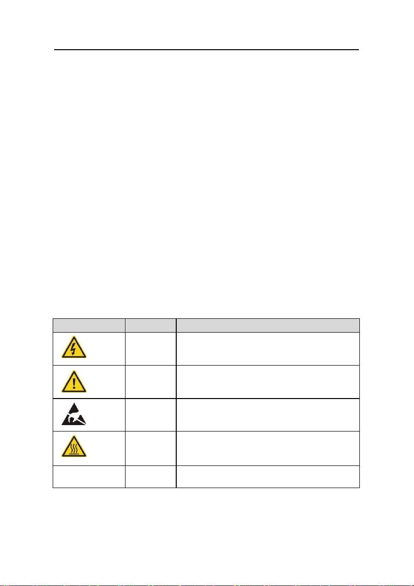
Symbols
Name
Instruction
Danger
Electrical
Danger
Serious physical injury or even death may occur if
not follow the
relative requirements
Warning
General
danger
Physical injury or damage to the devices may
occur if not follow the
relative requirements
Do not
Electrostatic
discharge
Damage to the PCBA board may occur if not
follow the relative
requirements
Hot sides
Hot sides
Sides of the device may become hot. Do not touch.
Note
Note
Physical hurt may occur if not follow
the relative requirements
Safety Precautions 1
1.1 What this chapter contains
Please read this manual carefully and follow all safety precautions before moving, installing,
operating and servicing the inverter. If ignored, physical injury or death may occur, ordamage
may occur to the devices.
If any physical injury or death or damage to the devices occurs for ignoring to the safety
precautions in the manual, our company will not be responsible for any damages and we are
not legally bound in any manner.
1.2 Safety definition
Danger: Serious physical injury or even death may occur if not follow
relevant requirements
Warning: Physical injury or damage to the devices may occur if not follow
relevant requirements
Note: Physical hurt may occur if not follow relevant requirements
Qualified
electricians: People working on the device should take part in professional
electrical and safety training, receive the certification and befamiliar
with all steps and requirements of installing,
commissioning, operating and maintaining the device to avoid any
emergency.
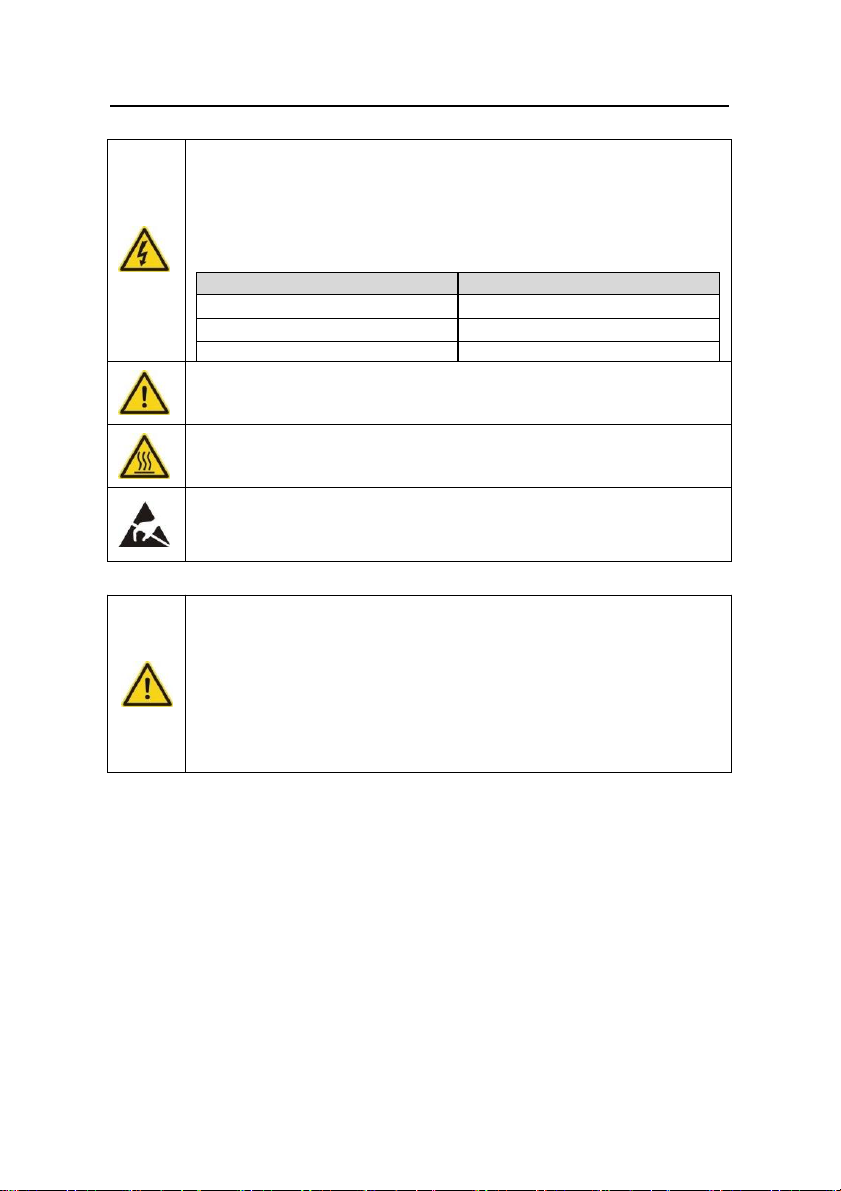
1.3 Warning symbols
Warnings caution you about conditions which can result in serious injury or death and/or
damage to the equipment, and advice on how to avoid the danger. Following warning
symbols are used in this manual:
Safety precautions
1.4 Safety guidelines
Only qualified electricians are allowed to operate on the inverter.
Do not carry out any wiring and inspection or changing components when the
power supply is applied. Ensure all input power supply is disconnected
before wiring and checking and always wait for at least the time designated on
the inverter or until the DC bus voltage is less than 36V. Below is the table of the
waiting time:
Inverter model
Minimum waiting time
380V 1.5kW-110kW
5minutes
380V 132 kW-315 kW
15minutes
380V above 350 kW
25 minutes
Do not refit the inverter unauthorized; otherwise fire, electric shock or other
injury may occur.
The base of the heat sink may become hot during running. Do not touch to
avoid hurt.
The electricalparts and componentsinsidethe inverter are electrostatic. Take
measurements to avoid electrostatic dischargeduring relevant operation.
1.4.1 Delivery and installation
Please install the inverter on fire-retardant material and keep the inverter
away from combustible
m
aterials.
Connect the braking optional parts (braking resistors, braking units or
feedback units) according to the wiring diagram.
Do not operate on the inverter if there is any damage or components loss to
the inverter.
Do not touch the inverter with wet items or body, otherwise electric shock
may occur.
Note:
Select appropriate moving and installing tools to ensure a safe and normal running of
the inverter and avoid physical injury or death. For physical safety, the erector should
take some mechanical protective measurements, such as wearing exposure shoes and
working uniforms.
Ensure to avoid physical shock or vibration during delivery and installation.
Do not carry the inverterby its cover. The cover may fall off.
Install away from children and other public places.
The inverter cannot meet the requirements of low voltage protection in IEC61800-5-
1 if the sea level of installation site is above 2000m.
Please use the inverter on appropriate condition (See chapter Installation
Environment).
Don't allow screws, cables and other conductive items to fall inside the inverter.
The leakage current of the inverter may be above 3.5mA during operation. Ground
2

3
Safety precautions
with proper techniques and ensure the grounding resistor is less than 10Ω. The
conductivity of PE grounding conductor is the same as that of the phase conductor
(with the same cross sectional area).
R, S and T are the input terminals of the power supply, while U, V and W are the motor
terminals. Please connect the input power cables and motor cables with proper
techniques; otherwise the damage to the inverter may occur.
1.4.2 Commission and running
Disconnect all power supplies applied to the inverter before the terminal wiring
and wait for at least the designated
tim
e after disconnecting the power supply.
High voltage is present inside the inverter during running. Do not carry out
any operation except for the keypad setting.
The inverter may start up by itself when P01.21=1. Do not get close to
the inverter and motor.
The inverter can not be used as “Emergency-stopdevice”.
Theinverter cannot be used to break themotor suddenly. A mechanicalbraking
device should be provided.
Note:
Do not switch on or off the input power supply of the inverter frequently.
For inverters that have been stored for a long time, check and fix the capacitance and try
to run it again before utilization (see Maintenance and Hardware Fault Diagnose).
Cover the front board before running, otherwise electric shock
m
ay occur.
1.4.3 Maintenance and replacement of components
Only qualified electricians are allowed to perform the maintenance,
inspection, and components replacement of the inverter.
Disconnect all power supplies to the inverter before the terminal wiring.
Wait for at least the time designated on the inverter after disconnection.
Takemeasuresto avoid screws, cables and other conductive
m
atters to fall into
the inverter during maintenanceand component replacement.
Note:
Please select proper torque to tighten screws.
Keep the inverter, parts and components away from combustible materials during
maintenance and component replacement.
Do not carry out any isolation and pressure test on the inverter and do not measure
the control circuit of the inverter by megameter.
Carry out a sound anti-electrostatic protection to the inverter and its internal
components during maintenance and component replacement.
1.4.4 What to do after scrapping
There are heavy metals in the inverter. Deal with it as industrial effluent.

4
Quick Start-up 2
2.1 What this chapter contains
This chapter mainly describes the basic guidelines during the installation and commission
procedures on the inverter, which you may follow to install and commission the inverter
quickly.
2.2 Unpacking inspection
Check as followings after receiving products:
1. Check that there are no damage and humidification to the package. If not, please
contact
with local agents.
2. Check the information on the type designation label on the outside of the package to
verify that the drive is of the correct type. If not, please contact with local dealers.
3. Check that there are no signs of water in the package and no signs of damage or breach
to the inverter. If not, please contact with local dealers.
4. Check the information on the type designation label on the outside of the package to
verify that the name plate is of the correct type. If not, please contact with local dealers.
5. Check to ensurethe accessories (including user’s manual, control keypad and extension
card) inside the device is complete. If not, please contact with local dealers.
2.3 Application confirmation
Check the machine before beginning to use the inverter:
1. Check the load type to verify that there is no overload of the inverter during work and
check that whether the drive needs to modify the power degree.
2. Check that the actual current of the motor is less than the rated current of the inverter.
3. Check that the control accuracy of the load is the same of the inverter.
4. Check that the incoming supply voltage is correspondent to the rated voltage of the
inverter.
2.4 Environment
Check as followings before the actual installation and usage:
1. Check that the ambient temperature of the inverter is below 40℃. If exceeds, derate 3%
for every additional 1℃.
temperature is above 50℃. Additionally, the inverter can not be used if the ambient
Note: for the cabinet inverter, the ambient temperature
m
eans the air temperature inside
the cabinet.
2. Check that the ambient temperature of the inverter in actual usage is above -10℃. If not,
add heating facilities.
Note: for the cabinet inverter, the ambient temperature means the air temperature inside
the cabinet.

55
3. Check that the altitude of the actual usage site is below 1000m. If exceeds, derate1% for
every additional 100m.
. Check that the humidity of the actual usage site is below 90% and condensation is not
allowed. If not, add additional protection inverters.
5. Check that the actual usage site is away from direct sunlight and foreign objects can not
enter the inverter. If not, add additional protective measures.
6. Check that there is no conductive dust or flammable gas in the actual usage site. If not,
add additional protection to inverters.
2.5 Installation confirmation
Check as followings after the installation:
1. Check that the input and output cables meet the need of actual load.
2. Check that the accessories of the inverter are correctly and properly installed. The
installation cables should meet the needs of every component (including reactors, input
filters, output reactors, output filters, DC reactors, braking units and braking resistors).
3. Check that the inverter is installed on non-flammable materials and the calorific
accessories (reactors and braking resistors) are away from flammable
m
aterials.
4. Check that all control cables and power cables are run separately and the
routation complies with EMC requirement.
5. Check that all grounding systems are properly grounded according to the requirements
of the inverter.
6. Check that the free space during installation is sufficient according to the instructions in
user’s manual.
7. Check that the installation conforms to the instructions in user’s manual. The drive must
be installed in an upright position.
8. Check that the external connection terminals are tightly fastened and the torque is
appropriate.
9. Check that there are no screws, cables and other conductive items left in the inverter. If
not, get them out.
2.6 Basic commission
Completethe basic commissioning as followings before actual utilization:
1. Select the motor type, set correct motor parameters and select control mode of the
inverter according to the actual motor parameters.
2. Autotune. If possible, de-coupled from the motor load to start dynamic autotune. Or if not,
static autotuneis available.
3. Adjust theACC/DEC time according to the actual running of the load.
4. Commission the device via jogging and check that the rotation direction is as required. If
not, change the rotation direction by changing the wiring of motor.
5. Set all control parameters and then operate.
Quick Start-up
66
Product Overview 3
3.1 What this chapter contains
The chapter briefly describes the operation principle, product characteristics, layout, name
plate and type designation information.
3.2 Basic principles
TETA MA610 series inverters are wall, flange and mountable devices for controlling
asynchronous AC inductance motors.
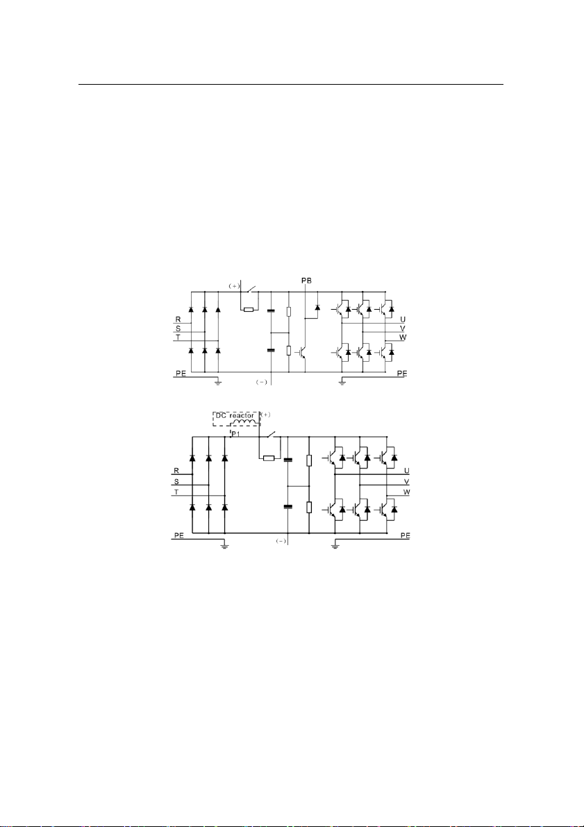
The diagram below shows the main circuit diagram of the inverter. The rectifier converts
three-phase AC voltage to DC voltage. The capacitor bank of the intermediate circuit
stabilizes the DC voltage. The converter transforms the DC voltage back to AC voltage for
the AC motor. The brake pipe connects the external braking resistor to the intermediate DC
circuit to consume the feedback energy when the voltage in the circuit exceeds its maximum
limit.
Diagram 3-1 The main circuit diagram (≤30kW )
Note:
Diagram 3-2 The main circuit diagram (≥37kW )
1. The inverter above 37kW (including 37kW) supports external DC reactor which is an
optional part. Before connecting, it is necessary to remove the copper row between P1 and
(+).
2. The inverters (≤30kW ) havestandard embedded braking units and the braking resistor
is optional.
3. The inverters (≥37kW ) can be installed with optional braking units and the braking
unit and resistor are optional.

77
Product Overview
3.3 Product specification
Function
Specification
Input
Input voltage (V)
AC 3PH 220V(-15%)~240V(+10%)
AC 3PH 380V(-15%)~440V(+10%)
AC 3PH 520V(-15%)~690V(+10%)
Input current (A)
Refer to the rated value
Input frequency (Hz)
50Hz or 60Hz
Allowed range: 47~63Hz
Output
Output voltage (V)
0~Input voltage
Output current (A)
Refer to the rated value
Output power (kW)
Refer to the rated value
Output frequency (Hz)
0~400Hz
Technical
control
feature
Control mode
SVPW M, SVC
Motor type
Asynchronous motor
Speed ratio
Asynchronous motor 1:100 (SVC)
Speed control
accuracy
±0.2% (sensorless vector control)
Speed fluctuation
± 0.3%(sensorlessvector control)
Torque response
<20ms(sensorless vector control)
Torque control
accuracy
10%(sensorless vector control)
Starting torque
Asynchronous motor: 0.5Hz/150% (SVC)
Overload capability
G type:
150% of rated current: 1 minute
180% of rated current: 10 seconds
200% of rated current: 1 second
Running
control
feature
Frequency setting
Digital setting, analog setting, pulse frequency
setting, multi-step speed running setting, simple
PLC setting, PID setting, MODBUS communication
setting.
Shift between the set combination and set channel.
Auto voltage
adjustment
Keep a stable voltage automatically when the grid
voltagetransients
Fault protection
Provide over 30 fault protection functions:
overcurrent, overvoltage, undervoltage, overheating,
phase loss and overload, etc.
Speed tracking
Restart the rotating motor smoothly
Note: This function is available for the inverters of
4kW and above 4kW.
Peripheral
Terminal analog input
≤20mV

88
Function
Specification
interface
resolution
Terminal switch input
resolution
≤2ms
Analog input
1 channels ( AI2) 0~10V/0~20mA and 1 channel
(AI3) -10~10V
Analog output
2 channels (AO1, AO2) 0~10V /0~20mA
Digital input
8 channels common input, the Max. frequency:
1kHz, internal impedance: 3.3kΩ;
1 channel high speed input, the Max. frequency:
50kHz
Digital output
1 channel high speed pulse output, the Max.
frequency: 50kHz;
1 channel Y terminal open collector pole output
Relay output
2 channels programmablerelay output
RO1A NO, RO1B NC, RO1C common terminal
RO2A NO, RO2B NC, RO2C common terminal
Contactor capability: 3A/AC250V,1A/DC30V
Others
Mountable method
Wall, flange and floor mountable
Temperature of the
running environment
-10~50℃, derate above 40℃
Ingress protection
IP20
Cooling
Air-cooling
Braking unit
Built-in braking unit for inverters below 30kW
(including 30kW )
External braking unit for others
EMC filter
Built-in C3 filter: meet the degree requirement of
IEC61800-3 C3
External optional filter:meet the degree requirement
of IEC61800-3 C2
3.4 Name plate
Fig 3-3 Name plate
Note: This is the example of the name plate for the standard products, and CE\TUV\IP20 will
be marked according to the actual situations.
Product Overview

99
3.5 Type designation key
The type designation contains information on the inverter. The user can find the type
designation on the type designation label attached to the inverter or the simple name plate.
Fig 3-4 Product
type
Key
Instructions
A
MA610: abbreviation of TETA MA610
B,
D
3-digit code: output power. “R”means the decimal point;
”011”:11kW
;
“015”:15kW
C,
E
C
G:Constant torque load
E
P:Variable torque load
F
Input voltage degree:
2: AC 3PH 220V(-15%)~240V(+10%)
4: AC 3PH 380V(-15%)~ 440V(+10%)
6: AC 3PH 520V(-15%)~690V(+10%)
3.6 Rated specifications
Model
Constant torque
Variable torque
Output
power
(kW)
Input
current
(A)
Output
current
(A)
Output
power
(kW)
Input
current
(A)
Output
current
(A)
MA610-0R7G-4
0.75
3.4
2.5
MA610-1R5G-4
1.5
5.0
3.7
MA610-2R2G-4
2.2
5.8
5
MA610-004G/5R5P-4
4
13.5
9.5
5.5
19.5
14
MA610-5R5G/7R5P-4
5.5
19.5
14
7.5
25
18.5
MA610-7R5G/011P-4
7.5
25
18.5
11
32
25
MA610-011G/015P-4
11
32
25
15
40
32
MA610-015G/018P-4
15
40
32
18.5
47
38
MA610-018G/022P-4
18.5
47
38
22
56
45
MA610-022G/030P-4
22
56
45
30
70
60
MA610-030G/037P-4
30
70
60
37
80
75
MA610-037G/045P-4
37
80
75
45
94
92
MA610-045G/055P-4
45
94
92
55
128
115
MA610-055G/075P-4
55
128
115
75
160
150
MA610-075G/090P-4
75
160
150
90
190
180
MA610-090G/110P-4
90
190
180
110
225
215
MA610-110G/132P-4
110
225
215
132
265
260
Product Overview
10
Note:
1. The input current of 1.5~315kW inverters is measured when the input voltageis 380V and
no DC reactor and input/output reactor.
2. The input current of 350~500kW inverters is measured when the input voltage is 380V
and the circuit is with input reactor.
3. The rated output current is defined as the output current when the output voltageis 380V.
4. In the allowable voltage range, the output power and current can not exceed the rated
output power and current in any situation.
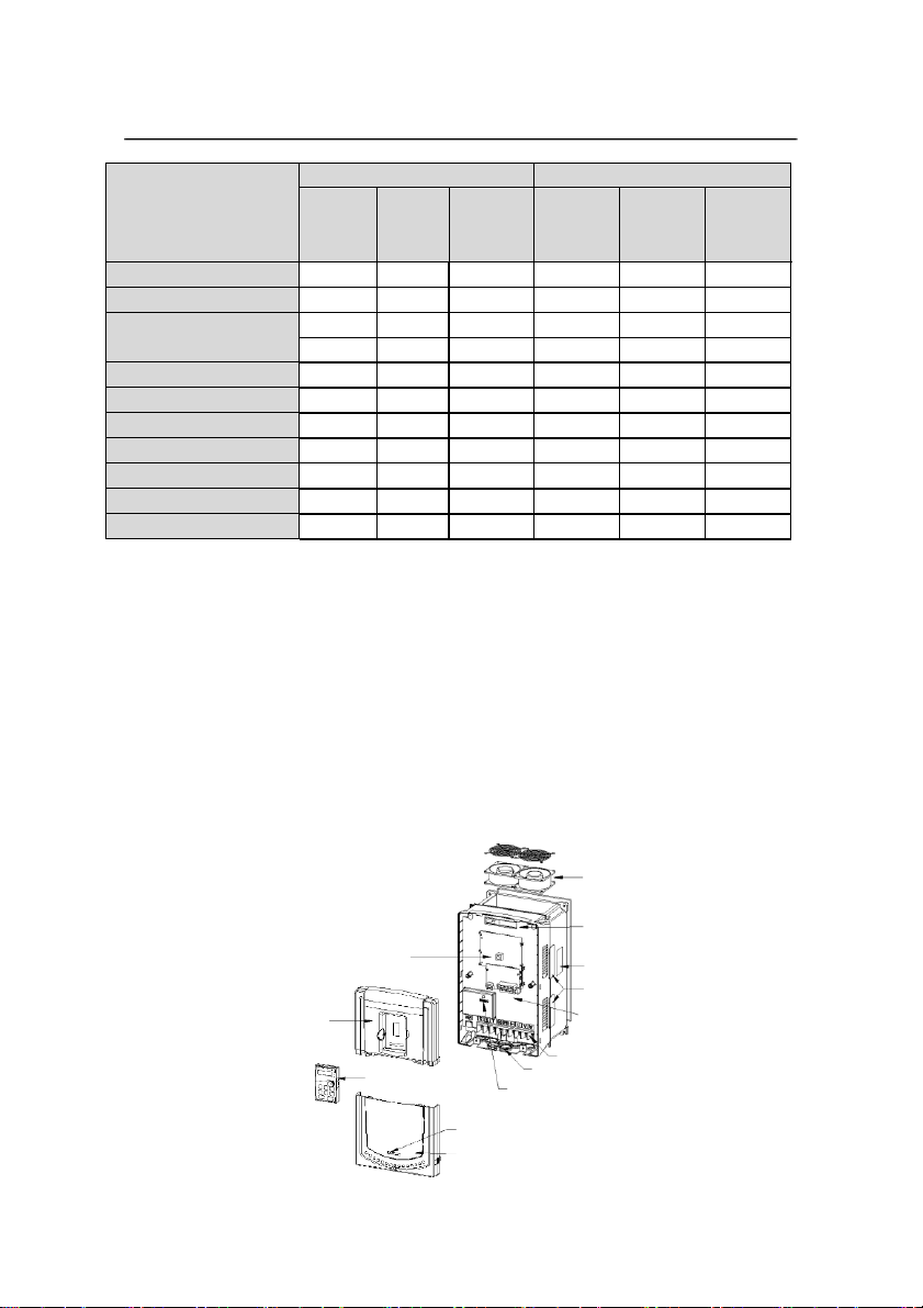
3.7 Structure diagram
Below is the layout figure of the inverter (take the inverter of 30kW as the example).
4
5
1 6
7
2 8
9
3 10
11
12
13
Fig 3-5 Product structure diagram
Model
Constant torque
Variable torque
Output
power
(kW)
Input
current
(A)
Output
current
(A)
Output
power
(kW)
Input
current
(A)
Output
current
(A)
MA610-132G/160P-4
132
265
260
160
310
305
MA610-160G/185P-4
160
310
305
185
345
340
MA610-185G/200P-4
185
345
340
200
385
380
MA610-200G/220P-4
200
385
380
220
430
425
MA610-220G/250P-4
220
430
425
250
485
480
MA610-250G/280P-4
250
485
480
280
545
530
MA610-280G/315P-4
280
545
530
315
610
600
MA610-315G/350P-4
315
610
600
350
625
650
MA610-350G/400P-4
350
625
650
400
715
720
MA610-400G-4
400
715
720
MA610-500G-4
500
890
860
Product Overview

Product Overview
11
Serial
No.
Name
Illustration
1
Keypad port
Connect the keypad
2
Upper cover
Protect the internal parts and components
3
Keypad
See Keypad Operation Procedure for detailed
information
4
Cooling fan
See Maintenance and Hardware Fault Diagnose for
detailed
inform
ation
5
Wires port
Connect to the control board and the drive board
6
Name plate
See Product Overview for detailed
inform
ation
7
Side cover
Optional part. The side cover will increase the
protective degree of the inverter. The internal
temperature of the inverter will increase, too, so it is
necessary to derate the inverter at the same time
8
Control terminals
See Electric Installation for detailed information
9
Main circuit terminals
See Electric Installation for detailed information
10
Main circuit cable entry
Fix the main circuit cable
11
POWER light
Power indicator
12
Simplename plate
See Product Overview for detailed information
13
Lower cover
Protect the internal parts and components

12
Environment
Conditions
Installation site
Indoor
Environment
temperature
-10~+50℃
If the ambient temperature of the inverter is above 40℃, derate 3%
for every additional 1℃.
It is not recommendedto use the inverter if the ambient
temperature is above 50℃.
In order to improve the reliability of the device, do not use the
inverter if the ambient temperature changes frequently.
Please provide cooling fan or air conditioner to control the internal
ambient temperature below the required one if the inverter is used
in a close space such as in the control cabinet.
When the temperature is too low, if the inverter needs to restart to
run after a long stop, it is necessaryto provide an external heating
device to increase the internal temperature, otherwise damage
to
the devices may occur.
Humidity
RH≤90%
No condensation is allowed.
Installation Guidelines 4
4.1 What this chapter contains
The chapter describes the mechanical installation and electric installation.
Only qualified electricians are allowed to carry out what described in this
chapter. Please operate as the instructions in Safety Precautions. Ignoring
these
m
ay cause physical injury or death or
dam
age to the devices.
Ensure the power supply of the inverter is disconnected during the operation.
Wait for at least the time designated until the POWER indicator is off after the
disconnection if the power supply is applied. It is recommended to use the
multimeter to monitor that the DC bus voltage of the drive is under 36V.
The installation and design of the inverter should be complied with the
requirement of the local laws and regulations in the installation site. If the
installation infringes the requirement, our company will exempt from any
responsibility. Additionally, if users do not comply with the suggestion, some
damagebeyond the assured maintenancerange may occur.
4.2 Mechanical installation
4.2.1 Installation environment
The installation environment is important for a full performance and long-term
stable functions of the inverter. Check the installation environment as followings:
13
Note:
TETA MA610 series inverters should be installed in a clean and ventilated environment
according to enclosure classification.
Cooling air must be clean, free from corrosive materials and electrically conductive dust.
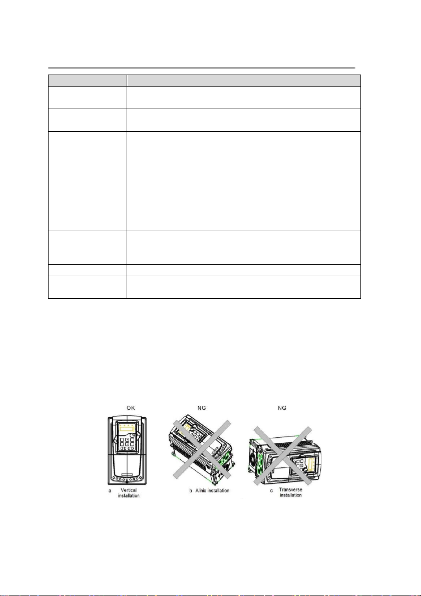
4.2.2 Installation direction
The inverter may be installed on the wall or in a cabinet.
The inverter must be installed in an upright position. Check the installation site according to
the requirements below. Refer to chapter Dimension Drawings in the appendix for
frame details.
Fig 4-1 Installation direction of the inverter
Environment
Conditions
The maximum relative humility should be equal to or less than
60% in corrosive air.
Storage
temperature
-30~+60℃
Running
environment
condition
The installation site of the inverter should:
keep away from the electromagnetic radiation source;
keep away from contaminative air, such as corrosive gas, oil mist
and flammablegas;
ensure foreign objects, such as metal power, dust, oil, water can
not enter into the inverter(do not install the inverter on the
flammable materials such as wood);
keep away from direct sunlight, oil mist, steam and vibration
environment.
Altitude
Below 1000m
If the sea level is above 1000m, please derate 1% for every
additional 100m.
Vibration
≤ 5.8m/s2(0.6g)
Installation direction
The inverter should be installed on an upright position to ensure
sufficient cooling effect.
Installation Guidelines

14
4.2.3 Installation manner
The inverter can be installed in two different ways, depending on the frame size:
a) Wall mounting (for the inverter≤315kW )
b) Flange mounting (for the inverter≤200kW ). Some need optional flange installation
board. c) Floor mounting (220kW ≤the inverter≤500kW ). Some need optional base.
Fig 4-2 Installationmanner
(1) Mark the hole location. The location of the holes is shown in the dimension drawings in
the appendix.
(2) Fix the screws or bolts to the marked locations.
(3) Position the drive onto the wall.
(4) Tighten the screws in the wall securely.
Note:
1. The flange installation bracket is needed in the flange installation of 1.5~30kW inverters,
which the flange installation of 37~200kW inverters does not need the installation bracket.
2. 220~315kW inverters need optional base in the floor installation.
4.2.4 Multiple installations
Parallel installation
Note:
Fig 4-3 Parallel installation
Before installing the different sizes inverters, please align their top position for the
convenience of later maintenance.
The minimum space of B, D and C is 100mm.
Installation Guidelines
15
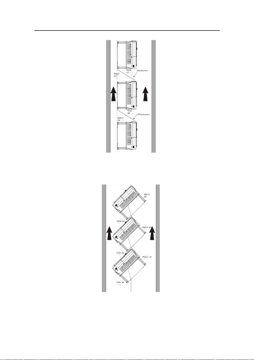
4.2.5 Vertical installation
Fig 4-4 Vertical installation
Note:
W
indscreen should be added in vertical installation for avoiding mutual impact and
insufficient cooling.
4.2.6 Tilt installation
Fig 4-5 Tilt installation
Note: Ensure the separation of the wind input and output channels in tilt installation for
avoiding mutual impact.
Installation Guidelines

16
4.3 Standard wiring
4.3.1 Wiring diagram of main circuit
Note: Fig4-6Wringdiagram of maincircuit
Thefuse, DC reactor, braking unit, braking resistor, input reactor, input filter, output
reactor, output filter are optional parts. Please refer to Peripheral Optional Parts for
detailed information.
A1 and A2 are optional parts.
P1 and (+) are short circuited in factory, if need to connect with the DC rector, please
remove the contact tag between P1 and (+).
4.3.2 Terminals figure of main circuit
Fig 4-7 0.75~5.5 kW terminals of main circuit
Fig 4-8 7.5~15kW terminals of main circuit
Installation Guidelines
This manual suits for next models
28
Table of contents
Other TETA Electric Inverter manuals


