Electway Sununo-TL1-5K User manual

P
Preface
Guangzhou Electway
E lectric Co., Ltd.
GREEN TECHNIC GREEN FUTURE
Thank you for choosing our solar inverter. We are happy to provide
you with first-class products and quality service.
The manual includes installation, operation, maintenance,
troubleshooting, and safety notice. As long as you follow the
instruction of this manual, you will get the professional guidance
and our wholehearted service.
Customer-orientation is our forever commitment. We hope this
“User Manual” become your good helper in solar power generation.
This manual subjects to change at regular intervals according to
customer's feedback.
Please check the latest version at www.saj-solar.com

C
Contents
User Manual
...............................................................................1
............................................................................1
.......................................................................................1
........................................................................................2
................................................................................................2
........................................................................2
................................................................................3
................................................5
.................................................................................6
..............................................................................................6
..........................................................................6
............................................................................................8
................................................................................................12
..................................................................................12
..........................................................................13
............................................................................15
...............................................................................................15
..................................................................................................15
.......................................................................16
...............................................................................17
.........................................................................17
...................................................................................20
.......................................................................................21
............................................................................21
................................................................................21
........................................................................22
1. Notes on
1.1 Scope of Validation
1.2 Symbols Used
1.3 Target Group
2. Preparation
2.1 System Demonstration
2.2 Safety Instructions
2.3 Explanations of Symbols on Inverter
3. Product Information
3.1 Overview
3.2 Major Characteristics
3.3 Datasheet
4. Unpacking
4.1 Assembly Parts
4.2 Product Appearance
4.3 Further Information
5. Installation
5.1 Safety
5.2 Mounting Instructions
5.3 Safety Clearance
5.4 Mounting Procedure
5.5 Check Varistors
5.6 Maintenance
5.7 Module Technology
5.8 Pollution Degree
5.9 Overvoltage Category
This Manual 6. Electrical Connection
6 1 Safety
6.2 Overview of Connection Area
6.3 AC Side Connection
6.4 DC Side Connection
6.5 DC Side Disconnection
6.6 Communication and Monitoring Setting
7. LCD Operation
7.1 LCD Display
7.2 Operation Method
7.2.1 Button Function
7.2.2 Run-Information
7.2.3 Fault-Record
7.2.4 History Fault
7.2.5 Set Parameters
7.2.6 Check The Inverter Information
8. Recycling and Disposal
9. Troubleshooting
10. Guaranty Service
11. Contact Us
Abbreviation
.
6. 6. 1 Ethernet Setting
6. 6. 2 RS485 Setting
.............................................................................22
..................................................................................................22
...........................................................23
..........................................................................24
..........................................................................28
......................................................................33
...........................................33
...............................................................................34
...................................................................................36
.........................................................................................40
......................................................................................40
...............................................................................40
.............................................................................40
............................................................................43
...................................................................................44
...................................................................................45
................................................................................45
....................................................46
...........................................................................47
......................................................................................47
...................................................................................52
...........................................................................................52
.................................................................................................53
ADD:2OOM#./'UAN9U2OAD4ANG$ONG4IAN(E$ISTRICT'UANG:HOU'UANG$ONG#HINA
Quotation Sheet NO.:20120611
www.lowcarbon-idea.com [email protected]
1. NOTES ON THIS MANUAL
This discribes instructions and detailed procedures for installing,
operating, maintaining, and troubleshooting of the following SAJ grid-tie
inverters:
Please keep this manual all time available in case of emergency.
User Manual
1.2 SYMBOLS USED
2. PREPARATION
DANGER
DANGER indicates a hazardous situation which, if not
avoided, will result in death or serious injury.
CAUTION indicates a hazardous condition which, if not
avoided, can result in minor or moderate injury.
CAUTION
NOTICE indicates a situation that can result in potential
damage, if not avoided.
NOTICE
WARNING
avoided, can result in death or serious injury or moderate
injury.
WARNING indicates a hazardous situation which, if not
1 2
Sununo– TL5K
Sununo– TL2K,Sununo– TL1.5K, Sununo– TL3KB, Sununo– TL4KB,
Sununo– TL3KA, Sununo– TL4KA, Sununo– TL4.4K,
1.3 TARGET GROUP
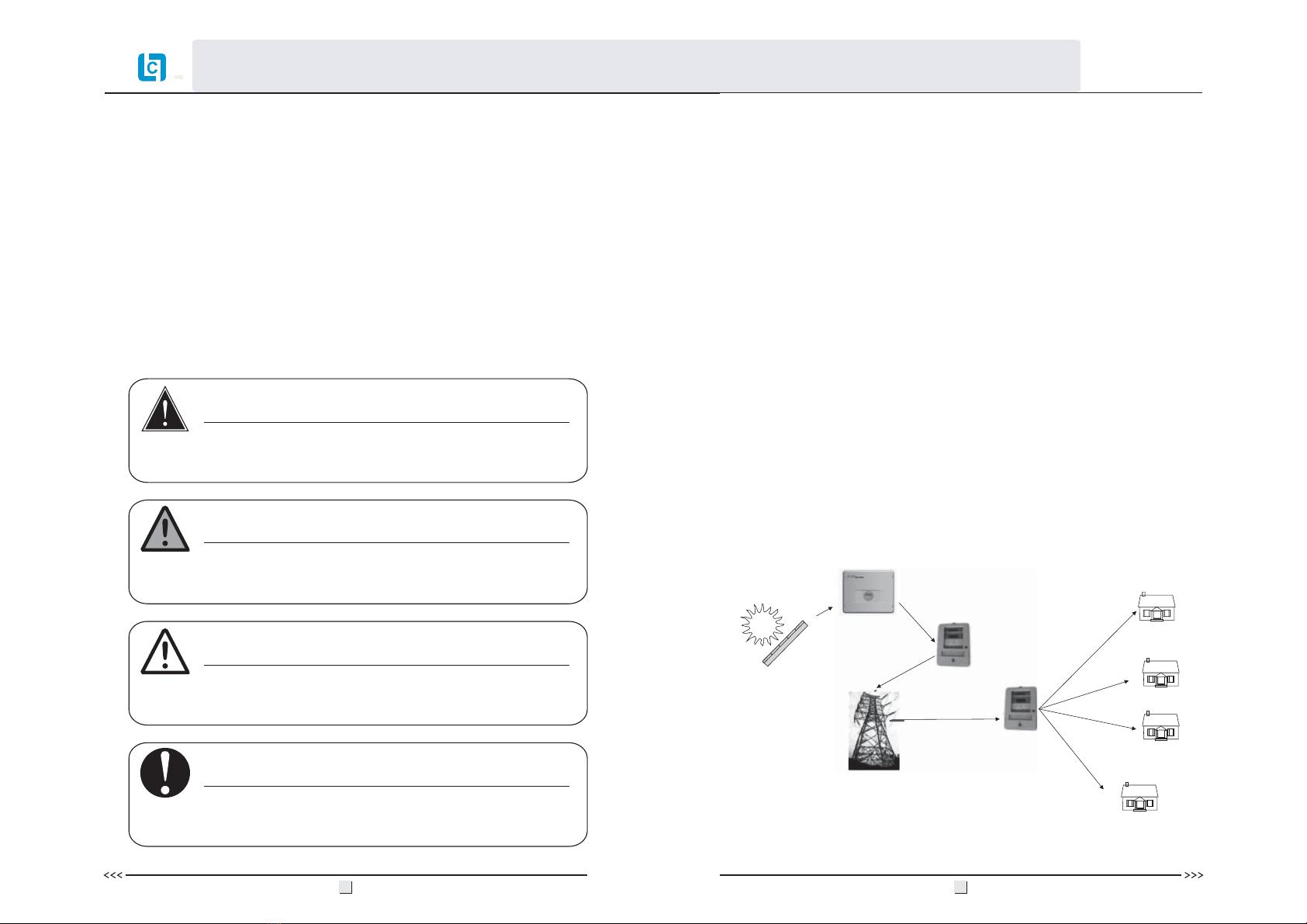
Solar energy generation systems, based on photovoltaic modules, nowadays
represent the most suitable solution to reduce the energy consumption
produced by oil and gas.
The solar inverter is a key device in a solar energy system. It performs the
conversion of the variable DC output of the PV modules into a clean sinusoidal
50Hz/60Hz AC current that is then directly applied to the commercial
electrical grid or to a local grid electrical network.
Typically, solar inverter includes communication function to monitor
operating condition, firmware to update and control the grid connection.
Depending on the grid infrastructure, cabled (RS-485, CAN, Power Line
Communication, Ethernet) or cableless (Bluetooth, ZigBee/IEEE802.15.4)
networking options can be used.
2.1 SYSTEM DEMONSTRATION
Figure 2.1
Solar
Panels
Purchase
Solar
inverter
Grid
Sell
Only qualified electricians who have read and fully understood all safety
regulation contained in this manual can install, maintain and repair the
inverter. Operators must be aware of the high-voltage device.
1.1 SCOPE OF VALIDATION
User Manual
ADD:2OOM#./'UAN9U2OAD4ANG$ONG4IAN(E$ISTRICT'UANG:HOU'UANG$ONG#HINA
Quotation Sheet NO.:20120611
www.lowcarbon-idea.com [email protected]

2.2 SAFETY INSTRUCTIONS
3 4
DANGER
·
·
·
·o not
·o not
·
DANGER due to electrical shock and high voltage
Do not touch the operating component of the inverter, it
might result in burning or death.
To prevent risk of electric shock during installation and
maintenance, please make sure that all AC and DC
terminals are plugged out.
D touch the surface of the inverter while the
housing is wet, it might lead to electrical shock.
D stay close to the instruments while there are
severe weather conditions including storm, lighting, etc.
Before opening the housing, the SAJ inverter must be
disconnected from the grid and PV generator; you must
wait at least five minutes to let the energy storage
capacitors fully discharged after disconnecting from
power source.
WARNING
·
·
deny
·must only be operated
·
properties
The installation,service ,recycling and disposal of
the inverters must be performed by qualified personnel
only in compliance with national and local standards and
regulations.
Any unauthorized actions including modification of
product functionality of any form may cause lethal
hazard to the operator, third parties, the units or their
property. SAJ is not responsible for the loss and
these warranty claims.
The SAJ inverter with PV
generator. Do not connect any other source of energy to
the SAJ inverter.
Be sure that the PV generator and inverter connect to
the ground in order to protect and persons.
NOTICE
·
Public utility only.
·
;
The PV inverter is designed to feed AC power directly
to the public utility power grid do not connect AC
output of the device to any private AC equipment.
CAUTION
·
·
·
·
The PV inverter will become hot during operation.
Please don’t touch the heat sink or peripheral surface
during or shortly after operation.
Risk of damage due to improper modifications.
Never modify or manipulate the inverter or other
components of the system.
For radiation prevention, do not stay closer than 20cm
to the inverter for any length of time.
User Manual
ADD:2OOM#./'UAN9U2OAD4ANG$ONG4IAN(E$ISTRICT'UANG:HOU'UANG$ONG#HINA
Quotation Sheet NO.:20120611
www.lowcarbon-idea.com [email protected]

2.3 EXPLANATIONS OF SYMBOLS ON INVERTER 3.PRODUCT INFORMATION
3.1 OVERVIEW
Industrial design Reduced Heat Sink
3.2 MAJOR CHARACTERISTICS
SAJ grid - tie solar inverter has following characteristics which make SAJ
grid - tie solar inverter “High Efficiency, High Reliability, High Cost -
Effective Ratio”.
Figure 3.1
5 6
Sununo-TL1.5K/2K
Sununo-TL3KB/4KB
Sununo-TL 3KA/4KA/4.4K/5K
Symbol Description
Dangerous electrical voltage
This device is directly connected to public grid, thus all work to
the inverter shall only be carried out by qualified personnel.
DANGER to life due to high electrical voltage!
There might be residual currents in inverter because of large
capacitors. Wait 5 MINUTES before you remove the front lid.
NOTICE, danger!
This is directly connected with electricity generators and public
grid.
Danger of hot surface
The components inside the inverter will release a lot of heat
during operation. Do not touch metal plate housing during
operating.
An error has occurred
Please go to Chapter 9 “Troubleshooting” to remedy the error.
This device SHALL NOT be disposed of in residential waste
Please go to Chapter 8 “Recycling and Disposal” for proper
treatments.
Without Transformer
This inverter does not use transformer for the isolation function.
Certified safety
The inverter complies with the requirement of the Equipment
and Product Safety Act in Europe.
CE Mark
Equipment with the CE mark fulfills the basic requirements of
the Guideline Governing Low-Voltage and Electro-magnetic
Compatibility.
No unauthorized perforations or modifications
Any unauthorized perforations or modifications are strictly
forbidden, if any defect or damage (device/person) is occurred,
SAJ shall not take any responsibility for it.
ATTENTION!
Risk of electric shock! Only
authorized personnel are
allowed to do disassembly,
modification or maintenance.
Any resulting defect or
damage (device/person) is not
covered by SAJ guaranty.
SAA Mark
The inverter complies with the requirement of Equipment
and Product Safety Act in Australia.
User Manual
ADD:2OOM#./'UAN9U2OAD4ANG$ONG4IAN(E$ISTRICT'UANG:HOU'UANG$ONG#HINA
Quotation Sheet NO.:20120611
www.lowcarbon-idea.com [email protected]

7
• High input voltage, can be connected with more PV panels
• TWO MPP trackers, wide MPPT voltage range fits in different locations or
various weather conditions
• High MPP tracking accuracy, catch most of electricity from panels
• Transformerless design
• PC remote control, multi communication interface (Ethernet, RS485, etc.)
• Multi language display
• Easy LCD operation
• DC switch (optional)
• High-grade power component
• Small size, light weight, easy installation
Besides, following protection methods are integrated in SAJ grid - tie solar
inverter:
• Internal overvoltage protection
• DC insulation monitoring
• DC side varistor
• Ground fault protection
• Grid monitoring
• Ground fault current monitoring
• Anti-islanding protection
3.3 DATASHEET
Sununo-TL2K
Type
Input DC()
Sununo-TL 1.5K/2K
Max. DC Power [W]
Max. DC Voltage [V]
MPPT Voltage Range [V]
MPPT Voltage Range[V](Full Load)
Maximum operating PV input current [A]
DC Nominal Voltage [V]
Start Voltage [V]
Min. DC Voltage [V]
Max. DC Current[A]
Number of DC Connection Sets
Number of MPP Trackers
DC Switch
1
1
Optional
480
120-384
360
150
100
Output (AC)
Rated AC Power [W]
Max. AC Power [W]
Rated AC Current [A]
Max. AC Current [A]
Maximum Output Fault Current
Power Factor(cos )
AC Current Distortion (THD)
Consumption at Night [W]
Consumption at Standby [W]
φ>0.99(full load)
< 2%
<0.5
6
Efficiency
Max. Efficiency
Euro Efficiency (at 360Vdc)
MPPT Accuracy
Protection
Internal Overvoltage Protection
DC Insulation Monitoring
DC Side Varistors
Direct Current Monitoring
Ground Fault Current Monitoring
Grid Monitoring
AC Short Current Protection
Thermal Protection
Islanding Protection
Integrated
Integrated
Integrated
Integrated
Integrated
Integrated
Integrated
AFD
Interface
AC Connection
DC Connection
LCD Display
Display Language
Datalogger & Communication
Terminals
MC4/H4
LCD(16x2 Characters, Backlight) & LED(3 Lights)
Multi Language
2*RS485(Standard), Ethernet(Optional)
General Data
Isolation
Operating Temperature Range
Cooling Method
Ambient Humidity
Site Altitude above Sea Level
Noise Emission (dBA)
IP Protection
Mounting
Dimensions (WxHxD) [mm]
Weight [kg]
Standard Warranty (Year)
Safety Class Compliance
EMC Compliance
Grid Protection Compliance
Transformerless
-25°C to +60°C (45°C to 60°C with derating )
Natural Convection
0% to 98% Non-condensing
Up to 2000m
<40
IP65 (Indoor or Outdoor Installation)
Rear Panel
415*313*140
11
5 / 10 /15/20/25(Optional)
IEC62109-1/-2
EN61000-6-1:4, EN61000-3-2:3
According to VDE 0126-1-1, RD1663, ENEL Guide 2010, G83,C10/C11
According to VDE 0126-1-1, RD1663, ENEL Guide 2010, G83,C10/C11
Sununo-TL1.5K
1800
9.3
11.0
164-384
1500
1650
6.5
8.5
97.4%
96.7%
99.9%
219A/0.84ms
2300
10.6
12.0
190-384
2000
2000
8.7
11.0
97.4%
96.7%
99.9%
230A/0.94ms
220V, 230V, 240V/180V-280V
AC Nominal Voltage/Grid Voltage Range
[
V
]
Frequency Range 50Hz,60Hz/±5Hz
8
User Manual
ADD:2OOM#./'UAN9U2OAD4ANG$ONG4IAN(E$ISTRICT'UANG:HOU'UANG$ONG#HINA
Quotation Sheet NO.:20120611
www.lowcarbon-idea.com [email protected]

Sununo-TL3KB
Type
Input DC()
3400
Output (AC)
Rated AC Power [W]
Max. AC Power [W]
Rated AC Current [A]
Max. AC Current [A]
Maximum output Fault Current
Power Factor(cos )
AC Current Distortion (THD)
Consumption at Night [W]
Consumption at Standby [W]
φ
Sununo-TL3KB/4KB
550
125-440
360
150
100
Max. DC Power [W]
Max. DC Voltage [V]
MPPT Voltage Range [V]
MPPT Voltage Range[V](Full Load)
DC Nominal Voltage [V]
Start Voltage [V]
Min. DC Voltage [V]
Max. DC Current Input[A]
Number of DC Connection Sets
Number of MPP Trackers
DC Switch
17
2
1
Optional
3000
3300
13.0
15.0
Efficiency
Max. Efficiency
Euro Efficiency (at 360Vdc)
MPPT Accuracy
Protection
Internal Overvoltage Protection
DC Insulation Monitoring
DC Side Varistors
Direct Current Monitoring
Ground Fault Current Monitoring
Grid Monitoring
AC Short Current Protection
Thermal Protection
Islanding Protection
Interface
AC Connection
DC Connection
LCD Display
Display Language
Datalogger & Communication
Terminals
MC4/H4
LCD(16x2 Characters, Backlight) & LED(3 Lights)
Multi Language
2*RS485(Standard), Ethernet(Optional)
General Data
Isolation
Operating Temperature Range
Cooling Method
Ambient Humidity
Site Altitude above Sea Level
Noise Emission (dBA)
IP Protection
Mounting
Dimensions (WxHxD) [mm]
Weight [kg]
Standard Warranty (Year)
Safety Class Compliance
EMC Compliance
Grid Protection Compliance
Transformerless
-25°C to +60°C (45°C to 60°C with derating )
Natural Convection
0% to 98% Non-condensing
Up to 2000m
<40
IP65 (Indoor or Outdoor Installation)
Rear Panel
450*375*177
5 / 10 /15/20/25(Optional)
IEC62109-1/-2
EN61000-6-1:4, EN61000-3-2:3
Integrated
Integrated
Integrated
Integrated
Integrated
Integrated
Integrated
AFD
>0.99(full load)
< 2%
<0.2
6
97.7%
97.1%
99.9%
121A/0.25ms
According to VDE 0126-1-1, RD1663, ENEL Guide 2010, G83,C10/C11
Sununo-TL4KB
16 19
97.6%
97.0%
99.9%
20
4500
200-440 225-440
4000
4400
17.4
20.0
145A/0.51ms
Sununo-TL3KA Sununo-TL4KA
Type
Input DC()
3200 4200
Output (AC)
Rated AC Power [W]
Max. AC Power [W]
Rated AC Current [A]
Max. AC Current [A]
Maximum output Fault Current
Power Factor(cos )
AC Current Distortion (THD)
Consumption at Night [W]
Consumption at Standby [W]
φ
Efficiency
Max. Efficiency
Euro Efficiency (at 360Vdc)
MPPT Accuracy
Protection
Internal Overvoltage Protection
DC Insulation Monitoring
DC Side Varistors
Direct Current Monitoring
Ground Fault Current Monitoring
Grid Monitoring
AC Short Current Protection
Thermal Protection
Islanding Protection
Interface
AC Connection
DC Connection
LCD Display
Display Language
Datalogger & Communication
Terminals
MC4/H4
LCD(16x2 Characters, Backlight) & LED(3 Lights)
Multi Language
2*RS485(Standard), Ethernet(Optional)
General Data
Isolation
Operating Temperature Range
Cooling Method
Ambient Humidity
Site Altitude above Sea Level
Noise Emission (dBA)
IP Protection
Mounting
Dimensions (WxHxD) [mm]
Weight [kg]
Standard Warranty (Year)
Safety Class Compliance
EMC Compliance
Grid Protection Compliance
Transformerless
-25°C to +60°C (45°C to 60°C with derating )
Natural Convection
0% to 98% Non-condensing
Up to 2000m
<40
IP65 (Indoor or Outdoor Installation)
Rear Panel
525× 425 ×175
23
5 / 10 /15/20/25(Optional)
IEC62109-1/-2
EN61000-6-1:4, EN61000-3-2:3
Integrated
Integrated
Integrated
Integrated
Integrated
Integrated
Integrated
AFD
>0.99(full load)
< 2%
<0.2
6
97.6%
97.0%
99.9%
97.6%
97.0%
99.9%
Sununo-TL3KA/4KA
550
125-440
200-440
360
150
100
Max. DC Power [W]
Max. DC Voltage [V]
MPPT Voltage Range [V]
MPPT Voltage Range [V](Full Load)
DC Nominal Voltage [V]
Min. DC Voltage [V]
Max. DC Current Input/Per String [A]
Number of DC Connection Sets
Number of MPP Trackers
DC Switch
Start Voltage [V]
21A/15A16A/15A
2
2(can parallel)/3(optional)
Optional
3000
3000
13.0
15.0
4000
4000
17.4
20.0
254A / 10.7ms152A / 5.2ms
According to VDE 0126-1-1, RD1663, ENEL Guide 2010, G83,C10/C11
220V, 230V, 240V/180V-280V
50Hz,60Hz/±5Hz
220V, 230V, 240V/180V-280V
50Hz,60Hz/±5Hz
9
AC Nominal Voltage/Grid Voltage Range V
[]
Frequency Range
AC Nominal Voltage/Grid Voltage Range[V]
Frequency Range
According to VDE 0126-1-1, RD1663, ENEL Guide 2010, G83,C10/C11
According to VDE 0126-1-1, RD1663, ENEL Guide 2010, G83,C10/C11
10
User Manual
ADD:2OOM#./'UAN9U2OAD4ANG$ONG4IAN(E$ISTRICT'UANG:HOU'UANG$ONG#HINA
Quotation Sheet NO.:20120611
www.lowcarbon-idea.com [email protected]

12
Sununo-TL4.4K/5K
Sununo-TL4.4K Sununo-TL5K
Type
Input (DC)
4600 5200
22.3
360
150
100
Output (AC)
Rated AC Power [W]
Max. AC Power [W]
Rated AC Current [A]
Max. AC Current [A]
Maximum output Fault Current
Power Factor(cosφ)
AC Current Distortion (THD)
Consumption at Night [W]
Consumption at Standby [W]
Efficiency
Max. Efficiency
Euro Efficiency (at 360Vdc)
MPPT Accuracy
Protection
Internal Overvoltage Protection
DC Insulation Monitoring
DC Side Varistors
Direct Current Monitoring
Ground Fault Current Monitoring
Grid Monitoring
AC Short Current Protection
Thermal Protection
Islanding Protection
Interface
AC Connection
DC Connection
LCD Display
Display Language
Datalogger & Communication
Terminals
MC4/H4
LCD(16x2 Characters, Backlight) & LED(3 Lights)
Multi Language
2*RS485(Standard), Ethernet(Optional)
General Data
Isolation
Operating Temperature Range
Cooling Method
Ambient Humidity
Site Altitude above Sea Level
Noise Emission (dBA)
IP Protection
Mounting
Dimensions (WxHxD) [mm]
Weight [kg]
Standard Warranty (Year)
Safety Class Compliance
EMC Compliance
Grid Protection Compliance
Transformerless
-25°C to +60°C (45°C to 60°C with derating )
Natural Convection
0% to 98% Non-condensing
Up to 2000m
<40
IP65 (Indoor or Outdoor Installation)
Rear Panel
525× 425 ×190
26
5 / 10 /15/20/25(Optional)
IEC62109-1/-2
EN61000-6-1:4, EN61000-3-2:3
>0.99(full load)
< 2%
<0.5
6
Integrated
Integrated
Integrated
Integrated
Integrated
Integrated
Integrated
AFD
550
125-440
200-440
25.3
26A/16A
23A/16A
2
2 (can parallel)/3(optional)
Optional
Max. DC Power [W]
Max. DC Voltage [V]
MPPT Voltage Range [V]
MPPT Voltage Range [V](Full Load)
Maximum operating PV input current(A)
DC Nominal Voltage [V]
Min. DC Voltage [V]
Max. DC Current Input/Per String [A]
Number of DC Connection Sets
Number of MPP Trackers
DC Switch
Start Voltage [V]
4400
4400
19.1
22.0
5000
5000
21.7
25.0
97.6%
97.0%
99.9%
97.6%
97.0%
99.9%
500A / 5.8ms361A / 5.8ms
According to VDE 0126-1-1, RD1663, ENEL Guide 2010, G83,C10/C11
220V, 230V, 240V/180V-280V
50Hz,60Hz/±5Hz
AC Nominal Voltage/Grid Voltage Range[V]
Frequency Range
According to VDE 0126-1-1, RD1663, ENEL Guide 2010, G83,C10/C11
11
4. UNPACKING
4.1 ASSEMBLY PARTS
After you receive the SAJ grid-tie solar inverter, please check if there is any
damage on the carton. Also, please check the inside completeness and for any
visible external damage on the inverter or any accessories. Contact your dealer
if anything is damaged or missing.
ABCD
EFGH I
Object Description
Quantity
A
B
D
E
F
H
I
1
1
2
6
6
1
1
SAJ grid-tie solar inverter
Rear panel
RS485 connector(if attached)
M6×50 Expansion screw
Expansion tube
M4×12 Cylinder head screw and Lock washer
(Sununo-TL1K/1.5K/2K/2.5K/3KB/4KB)
M5×12 Cylinder head screw and Lock washer
(Sununo-TL3KA/4KA/4.4K/5K)
User manual, including installation guide
Warranty card
C
4
G
Figure 4.1
DC connector (for Sununo-TL1K//1.5K/2K)
DC connector (for Sununo-TL2.5K/3KB/4KB/3KA/4KA/4.4K/5K)
1 sets
2 sets
*: There are three input connection modes for Sununo-TL5K as following:
a) PV1&PV2 Max. DC current input/ Per string(A): 26A/16A
b) PV1&PV3 Max. DC current input/ Per string(A): 26A/16A
c) PV1&PV2 + Pv3 Max. DC current input/ Per string(A): 26A/16A
Note:
When the inverter leave from SAJ factory, the PV1 is independent, PV2 and PV3 are
installed in parallel. Users are not allowed to change the original connection modes.
User Manual
ADD:2OOM#./'UAN9U2OAD4ANG$ONG4IAN(E$ISTRICT'UANG:HOU'UANG$ONG#HINA
Quotation Sheet NO.:20120611
www.lowcarbon-idea.com [email protected]

4.2 PRODUCT APPEARANCE
Front:
Figure 4.2
Object
A
B
C
D
E
F
Description
LED yellow light – POWER
LED red light – FAULT
LED green light – RUN
▼/ESC
▲/ENT
13 14
ABCDE
F
Sununo-TL1.5K/2K/3KB/4KB
ABCDE
Sununo-TL3KA/4KA/4.4K/5K
Bottom:
Bottom:
Sununo-TL1.5K/2K
Sununo-TL 3KB/4KB
E
F
ABC
FD
ABCE
D
LCD screen for viewing the running data & recorded information, and
setting parameters.
F
User Manual
ADD:2OOM#./'UAN9U2OAD4ANG$ONG4IAN(E$ISTRICT'UANG:HOU'UANG$ONG#HINA
Quotation Sheet NO.:20120611
www.lowcarbon-idea.com [email protected]

·
·
·
·
SAJ grid - tie solar inverter is cooled by natural flow of air behind the
inverter.
SAJ grid - tie solar inverter is designed for installation both indoors and
outdoors.
Please only mount the inverter in the direction as illustrated above.
15 16
Bottom:
Figure 4.3
Object
A
B
D
E
F
C
Description
DC switch to turn off the inverter manually(optional)
DC input
Plug for connecting the RS485 communication module
Plug for connecting the communication module optional
AC output
Heat sink
Ethernet ( )
4.3 FURTHER INFORMATION
If you have any further questions concerning the type of accessories or
installation, please check our website www.saj-solar.com or contact our
service hotline.
5. INSTALLATION
5.1 SAFETY
Sununo-TL3KA/4KA/4.4K/5K
DANGER
·
·o not
·
DANGER to life due to potential fire or electricity
shock.
D install the inverter near any inflammable or
explosive items.
This inverter will be directly connected with HIGH
VOLTAGE power generation device; the installation
must be performed by qualified personnel only in
compliance with national and local standards and
regulations.
NOTICE
·
·exposed
·
NOTICE due to the inappropriate or the harmonized
installation environment may jeopardize the life span of
the inverter.
Installation directly under intensive sunshine
is not recommended.
The installation site must have good ventilation
condition.
Figure 5.1 Bad cooling
15
ABC
D
E
F
5.2 MOUNTING INSTRUCTIONS
User Manual
ADD:2OOM#./'UAN9U2OAD4ANG$ONG4IAN(E$ISTRICT'UANG:HOU'UANG$ONG#HINA
Quotation Sheet NO.:20120611
www.lowcarbon-idea.com [email protected]

Figure5.2
Direction
Above
Below
Side
Front
Minimum Clearance
30 cm
50 cm
30 cm
5 cm
Figure 5.3
17 18
·
·
·
·
·
·
·Installing the inverter under strong sunshine is not recommended; the excess
heating might lead to power reduction.
·
·Make sure enough ventilation at installation spot; insufficient ventilation
may affect the operating performance of the inside electronic components,
even shorten the life span of the device.
Installation of the inverter in the vertical direction is recommended.
Tilted backward max.15 degree is allowed.
Never install the device Forward horizontally or even upside down.
For the convenience of checking the LCD display and possible maintenance
activities, please install the inverter at eye level.
Make sure the wall you selected is strong enough to handle the screws and
the weight of the inverter.
Ensure the device is properly fixed to the rear panel.
The ambient temperature of installation site should be between - 25 °C and
+60 °C ( between -13 °F and 140 °F ) .
5.3 SAFETY CLEARANCE
To make sure the ventilation of the installation spot, if there are multiple SAJ
grid-tie solar inverters installed in the same area, the following safety
clearance shall be followed for proper ventilation conditions.
5.4 MOUNTING PROCEDURE
1. Use the rear panel in the package as a drilling template and mark the
positions of the drill holes, as illustrated below.
Sununo-TL1.5K/2K
Sununo-TL3KA/4KA
Sununo-TL4.4K/5K
2. According to the marks, drill 6 holes in the wall (in conformity with position
marked in above picture), and then place expansion tubes in the holes using a
rubber hammer.
Figure 5.4
5cm 30cm
50cm 30cm
30cm
2-φ8
346
280
268
230
Sununo-TL3KB/4KB
346
280
304
230
2-φ8
8
280
16
294
2-φ9
9
290
19
294
User Manual
ADD:2OOM#./'UAN9U2OAD4ANG$ONG4IAN(E$ISTRICT'UANG:HOU'UANG$ONG#HINA
Quotation Sheet NO.:20120611
www.lowcarbon-idea.com [email protected]

4. Carefully attach the inverter to the rear panel according to the position of the
screws.Make sure the backside of the inverter is closely against the rear panel.
When two people transport the inverter, make sure each one use the hand grip in
right position as illustrated in the picture.
5. Pay attention to the four notches cut in both flanks of heat sink (as illustrated
in above picture), which should be placed in corresponding hooks from the rear
panel. Make sure that the heat sink and the rear panel are buckled together and
the inverter is tightly attached to the rear panel. And tighten the screws with
5.9N·m torque.
6. Please carefully check the accessories and original carton to make sure
during the installation every necessary part is used and nothing is missing.
2. There are 2 varistors for and 4 varistors for
Sununo-TL in the left side.
Sununo-TL1.5K/2K/3KB/4KB
3KA/4KA/4.4K/5K
Figure 5.6
Figure 5.8
Figure 5.9
19
20
5.5 CHECK VARISTORS
If one or more of the varistors might be out of function, please check or replace
the varistors according to the following steps:
1. Loosen all 4 captive screws of the removable front lid. Right after the
4 captive screws are removed, please keep them at a distance. Lift the lid
upwards and remove it.
Notch
Figure 5.7
3. Mount the rear panel.
Wring six screws into the expansion tubes and tightly mount the rear
panel on the wall.
Figure 5.5
Sununo-TL1.5K/2K/3KB/4KB
Sununo-TL 3KA/4KA/4.4K/5K
N
o
t
c
h
User Manual
ADD:2OOM#./'UAN9U2OAD4ANG$ONG4IAN(E$ISTRICT'UANG:HOU'UANG$ONG#HINA
Quotation Sheet NO.:20120611
www.lowcarbon-idea.com [email protected]
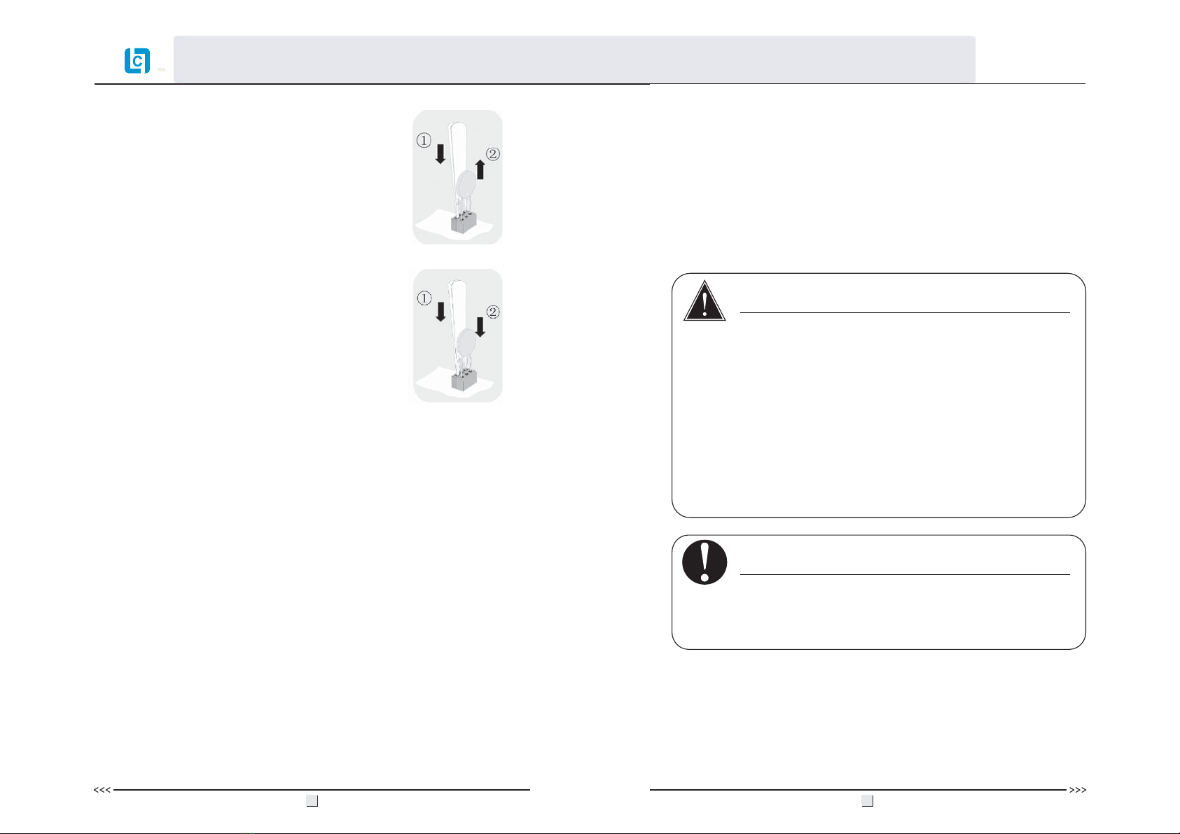
Install:
Use specified tool and insert it to three holes in
the left side of the varistor, then press it to the
end.
Press the varistor in.
Figure 5.11
3. Remove and install the varistors
Remove:
First use specified tool and insert it to three holes
in the left side of the varistor, then press it to the
end.
Pull the varistor out.
Figure 5.10
·
Electrical connections shall be carried out in
accordance with the applicable regulations, such as
conductor sections, fuses, earthing protection.
NOTICE
DANGER
·
·
·
DANGER to life due to potential fire or electricity
shock.
With the inverter powered, comply with all prevailing
national regulations on accidents prevention.
This inverter will be directly connected with HIGH
VOLTAGE power generation device; the installation
must be performed by qualified personnel only in
compliance with national and local standards and
regulations.
21 22
6. ELECTRICAL CONNECTION
6.1 SAFETY
5.9 OVERVOLTAGE CATEGORY
Overvoltage category III applies to SAJ grid - tie solar inverter AC
terminals. For PV circuits in general, Overvoltage Category II is assumed.
4. Put the lid back and re-screw all 4 screws, make sure the lid is tightening to
the inverter.
5.6 MAINTENANCE
Ask your installer to check for proper inverter operation at regular
intervals.
5.7 MODULE TECHNOLOGY
SAJ grid - tie solar inverters provide the optimal solution for any module.
Transformerless-type SAJ grid-tie solar inverters are designed for ungrounded
modules, especially for the crystalline silicon photovoltaic modules, such as
monocrystalline silicon and polycrystalline silicon. While the thin-film
modules are not suitable for SAJ transformerless inverters.
5.8 POLLUTION DEGREE
SAJ grid-tie solar inverters comply with the pollution degree 3.
User Manual
ADD:2OOM#./'UAN9U2OAD4ANG$ONG4IAN(E$ISTRICT'UANG:HOU'UANG$ONG#HINA
Quotation Sheet NO.:20120611
www.lowcarbon-idea.com [email protected]
23 24
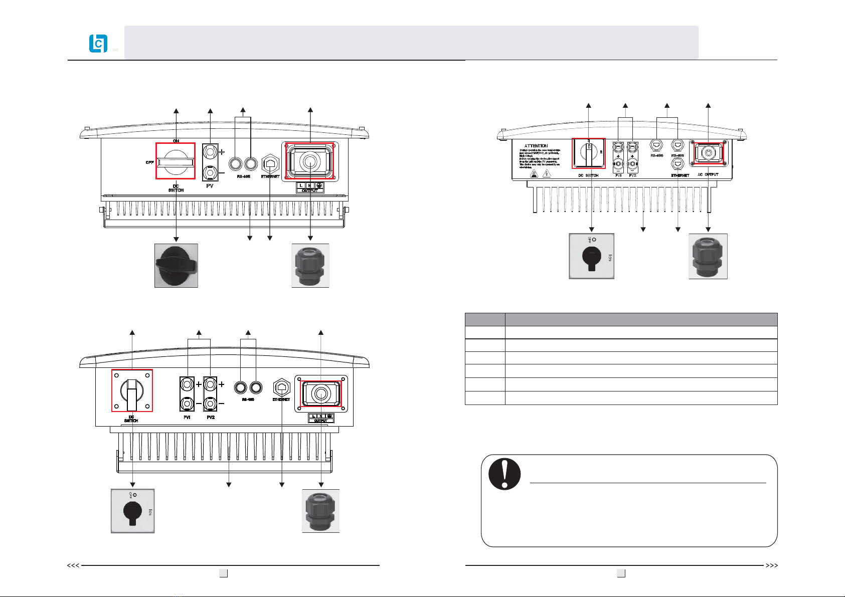
6.2 OVERVIEW OF CONNECTION AREA
Bottom:
Object
A
B
D
E
F
C
Description
DC switch to turn off the inverter manually(optional)
DC input
Plug for connecting the RS485 communication module
Plug for connecting communication module
AC output
Heat sink
Ethernet (optional)
Figure 6.1
ABC
D
E
F
Sununo-TL3KA/4KA/4.4K/5K
Bottom:
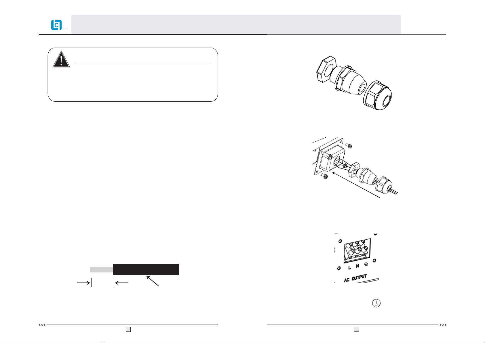
6.3 AC SIDE CONNECTION
NOTICE
·
The cross-section of the AC cable should be more than 12
AWG for Sununo-TL1.5K/2K and 10 AWG for
Sununo-TL3KB/4KB/3KA/4KA/4.4K/5K,
and Cable Rangeφ9-14mm.
Bottom:
Sununo-TL1.5K/2K
Sununo-TL 3KB/4KB
E
F
BC
FD
ABCE
D
A
User Manual
ADD:2OOM#./'UAN9U2OAD4ANG$ONG4IAN(E$ISTRICT'UANG:HOU'UANG$ONG#HINA
Quotation Sheet NO.:20120611
www.lowcarbon-idea.com [email protected]
25 26
Assembly Instructions:
1. Strip the cable with the length 0.276 inches (9/32″) - (7mm) and please be
careful NOT to nick conductors.
Figure 6.2
Integrated RCD and RCM
Current Protective Device) and RCM (Residual Current Operated Monitor).
The current sensor will detect the volume of the leakage current and compare it
with the pre-set value. If the leakage current is above the permitted range, the
RCD will disconnect the inverter from the AC load.
The SAJ grid-tie solar inverter will probably cause a DC current in the external
protective earthing conductor. Where a residual current-operated protective
(RCD) or monitoring (RCM) device is used for protection in a case of direct or
indirect contact, only an RCD or RCM of Type B is allowed on the supply side
of this product. Provided an AC current or pulse current is caused in the
external protective earthing conductor, an RCD or RCM of Type AC or Type A
as alternative can be permitted putting into use.
·
·Never
DANGER to life due to potential fire or electricity
shock.
connect or disconnect the connectors under
load.
DANGER
Cable
0.276 inches(9/32″)-(7mm)
2. Screw off and separate each component of AC connector as follows.
3. Pass the cable through each component from right to the left as follows.
Tighten the screws with 3.0N·m torque.
4. Use a screw driver and loose the three screws at the side of the straight plug.
Then insert the stripped N, L and PE cable accordingly to the corresponding
position and fully tighten the screws.
Connect L, N and protective conductor ( ) to the AC terminal in
accordance with the label.
Figure 6.3
Figure 6.4
Figure 6.5
The SAJ grid - tie solar inverter is equipped with integrated RCD (Residual
User Manual
ADD:2OOM#./'UAN9U2OAD4ANG$ONG4IAN(E$ISTRICT'UANG:HOU'UANG$ONG#HINA
Quotation Sheet NO.:20120611
www.lowcarbon-idea.com [email protected]

5. Aim the terminals on the straight plug to the holes of the grommet, and then
compress them together.
6. Finally, connect the straight plug to the AC terminal on inverter. Pay
attention to the polarity of the terminals to avoid wrong connecting.
6.4 DC SIDE CONNECTION
The cable length on DC side should not exceed 30 m.
Figure 6.6
Figure 6.7
To do this , the insulated earthing conductor must be 5mm longer than the
insulated L and N conductors! L and N must not be swapped.The ground wire
shall be larger than phase conductor.
27 28
Sununo-TL1.5K/2K
Sununo-TL 3KB/4KB
Sununo-TL3KA/4KA/4.4K/5K
NOTE:
User Manual
ADD:2OOM#./'UAN9U2OAD4ANG$ONG4IAN(E$ISTRICT'UANG:HOU'UANG$ONG#HINA
Quotation Sheet NO.:20120611
www.lowcarbon-idea.com [email protected]
For Sununo – TL 1.5K/2K/3KB/4KB, there is just one MPP Tracker. These
single MPPT inverters require same type module same quantity, identical
alignment and tilt.
For Sununo – TL 3KA/4KA/4.4K/5K, there are two MPP Trackers for the two
string inputs. Unlike the traditional single MPPT inverters which require same
type module, same quantity, identical alignment and tilt, the multi-MPPT SAJ
grid-tie inverters can deal with different solar modules, different quantity,
different alignment and tilt, thus can withstand harshest environmental
conditions.
with
Inverter Type
Sununo-TL1.5K
Sununo-TL2K
Sununo-TL3KB
Sununo-TL4KB
Sununo-TL3KA
Sununo-TL4KA
Sununo-TL4.4K
Sununo-TL5K
MPP Tracker
1
Max.DC Voltage
550V
30
·
connected at input zone 1 and the negative pole at input
zone 2, this is called a mixed connection.
·Only connect strings at one input zone and never mix
the input zones 1 and 2!
For instance, if the positive pole of a string is
NOTICE
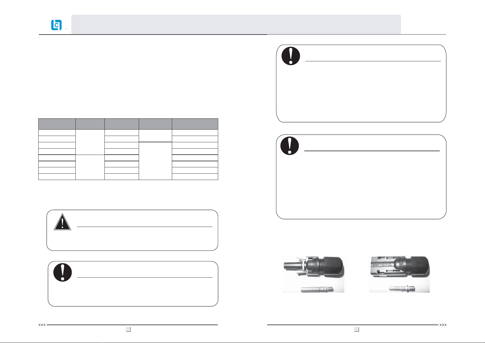
The DC connectors come pre-assembled and the caps are loose. The whole
connector will include the male side and female side as showed below:
Figure 6.8
·
make sure the inverter is isolated and disconnected from
the PV source and AC grid.
·
Before electrical connection setup, installer shall
The inverter may only be operated with PV generators
(Class A PV modules according to IEC 61730 and
cabling) of protection class II. Do not connect any
sources of energy other than PV modules to the inverter.
NOTICE
·
please use the sealing plug to seal the left DC input set to
ensure the inverter IP 65 protection.
If only one string input is used for DC connection,
NOTICE
·
·
DANGER to life due to potential fire or electricity shock.
Never connect or disconnect the connectors under load.
DANGER
Max. DC
Power (W)
Max.DC
Current/per string(A)
2
1800
2300
3400
4500
3200
4200
4600
5200
480V
11
12
17
20
16A/15A
21A/15A
23A/16A
26A/16A
Female side connector (F)
Male side connector (M)
29
No mixed connections between input zones(for Sununo-
TL 3KB/4KB and Sununo-L3KA/4KA/4.4K/5K).
User Manual
ADD:2OOM#./'UAN9U2OAD4ANG$ONG4IAN(E$ISTRICT'UANG:HOU'UANG$ONG#HINA
Quotation Sheet NO.:20120611
www.lowcarbon-idea.com [email protected]
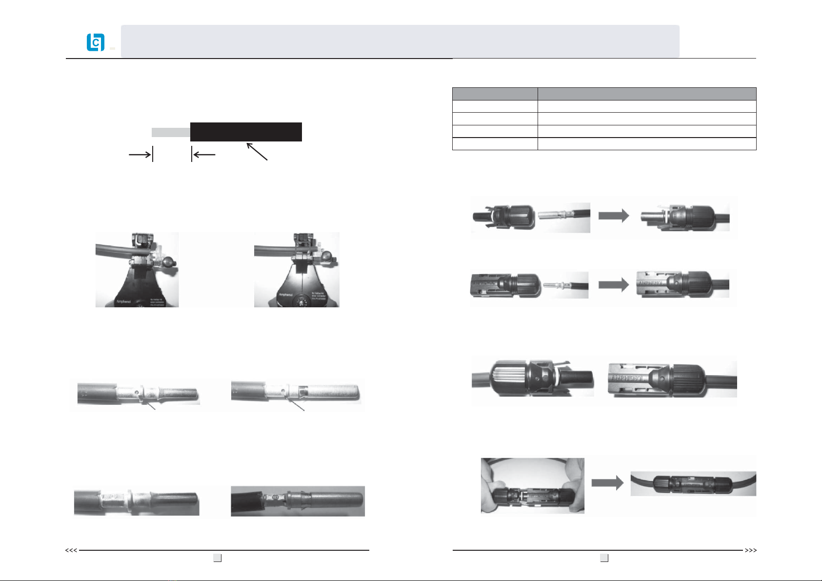
4. Insert contact cable assembly into back of male and female connector. A
“click” should be heard or felt when the contact cable assembly is seated
correctly. See below figures.
5. Wrest the cap by using the torque of 2.6~2.9N·m.
6. After wrested the cap tightly, align the 2 half connectors and mate them
together by hand until a “click” is heard or felt.
Female side connector (F)
Figure 6.16
Male side connector (M)
Figure 6.15
Figure 6.17
Figure 6.18
31 32
Use specified strip tool in this step. Adjust the strip stopper and put the cable in
corresponding notch to strip the length of 7mm. See below figures.
2. Insert stripped cable into contact barrel and insure all conductor strands are
captured in the contact barrel and the conductors are visible in the contact
barrel observation hole. See below figures.
3. Crimp contact barrel by using the hex crimping die. ensure it is fixed.See
below figures.
Figure 6.10 Figure 6.11
Barrel observation hole
Conductor should be visible
Barrel observation hole
Conductor should be visible
Figure 6.12 Figure 6.13
Figure 6.14
Cable pull – out force requirement
Min. 310 N (70 Lbs)
Min. 400 N (90 Lbs)
Min. 450 N (100 Lbs)
Min. 500 N (110 Lbs)
Cable Size
2.5 mm
4 mm
6 mm
10 mm
2
2
2
2
Crimped pin contact Crimped socket contact
Pin contact Socket contact
Cable requirements:
Assembly Instructions:
1. Strip the cable with the length 0.276 inches (9/32")-(7mm) and please be
careful NOT to nick conductors.
Figure 6.9
Cable
0.276 inches(9/32")-(7mm)
User Manual
ADD:2OOM#./'UAN9U2OAD4ANG$ONG4IAN(E$ISTRICT'UANG:HOU'UANG$ONG#HINA
Quotation Sheet NO.:20120611
www.lowcarbon-idea.com [email protected]
6.5 DC SIDE DISCONNECTION
When the separation of DC connectors is necessary, please separate the
connector by hands. See below figures.
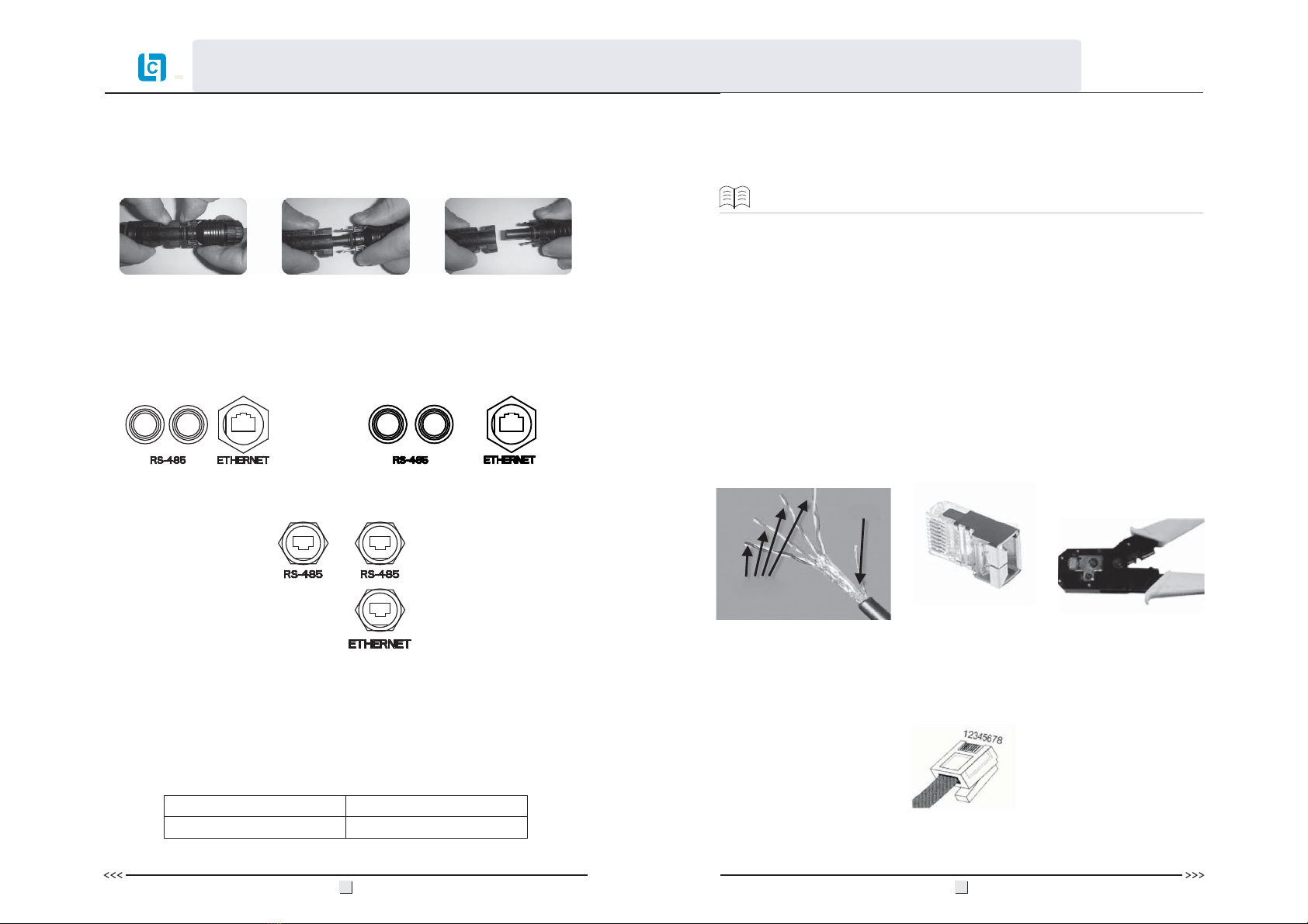
6.6 COMMUNICATION AND MONITORING SETTING
There are 3 communication plugs in the bottom side of the SAJ grid-tie
solar inverter:
The inverter support two communications: Ethernet and RS485
Communication Address:
(optional)
33 34
Figure 6.19 Figure 6.20 Figure 6.21
Figure 6.22
Sununo-TL1.5K/2K Sununo-TL 3KB/4KB
Sununo-TL 3KA/4KA/4.4K/5K
Figure 6.23
RS485 default address
IP default address
1
192.168.1.111
NOTE:
Four STP
Shield layers
RJ-45 plug Wire cutter
Figure 6.24
RJ-45 plug (spring downward)
Each inverter has a default address. The user can alter the communication
address in one’s need to realize monitoring
Make sure each inverter address is sole and effective. It is not using the
same address on two or more inverter while they are connecting together in the
same network, otherwise it will cause a failure of monitoring.
(optional)
Ethernet provides a convenient way for data monitoring. In order to realize this
function, except a PC, a Router/ Switch, user needs to buy a finished cable
(already connected with RJ45 plugs), and ensure two ends of this cable are
crossover, or else user shall DIY make a crossover cable as follows.
User shall prepare a Cat5e STP (shield twisted pair cables<category5>), two
RJ45 plugs and a wire cutter (see figure 6.23).
multi-inverter.
allowed
6.6.1 Ethernet Setting
HUB/
Mark the RJ45 pins from left to right as the shown sequence(see figure 6.24).
User Manual
ADD:2OOM#./'UAN9U2OAD4ANG$ONG4IAN(E$ISTRICT'UANG:HOU'UANG$ONG#HINA
Quotation Sheet NO.:20120611
www.lowcarbon-idea.com [email protected]

35 36
3. Tighten up the two ends by the wire cutter and finish making a crossover
cable.
4. Connect the inverter and the Router/HUB/Switch together with the
crossover cable.
Figure 6.26
2. Insert the other end of STP cable into another RJ45 plug as the below
sequence, and make sure the shield layer fully touched the metal shell. (See
figure 6.26)
Figure 6.25
PC
lnverter Router/HUB/Switch
Note:
If there are multi inverters for monitoring via Ethernet, user can make the same
crossover cables to connect two or more inverters as shown below
Router/HUB/Switch
Figure 6.27
6.6.2 RS485 Setting
------
485 to 232 PC
SAJ lnverter
There are two kinds of connections to realize the RS485 communication.
(Ⅰ) Prepare a Cat5e STP cable and use a connector (If it is accessory in the
inverter pack)
Figure 6.28
Divide it into three parts:
Figure 6.29
One end of the cable: connect with the inverter
1. Cut off outside layer of one end of the Cat5e STP cable to reveal the wires.
2. Use the blue & white wire, blue wire and the metal shield layer, cut off their
layer to make the metal part outside.
3. Make the blue & white wire connect with terminal 1, the blue wire with
terminal 2, and the metal shield layer with terminal 3, then fasten them with
solder tin.
Brown
Blue
White & Blue
White & Brown
1
2
3
4
5
6
7
8
White &Green
Green
White & Orange
Orange
Pin No. of RJ45 Wire color
Brown
White & Orange
Orange
White & Green
Blue
White & Blue
Green
White & Brown
1
2
3
4
5
6
7
8
Pin No. of RJ45 Wire color
12
3
terminal socket
plastic sleeve
1. Cut off outside envelope of the STP cable to reveal the eight wires, make the
end of wire straight, insert one end into a RJ45 plug as the below sequence
(comply with EIT/568B standard), and make sure the shield layer fully
touched the metal shell (See figure 6.25).
12345678
12345678
User Manual
ADD:2OOM#./'UAN9U2OAD4ANG$ONG4IAN(E$ISTRICT'UANG:HOU'UANG$ONG#HINA
Quotation Sheet NO.:20120611
www.lowcarbon-idea.com [email protected]


