Apollo Solar TSW User manual

2
Components of the Apollo Telecom Power System
Step1
Start with enough Solar and Battery
to keep the Tower running for 3 days.
Step 2 –If the space
limits the PV Array, add
a small (6 - 12kW)
Generator for back up to
fill in the difference.
The Tower BTS
needs 48V DC at
typically 2kW.
Deep Cycle Batteries provide
continuous DC power.
Charge
Controllers,
Switchgear
and Remote
Monitoring
The losses in the battery are not critical
because the Solar energy is essentially free.

3
APOLLO SOLAR –REMOTE ENERGY SYSTEM –SYSTEM WIRING DIAGRAM
VOLTAGE SENSE +
VOLTAGE SENSE -
SYSTEM POWER +
SYSTEM POWER -
TEMPERATURE SENSE
BATTERY +48V
BATTERY -48V
GSM ANTENNA
FOR MODEM
OUTSIDE OF
CABINET
6 ALARM OUTPUTS
PAIRS OF DRY
CONTACTS
EARTH
GROUND
PV THEFT ALARM
This wire is stitched through the frame
of every PV module. Breaking the wire
triggers the alarm.
End-of-Life switch on MOVs in the
Combiner Box are wired in series.
Any MOV can trigger an alarm.
PV INPUTS
EXT ALARM
INPUTS
PV INPUTS TO THE T80HV CHARGE
CONTROLLERS ARE 75V TO 180V
AT 50 AMPS MAX EACH
GROUNDING NOTE:
The PV Array Frames and the Racking System
must be tied directly to Earth Ground.
The Combiner Box Ground should run with the
power wires back to the Charger Cabinet.
SYSTEM
EARTH
GROUND
48V DC ESSENTIAL
LOADS 50A
NON-ESSENTIAL
LOADS 50A
AA AB
AF AG
P T
U V
AH AI
AJ AK
M
N
J
K
G
H
AD
AE
70
S1 S2S3 S4
+ - + - + -
E
C
F
C
MOV EOL
PV THEFT ALARM
48 VOLT BATTERY BANK
WITH 2 STRINGS OF BATTERIES
BY OTHERS
APOLLO
IRRADIANCE
SENSOR AT
PV ARRAY
BATTERY BREAKER TRIPPED
LOAD BREAKER TRIPPED
LOW BATTERY VOLTAGE
HIGH CABINET TEMPERATURE
HIGH BATTERY VOLTAGE
HIGH BATTERY TEMPERATURE
X
S
+RED
-BLACK
GND
+ -
PAIR OF AWG 4/0
PAIR OF AWG 4/0
+ - + -
APOLLO PVT
CABINET
+ -+ -
+ - + - APOLLO TEMP
SENSOR ON
SIDE OF
BATTERY
250A
BATTERY
BREAKERS
BK
48 VOLT 10kW
RECTIFIER
BY OTHERS
48V DC
48V DC
+
-
+
-
+
-230VAC
NEUTRAL
GROUND
GROUND
230VAC 50Hz
DIESEL
GENERATOR
BY OTHERS
BJ
CONTACT CLOSURE TO START GENERATOR
GND
PV ARRAY
APOLLO COMBINER
BOX WITH SURGE
PROTECTION DEVICE
PV ARRAY
APOLLO COMBINER
BOX WITH SURGE
PROTECTION DEVICE
PV ARRAY
APOLLO COMBINER
BOX WITH SURGE
PROTECTION DEVICE
PV ARRAY
APOLLO COMBINER
BOX WITH SURGE
PROTECTION DEVICE
23 F. J. Clarke Circle
Bethel, Connecticut 06801
USA +1 203 790 6400
www.ApolloSolar.com
27-MAR-2017 J. PFEIFER
ENERGY SYSTEM BLOCK DIAGRAM
REV 1
WITH HYBRID SOLAR / DIESEL OPTION
RECTIFIER
INPUT
GND
GND
GND

4
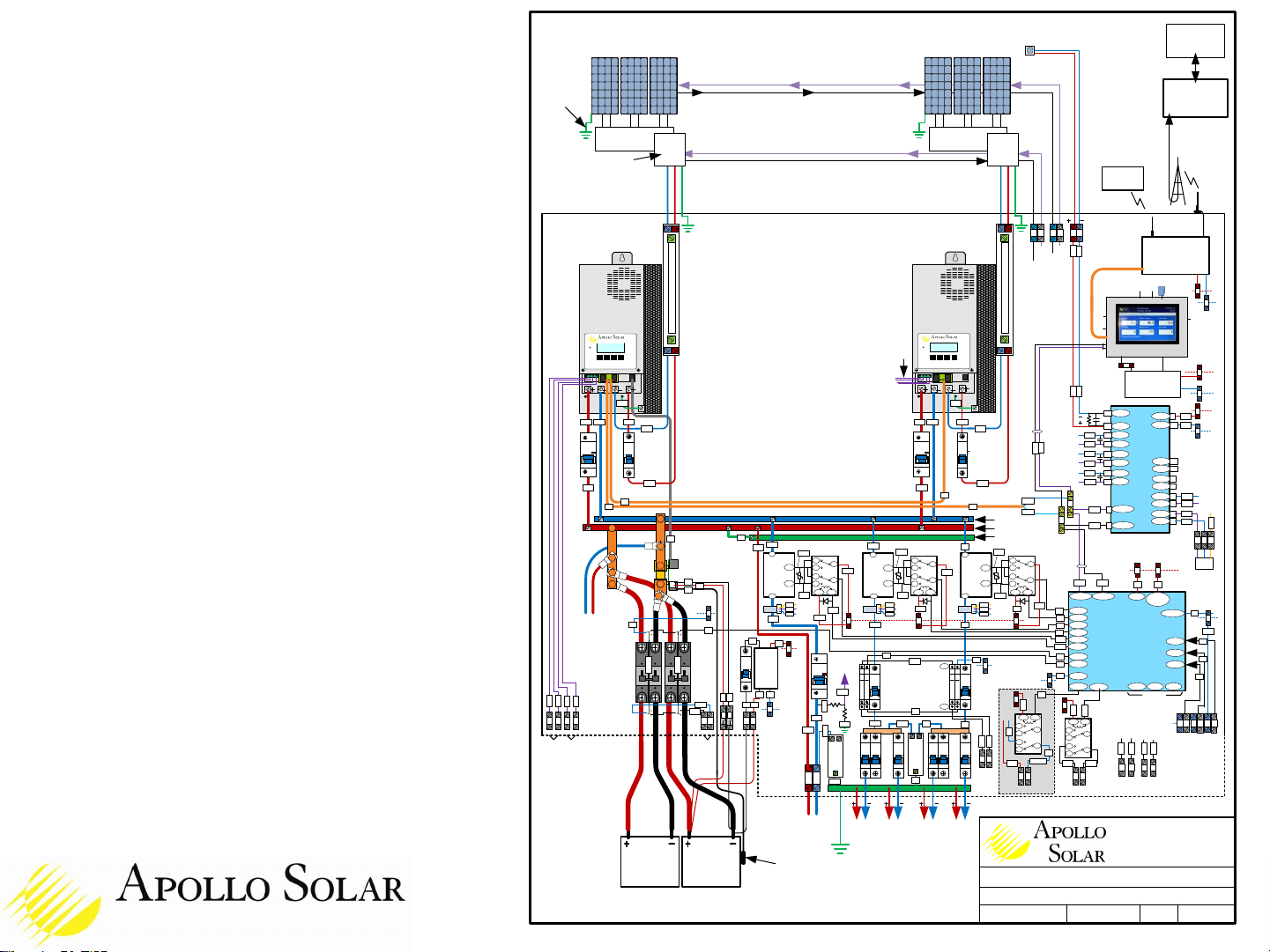
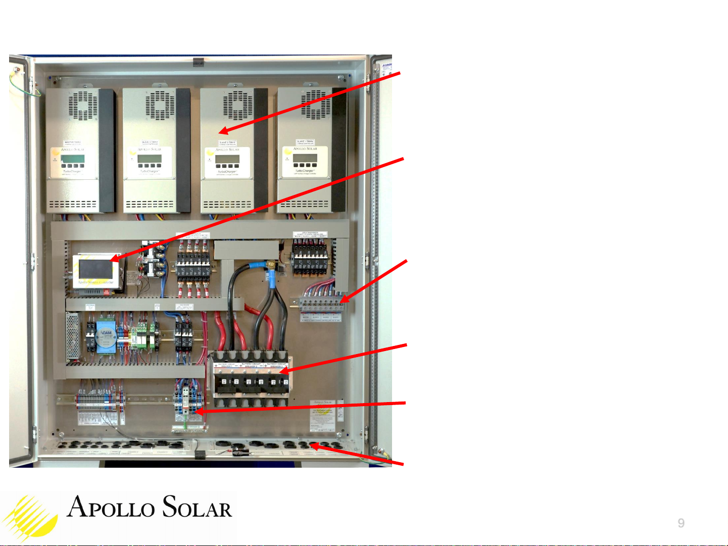
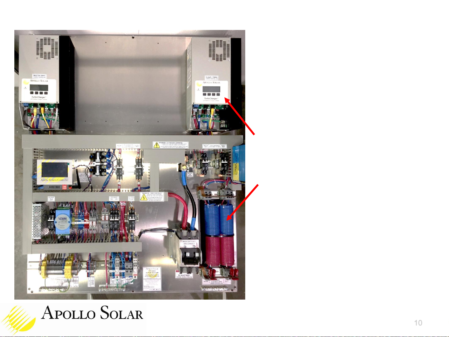
Wiring of the Apollo Solar Cabinet
A good grounding system is essential.
GOOD GROUNDS -- The quality of the connection to earth ground is the single most
important issue. The resistance from the ground system to the earth must be very low. You
will need many ground rods and if the soil is dry and/or sandy, extreme measures, such as
adding carbon dust, will be required to get a reasonably low resistance.
EQUAL POTENTIAL GROUNDS -- Equal Potential Grounding is an important rule. This
means a single “star point” ground in your equipment with the best earth connection you
have connected to that same star point. Use the Panel in the Apollo Cabinet as the star
point ground.
GROUND WIRING -- All ground wires must be short, thick and straight so they are free of
resistance and inductance. Any coil in a ground wire makes an inductance which prohibits
the fast surge from going to ground.
PREVENT RODENT DAMAGE –We recommend running all the wiring to the Cabinet from
the PV Array, the Battery Enclosures and the BTS Equipment Rack in covered metal wiring
trays. Rodents like to eat the insulation from wires. It is the largest single cause of field
problems.

5
Apollo Solar - Energy System Cabinet
The Apollo Gen 4 PVT Systems include all of the
electronics in a single cabinet for easy installation.
The cabinets are powder coated steel and sealed
to meet IP66 and are intended to be outdoors,
typically in the shade, under the PV array.
The cabinet is 1000mm wide x 300mm deep x
1200mm tall. It is shown here with 450mm legs.
They can also be hung from the ground-mounted
PV support system.
All of the cables exit from the bottom using water-
proof glands. The cables should be covered in
rodent-proof metallic braded shields and run
inside covered metal trays to the PV Combiners,
the Battery Enclosures and the BTS Load rack.
Multiple cabinets can be installed side by side, or
back to back as shown here.

Detailed Block Diagram of
Apollo Hybrid Energy System
This is the actual diagram of
systems built. It can be expanded to
harvest solar energy up to 60kW
and support tower loads up to 6kW.
The Apollo system provides all the
elements to provide reliable energy
for the tower.
Options allow our system to provide
all possible features cost effectively.
The input can be Solar and
Generator.
EARTH GROUND BUS
Copyright 2015, 2016, 2017 Apollo Solar, Inc.
ALL INFORMATION ON THIS DRAWING
IS CONFIDENTIAL AND PROPRIETARY
TO APOLLO SOLAR, INC.
APOLLO SOLAR - GEN4 HYBRID SYSTEM –BLOCK DIAGRAM
EARTH
GROUND
PV ARRAY
FRAME SERIES
WIRE
APOLLO
BATTERY
TEMPERATURE
SENSOR
500A
SHUNT
AUX
CONTACTS
FOR MOV
END OF
LIFE
ESSENTIAL
LOADS
50A MAX
ALL CIRCUIT BREAKERS ARE
IEC / EN 60947-2 LISTED
NEG BUS
POS BUS
BUS BAR
POSITIVE
GROUND POINT
A
71
CB5
72
COM
N.C.
ANY PC
SERVER WITH
APOLLO
SOFTWARE AND
DATABASE
CB2
BATTERY
HIGH TEMP
ENCLOSURE
HIGH TEMP
DRY
CONTACT
ALARM
OUTPUTS
137
140
139
138
ASNET
CAT5
98
850 or
900MHz
EXT
ANTENNA
A2-
A1+
A2-
A1+
12
24
14
22 21
11
160A
LATCHING
CONTACTOR
RY6
RY7
A
CB18
LOAD
BKR
TRIP
ALARM
BATTERY
BREAKER
TRIP ALARM
BAT TRIP
ALARM
1
2+
40
A2-
A1+
A2-
A1+
12
24
14
22 21
11
160A
LATCHING
CONTACTOR
RY4
RY5 124
125
68
69
70
144
145
146
155
154
149
SURGE PROTECTOR
DEVICES WITH AUX
CONTACTS ON MOVS IN
COMBINER BOXES
TO ADDITIONAL ALARM OUPUTS
PV ARRAY
EARTH
GROUND
MOVs
PV ARRAY
1
29
24V
24V
RETURN
A
C
CONNECTIONS TO 2ND
CABINET IF REQD
147
EARTH BUS
IRRADIANCE
SENSOR
X
S
4/0
BUS BAR
95mm2
APOLLO
SHUNT
BOARD
24V
RETURN
122
F
E
68
69
5 AMP FUSES
NON-ESSENTIAL
LOADS
50A MAX
135
136
C
C
DOOR
SWITCH
TWISTED
PAIR
MOVs
PV ARRAY
5 VDC
REGULATOR
A
C
24V
5V
GSM +WiFi
GATEWAY
WiFi
ANT
A
C
24V
APOLLO SYSTEM CONROLLER
SD
USB
USB
RS485
TWISTED PAIR
BLUE
DATA-
FROM IRR
SENSOR
BLU/
WHT
DATA+
136
135
79A
79B
134
133
USB
ETHERNET
CAT5
24V
A
D
A
C
RS485
ALARM
INPUTS
E
F
C
C
J
K
M
N
BATTERY
48 VOLTS BATTERY
48 VOLTS
PARALLEL BATTERY STRINGS
AJ
AK
U
V
250A
BREAKER
ON EACH
BATTERY
STRING
47
2/0
COM
N.C.
AUX
COM
N.C. TRIP
COM
N.C. TRIP COM
N.C.
AUX
67
CB20
CB21
6
163
162
AA
AB
23 F. J. Clarke Circle
Bethel, Connecticut, 06801
USA +1 203 790-6400
www.ApolloSolar.com
6-MAR-2017 J. PFEIFER
REV 62
GEN4 POS GND HYBRID BLOCK DIAG
SOLENE –GUINEA CONAKRY
11
14
CITEL 48V
MOV SPD
150
AF
AG
157
156
44
ON
16A
ON
63A
ON
32A
UP TO 5 LOAD
BREAKERS TOTAL
ON
16A
ON
63A
ON
32A
UP TO 5 LOAD
BREAKERS TOTAL
DC
DISTRIBUTION
BREAKERS
ON
16A C24V
RETURN C
8 CH
24BIT A/D
CONV
130 DATA-
8
129 DATA+
7
.1uf
100ohm
IN 0-
IN 0+
12
11 24V
141 A
9
PW+
24V
RETURN
142 C
GND 10
IN 7+
IN 7- 6
5
IN 6+
IN 6- 4
3
IN 5+
IN 5- 1
2
IN 4+
IN 4- 19
20 SPARE
AMBIENT
TEMP SENSOR
TO LEM CURRENT
SENSORS
PV ARRAY
APOLLO
COMBINER SPD
APOLLO SOLAR
T80HV MPPT
CHARGE
CONTROLLER
MASTER
CB11
81
84 83
88
CB10
82
87
85
ON
125VDC
100A
APOLLO 50AMP SPD
ON
63A
250V
PV ARRAY
APOLLO
COMBINER SPD
APOLLO SOLAR
T80HV MPPT
CHARGE
CONTROLLER
SLAVE 1
CB13
91
94 93
88
CB12
92
97
95
ON
125VDC
100A
APOLLO 50AMP SPD
ON
63A
250V
22
DIGITAL I/O
8 DRY CONTACT
INPUTS,
8 OPEN COLL
OUTPUTS
26
25
24
21 17
16
15
27
DO 2
DO 3
DO 4
DI 0
DI 1
DO 0
DO 1
DO 5
DI 4
DI 3
DI 2
DI 5
+Vs
DATA+ DATA-
GND
DO 6
DI 7
DO 7
DI 6
SPARES
D.GND
DO
COM
7
19
131 132
23 126
C
24V
RETURN
22
18
INTERNET
INTERNET
LAPTOP
WiFi
LOCAL
GSM
TOWER
IN 3+
18
243 IN 3-
17246
IN 2+
16
239 IN 2-
242 15
IN 1+
14
235 IN 1-
13
238
41
LOAD1
LOAD2
DG IN SPARE
DG V
SENSE
Z
Y
63
A2-
A1+
A2-
A1+
12
24
14
22 21
11
160A
LATCHING
CONTACTOR
RY
RY
ON
125VDC
100A
48VDC
INPUT FROM
RECTIFIER
100A MAX
2+
CITEL 48V
MOV SPD
TO A/D
CH6-
PIN4
19K
1K
A
2
1
43
ON
63A
250V
OF
14
12
11
AUX D
OF
14
12
11
AUX C
ON
63A
250V
OF
14
12
11
AUX B
OF
14
12
11
AUX A
35
6
21
C
22
4
3
HIGH BAT
VOLTAGE
LOW BAT
VOLTAGE
ALARM DRY CONTACTS
160
161
158
159
P
T
AH
AI
AUX1 AUX2
TO AUX RELAYS
ON T80HV SLAVE 1
A2-
A1+
12
24
14
22 21
11
GEN START
A
247
248
249 250
BK
BJ
RY10
255 256
257
260
259
258
230
231
123
261
261
262
263
232
234
ISOLATED
24V DC
SUPPLY
233
233
A1+
A1+
A2-A2-
2+
1
LEM 235 +5V
C
A/D14
237
236
LEM 243
244
245 +5V
C
A/D18 LEM 239 A/D16
+5V
C
240
241
89
79 89 ASNET CAT5 79
.1uf
256
CF
CE
CD
LM35
253
+5V
252
251
+48V BUS
-48V BUS
20
A2-
A1+
12
24
14
22 21
11
48V FANS
A
37
64
Q
R
RY3
66 FUSE
38
FANS AND GEN START
ARE OPTIONS
230
264

Assembly Drawing of Apollo
Hybrid Energy System
For comparison, many of the popular
options are shown on this drawing. If
an option is not purchased, the space
for it is simply not used.
This drawing is valuable for support
since it calls out all the numbers of
each wire.
A larger version of this drawing is
included in the Installation Manual.
The 10 DC Distribution Breakers are
shown at the bottom center. They may
not all be used at every site.
This drawing shows 3 Battery
Breakers which is the most that will fit.
EARTH
GROUND
ALARMS
ALARM OUTPUTS
DOOR
COMMON
BAT BREAKER 162
163
AA
AB
LOAD BREAKER 157
156
AF
AG
LOW BAT VOLT 158
159
P
T
CABINET TEMP 139
140
U
V
HIGH BAT VOLT 160
161
AH
AI
BAT HIGH TEMP 137
138
AJ
AK
C126
18
D
DLAH-24
s
s
EQP
LINE
+
-
IRRADIANCE
SENSOR X
S136
135
DLAH-24
s
s
EQP
LINE
ALARM
INPUTS
COMMON DLAH-24
s
s
EQP
LINE
F
C
PV ARRAY
MOVs
COMMON 16
17
C
C6
5
+ -
BATTERY FUSE
FUSE 69
68
N
M
67
63
K
J
+ -
BATTERY
TEMP
SENSOR
252
251
CE
CF
253
CD
12
A2
A1
LOAD 2
12
A2
A1
LOAD 1
12
A2
A1
RECTIFIER
INPUT
150
mm
150
mm
175
mm
120mm
+ - + - + - + -
MASTER
T80HV
SLAVE 3
T80HV
SLAVE 2
T80HV
SLAVE 1
T80HV
UP TO AWG 0,
50mm2
BATTERY WIRES ARE 4/0 or 95mm2INPUTS FROM
PV COMBINER
BOXES
440mm
71
AWG
#8
560mm
930mm
+ -
BAT 1 + -
BAT 2 + -
BAT 3
24 VOLT 2.1 AMP
POWER SUPPLY
463
47 150
NON ESSENTIAL
LOADS
50A TOTAL
43 43
149
41
147
6
21
35
156
157
35
PV
IN
BAT
OUT GND
TurboCharger
T80HV
MASTER
79
82
83
71
88
PV
IN
BAT
OUT GND
TurboCharger
T80HV
SLAVE 1
PV
IN
BAT
OUT GND
TurboCharger
T80HV
SLAVE 2
108
105
104
PV
IN
BAT
OUT GND
TurboCharger
T80HV
SLAVE 3
118
+48V IN
-48V IN
GND
-24V OUT
+24V OUT
3
4
2
1
40
146
85
95
105
107
117 115
114
104
94
84
85
89
137
138
140
139
95
94
89
99
92
93
98
102
103
112
114
113
115
99
161
160
159
158
93
103
113
83
81
82
91
92
102
101
111
112
TO 1, 2 OR 3 PARALLEL STRINGS
OF BATTERIES
450mm
149
GND
TO
BATTERY
109
109
GSM ANT WiFi ANT
44
A
NOTE: DLAH SURGE PROTECTORS
WILL TAKE AWG14 (2mm) WIRES.
21T AWG8
21T AWG8
21T AWG8
21T AWG8
20KA
MOV
20KA
MOV
20KA
MOV
20KA
MOV
20KA
MOV
20KA
MOV
20KA
MOV
20KA
MOV
20KA
MOV
20KA
MOV
20KA
MOV
20KA
MOV
12 22
11 21
14 24
A1 A2
LOAD 1
25
29 122 125
124 26
12 22
11 21
14 24
A1 A2
23
155 154 145
144 24
72
DS230S-
48DC SPD
RECTIFIER +
48V DC IN -
BAT TEMP SENSOR
B/W
BLUE 79
Z
Y
131
132 79A
79B 133
134
129
130
TWISTED
PAIR
69
68
174 172 171 170 169
173
41
147
144
5V
REG
+24
GND
+5V
123
235
236
237
239
240
241
12 22
11 21
14 24
A1 A2
RY10
GEN
START
247
248
249
250
C
C
A
A
C
A
15
27
B
155
29 154
37
2
141
B
C
122
B
142
C
164
165
168
238 236
240
244
242
246
237 241
245
170
169
169
167 7
19
166 168
170
A247
252 254
253
230
230
12 22
11 21
14 24
A1 A2
256
255 257 258
259 260
TO
A/D
243
244
245
97
255 257
259
258
264
126
1
LOAD 2
RECTIFIER
INPUT
87
ON
125VDC
100A
ON
125VDC
100A
230
231 231
233 233
DS230S-
48DC SPD
ESSENTIAL
LOADS
50A TOTAL
232
234
425
mm
ON
125VDC
100A
DG IN
72
ON
6A
80V
24V
CB2
H
ESSENTIAL
LOADS
ON ON ONON ON
63A
250V
63A
250V
32A
250V
32A
250V
16A
250V
H
ON ON ONON ON
63A
250V
63A
250V
32A
250V
32A
250V
16A
250V
NON-ESSENTIAL
LOADS
LEM
146
146
LEM
40
40
LEM
AE
10 DC DISTRIBUTION BREAKERS
ON
63A
250V
ON
63A
250V
ON
125VDC
100A ON
63A
250V
ON
63A
250V
ON
125VDC
100A
OF
14
12
11
ON
63A
250V
OF
14
12
11
CB5 OUT
OF
14
12
11
ON
63A
250V
OF
14
12
11
CB18 OUT
123
A/D CONV IS UNDER THE ADAM
DIGITAL I/O
DI COM
DI 1
DI 0
D.GND
DO 7
DO 6
DO 5
DO 4
DO 3
DO 2
DO 1
DO 0
DO COM
DI COM
DI 2
DI 3
DI 4
DI 5
DI 6
DI 7
N/A
INIT*
DATA+ (Y)
DATA- (G)
+Vs R
GND (B)
23
20
722
21
25
26 19
18
17 16
27
15
132 131 24
RS485
ETH
Apollo System Controller
SD
USB
USB
ETH
USB
5V
RS485
134
133 TWISTED
PAIR
201
GSM MODEM SIM
24V
166 167
164 165
145
124 125
NEG
BUS
84
500A
DG START/STOP BJ
BK 250
249
POS BUS
70
263 261
262
350VA INVERTER
2/0
2/0
2/0
70
2/0
2/0
2/0

Assembly Drawing of Apollo
Hybrid Energy System
This drawing shows the components
used for a typical system with 2 charge
controllers.
This drawing shows 1 Battery Breaker.
+ -
BAT
2/0
2/0
2/0
2/0
0.0mm
DATUM
EARTH
GROUND
ALARMS
ALARM OUTPUTS
DOOR
COMMON
BAT BREAKER 162
163
AA
AB
LOAD BREAKER 157
156
AF
AG
LOW BAT VOLT 158
159
P
T
CABINET TEMP 139
140
U
V
HIGH BAT VOLT 160
161
AH
AI
BAT HIGH TEMP 137
138
AJ
AK
C126
18
D
DLAH-24
s
s
EQP
LINE
+
-
IRRADIANCE
SENSOR X
S136
135
DLAH-24
s
s
EQP
LINE
ALARM
INPUTS
COMMON DLAH-24
s
s
EQP
LINE
F
C
PV ARRAY
MOVs
COMMON 16
17
C
C6
5
+ -
BATTERY FUSE
FUSE 69
68
N
M
67
63
K
J
+ -
BATTERY
TEMP
SENSOR
252
251
CE
CF
253
CD
12
A2
A1
LOAD 2
12
A2
A1
LOAD 1
12
A2
A1
RECTIFIER
INPUT
150
mm
150
mm
175
mm
120mm
+ - + - + - + -
MASTER
T80HV
SLAVE 3
T80HV
SLAVE 2
T80HV
SLAVE 1
T80HV
UP TO AWG 0,
50mm2
BATTERY WIRES ARE 4/0 or 95mm2INPUTS FROM
PV COMBINER
BOXES
440mm
71
AWG
#8
560mm
930mm
24 VOLT 2.1 AMP
POWER SUPPLY
463
47 150
NON ESSENTIAL
LOADS
50A TOTAL
43 43
149
41
147
6
21
35
156
157
35
PV
IN
BAT
OUT GND
TurboCharger
T80HV
MASTER
79
82
83
71
88
PV
IN
BAT
OUT GND
TurboCharger
T80HV
SLAVE 1
+48V IN
-48V IN
GND
-24V OUT
+24V OUT
3
4
2
1
40
146
85
95
94
84
85
89
137
138
140
139
95
94
89
92
93
98
161
160
159
158
93
83
81
82
91
92
TO 1, 2 OR 3 PARALLEL STRINGS
OF BATTERIES
450mm
149
GND
TO
BATTERY
GSM ANT WiFi ANT
44
A
NOTE: DLAH SURGE PROTECTORS
WILL TAKE AWG14 (2mm) WIRES.
21T AWG8
21T AWG8
21T AWG8
21T AWG8
12 22
11 21
14 24
A1 A2
LOAD 1
25
29 122 125
124 26
12 22
11 21
14 24
A1 A2
23
155 154 145
144 24
72
DS230S-
48DC SPD
RECTIFIER +
48V DC IN -
BAT TEMP SENSOR
B/W
BLUE 79
Z
Y
131
132 79A
79B 133
134
129
130
TWISTED
PAIR
69
68
41
147
144
5V
REG
+24
GND
+5V
123
235
236
237
239
240
241
12 22
11 21
14 24
A1 A2
RY10
GEN
START
247
248
249
250
C
C
A
A
C
A
15
27
B
155
29 154
37
2
141
B
C
122
B
142
C
164
165
168
238 236
240
244
242
246
237 241
245
170
169
169
167 7
19
166 168
170
A247
252 254
253
230
230
12 22
11 21
14 24
A1 A2
256
255 257 258
259 260
TO
A/D
243
244
245
97
255 257
259
258
264
126
1
LOAD 2
RECTIFIER
INPUT
87
ON
125VDC
100A
ON
125VDC
100A
230
231 231
233 233
DS230S-
48DC SPD
ESSENTIAL
LOADS
50A TOTAL
232
234
425
mm
ON
125VDC
100A
DG IN
72
ON
6A
80V
24V
CB2
H
ESSENTIAL
LOADS
ON ON ONON ON
63A
250V
63A
250V
32A
250V
32A
250V
16A
250V
H
ON ON ONON ON
63A
250V
63A
250V
32A
250V
32A
250V
16A
250V
NON-ESSENTIAL
LOADS
LEM
146
146
LEM
40
40
LEM
AE
10 DC DISTRIBUTION BREAKERS
ON
63A
250V
ON
63A
250V
OF
14
12
11
ON
63A
250V
OF
14
12
11
CB5 OUT
OF
14
12
11
ON
63A
250V
OF
14
12
11
CB18 OUT
123
A/D CONV IS UNDER THE ADAM
DIGITAL I/O
DI COM
DI 1
DI 0
D.GND
DO 7
DO 6
DO 5
DO 4
DO 3
DO 2
DO 1
DO 0
DO COM
DI COM
DI 2
DI 3
DI 4
DI 5
DI 6
DI 7
N/A
INIT*
DATA+ (Y)
DATA- (G)
+Vs R
GND (B)
23
20
722
21
25
26 19
18
17 16
27
15
132 131 24
RS485
ETH
Apollo System Controller
SD
USB
USB
ETH
USB
5V
RS485
134
133 TWISTED
PAIR
201
GSM MODEM SIM
24V
166 167
164 165
145
124 125
NEG
BUS
84
500A
DG START/STOP BJ
BK 250
249
POS BUS
70
263 261
262
70

9
Inside the Apollo Solar Cabinet
SOLAR CHARGE CONTROLLERS
The cabinet will support up to 4 T80HVs
at 4 to 5kW of PV each.
APOLLO SYSTEM CONTROLER –
The ASC provides smart control of all
power sources and distribution along with
the Remote Monitoring.
PV INPUTS –Wire up to AWG 2 or
35mm2can be used from the Combiner
Boxes.
BATTERY BREAKERS –Multiple poles
are provided for parallel battery stacks.
EXTERNAL WIRES –Easy field wiring
to well labeled terminals.
IP67 GLANDS –All wiring comes in
through these proper sized glands.

10
Inside the Apollo Solar Cabinet
2X T80HV Charge Controllers
All other features are standard.
Optional Enhanced Surge Protection
shown.

11
The Apollo Panel in Logical Sections
12
A2
A1
LOAD 2
12
A2
A1
LOAD 1
12
A2
A1
RECTIFIER
INPUT
175
mm
ALARMS
ALARM OUTPUTS
DOOR
COMMON
BAT BREAKER 162
163
AA
AB
LOAD BREAKER 157
156
AF
AG
LOW BAT VOLT 158
159
P
T
CABINET TEMP 139
140
U
V
HIGH BAT VOLT 160
161
AH
AI
BAT HIGH TEMP 137
138
AJ
AK
C126
18
D
DLAH-24
s
s
EQP
LINE
+
-
IRRADIANCE
SENSOR X
S136
135
DLAH-24
s
s
EQP
LINE
ALARM
INPUTS
COMMON DLAH-24
s
s
EQP
LINE
F
C
PV ARRAY
MOVs
COMMON 16
17
C
C6
5
+ -
BATTERY FUSE
FUSE 69
68
N
M
67
63
K
J
+ -
BATTERY
TEMP
SENSOR
252
251
CE
CF
253
CD
150
mm
150
mm
175
mm
120mm
+ - + - + - + -
MASTER
T80HV
SLAVE 3
T80HV
SLAVE 2
T80HV
SLAVE 1
T80HV
UP TO AWG 0,
50mm2
0.0mm
DATUM
BATTERY WIRES ARE 4/0 or 95mm2
EARTH
GROUND
INPUTS FROM
PV COMBINER
BOXES
440mm
71
AWG
#8
560mm
930mm
+ -
BAT 1 + -
BAT 2 + -
BAT 3
24 VOLT 2.1 AMP
POWER SUPPLY
463
47 150
NON ESSENTIAL
LOADS
50A TOTAL
43 43
149
41
147
6
21
35
156
157
35
PV
IN
BAT
OUT GND
TurboCharger
T80HV
MASTER
79
82
83
71
88
PV
IN
BAT
OUT GND
TurboCharger
T80HV
SLAVE 1
PV
IN
BAT
OUT GND
TurboCharger
T80HV
SLAVE 2
108
105
104
PV
IN
BAT
OUT GND
TurboCharger
T80HV
SLAVE 3
118
+48V IN
-48V IN
GND
-24V OUT
+24V OUT
3
4
2
1
40
146
85
95
105
107
117 115
114
104
94
84
85
89
137
138
140
139
95
94
89
99
92
93
98
102
103
112
114
113
115
99
161
160
159
158
93
103
113
83
81
82
91
92
102
101
111
112
TO 1, 2 OR 3 PARALLEL STRINGS
OF BATTERIES
450mm
149
GND
TO
BATTERY
109
109
GSM ANT WiFi ANT
44
38
A
NOTE: DLAH SURGE PROTECTORS
WILL TAKE AWG14 (2mm) WIRES.
21T AWG8
21T AWG8
21T AWG8
21T AWG8
20KA
MOV
20KA
MOV
20KA
MOV
20KA
MOV
20KA
MOV
20KA
MOV
20KA
MOV
20KA
MOV
20KA
MOV
20KA
MOV
20KA
MOV
20KA
MOV
12 22
11 21
14 24
A1 A2
LOAD 1
25
29 122 125
124 26
12 22
11 21
14 24
A1 A2
23
155 154 145
144 24
72
DS230S-
48DC SPD
RECTIFIER +
48V DC IN -
12 22
11 21
14 24
A1 A2
RY3
FAN
RELAY 20
37
38
64
BAT TEMP SENSOR
B/W
BLUE 79
Z
Y
131
132 79A
79B 133
134
129
130
TWISTED
PAIR
69
68
174 172 171 170 169
173
41
147
144
5V
REG
+24
GND
+5V
123
66
235
236
237
239
240
241
12 22
11 21
14 24
A1 A2
RY10
GEN
START
247
248
249
250
C
C
A
A
C
A
15
27
B
155
29 154
37
2
141
B
C
122
B
142
C
164
165
168
238 236
240
244
242
246
237 241
245
170
169
169
167 7
19
166 168
170
A247
252 254
253
230
230
12 22
11 21
14 24
A1 A2
256
255 257 258
259 260
TO
A/D
243
244
245
97
255 257
259
258
264
126
1
LOAD 2
RECTIFIER
INPUT
+ -
87
ON
125VDC
100A
ON
125VDC
100A
230
231 231
233 233
DS230S-
48DC SPD
ESSENTIAL
LOADS
50A TOTAL
232
234
425
mm
ON
125VDC
100A
DG IN
72
ON
6A
80V
24V
CB2
H
ESSENTIAL
LOADS
ON ON ONON ON
63A
250V
63A
250V
32A
250V
32A
250V
16A
250V
H
ON ON ONON ON
63A
250V
63A
250V
32A
250V
32A
250V
16A
250V
NON-ESSENTIAL
LOADS
LEM
146
146
LEM
40
40
LEM
AE
10 DC DISTRIBUTION BREAKERS
48V FANS 66
64
Q
RFUSE
ON
63A
250V
ON
63A
250V
ON
125VDC
100A ON
63A
250V
ON
63A
250V
ON
125VDC
100A
OF
14
12
11
ON
63A
250V
OF
14
12
11
CB5 OUT
OF
14
12
11
ON
63A
250V
OF
14
12
11
CB18 OUT
123
A/D CONV IS UNDER THE ADAM
DIGITAL I/O
DI COM
DI 1
DI 0
D.GND
DO 7
DO 6
DO 5
DO 4
DO 3
DO 2
DO 1
DO 0
DO COM
DI COM
DI 2
DI 3
DI 4
DI 5
DI 6
DI 7
N/A
INIT*
DATA+ (Y)
DATA- (G)
+Vs R
GND (B)
23
20
722
21
25
26 19
18
17 16
27
15
132 131 24
RS485
248
260
256
ETH
Apollo System Controller
SD
USB
USB
ETH
USB
5V
RS485
134
133 TWISTED
PAIR
201
GSM MODEM SIM
24V
166 167
164 165
145
124 125
NEG
BUS
84
500A
DG START/STOP BJ
BK 250
249
POS BUS
70
263 261
262
350VA INVERTER
2/0
2/0
2/0
70
2/0
2/0
2/0
Optional Enhanced
Surge Protection on
PV Inputs
Positive 48V Bus Bar
Negative Bus Bar
and 500A Shunt
T80HV Output 100A
Circuit Breakers
Optional 350VA Pure
Sine Wave Inverter
PV Input 63A
Circuit Breakers
250A Battery
Breakers, 3 pairs
Optional DG/Rectifier
Input & DG Control
Output Contactors
Apollo System
Controller and
GSM Modem
63A Output & 100A
DG Input Breakers
Digital Input/Output
Circuitry and Relays
24V Isolated Power
Supply & Breaker
Optional DC
Distribution Breakers
Alarm Inputs and
Outputs
1 to 4 T80HV
Charge Controllers

12
Apollo Solar Gen 4 Wiring Details
The DC Outputs to the
Essential Load and the Non-
Essential Load are easily
connected to terminals G/H
and AD/AE.
The portable 350VA Inverter
is plugged into terminals O
and W when used.
The smaller terminals are used for
connecting the Irradiance Sensor,
the Alarm signals and the battery
voltage sense wires.
Terminals M and N are fitted with 5
Amp automotive type fuses.
The PV inputs have
screw type connectors
which will accept up to
AWG 2 wires from the
Combiner Boxes.
Torque the screws to
4.6 N-m (40 in-lbs).
The Earth Ground is a
single point with a
terminal strip to
connect to the
external Ground Rod.
Torque the screws to
4.6 N-m (40 in-lbs).

13
Apollo Irradiance Sensor
The Apollo Irradiance Sensor is mounted on top of
the PV Array.
The ASC uses it to calculate the amount of solar
energy available each day.
One of the charts available shows the results.

14
Gen 4 Wiring –Battery Temperature Sensor
The T80HV Charge Controllers use the Battery Temperature to compensate
the charge voltages.
The small Square device comes with tape. Stick this unit to the side of a
battery near the middle of the battery stack. It should be below the level of
the electrolyte.
Plug the 4 pin connector into the RJ-11 Jack on the Shunt Board as shown in
the photo above.

15
Apollo Solar Gen 4 Installation Details
The POSITIVE battery
cables are to the
POSITIVE BUS BAR.
The NEGATIVE battery cables
are to the LOWER TERMINAL
ON THE SHUNT.
The battery cables must be AWG 4/0 or 95mm2 for minimum
voltage drop. The terminals MUST be tightened with a
calibrated torque wrench 20.2 N-m (180 in-lbs.).
The Bus Bars are shown above with their covers removed.
The arrows point to their locations on the Gen 4 Panel.

16
Apollo Solar Gen 4 Wiring Details
The photo shows the wire entry glands in the bottom of the cabinet.
Note that each gland is labeled and sized to fit the proper gauge wire for the purpose.
The connectors for each of the wires are located at the bottom of the panel.

17
Apollo Solar Gen 4 Wiring Details
NON-CORROSIVE
Silicone RTV may be used
to fill the glands after the
wires are secured to
ensure IP66 protection.
Make sure the Silicone
is NON-CORROSIVE,
Electronics Grade.
NEVER use Household type Silicone
Sealant. It gives off acid which will
destroy all the copper in the cabinet and
the Warranty will be totally void.

18
Apollo Solar Gen 4 Wiring Details
All wires and cables between the Apollo Solar Cabinet, the PV Array, the
Battery enclosure and the BTS equipment must be run inside steel conduit.
The conduits must be closed and maintained to prevent damage to wires from
abrasion, crushing loads and most commonly, from rats and other creatures.

19
Apollo Solar Cabinet Installation
It is critical to locate the Apollo Cabinet in the shade.
Direct sun, even for a short time, can cause overheating inside the cabinet.
The shade from the PV
array is perfect at this
site most of the day, but
in the late afternoon,
the sun hits the cabinet.
A curtain or shield must
be added on the side.
Apollo Cabinet

20
Gen 4 Wiring –4X T80HV, 3 Battery Breakers
The 4 PV Combiner Boxes are connected
through the glands at the lower right to the
screw terminals marked for PV Inputs.
Torque the screws to 4.6 N-m (40 in-lbs).
Cables from the Batteries are connected
into the bottom of the Battery Circuit
Breakers.
Double check the Positive + and the
Negative –are correct.
Torque the Allen head screws to 20.2
N-m (180 in-lbs.).
FOR SAFETY, IT IS RECOMMENDED
THAT THE BATTERY SHOULD BE THE
VERY LAST CONNECTION MADE.
AFTER THE CABLES ARE CONNECTED TO THE BREAKER, THEN THE
CABLES CAN BE CONNECTED TO THE BATTERIES THEMSELVES.
Other Apollo Solar Inverter manuals
Popular Inverter manuals by other brands

Solplanet
Solplanet ASW6000-S Quick installation guide

Kensington
Kensington 33362 reference guide

Selec
Selec GTI Series operating instructions

Yellobrik
Yellobrik PDM 1383 quick reference

Generac Power Systems
Generac Power Systems 005221-0 owner's manual

Keysight Technologies
Keysight Technologies N5991 user guide

Morningstar
Morningstar SureSine 150 W quick start guide

Büttner Elektronik
Büttner Elektronik Power Line MT PL 300 SI Installation & user manual

Solectria Renewables
Solectria Renewables PVI 15KW Installation and operation manual

Airwell
Airwell K DCI Series Service manual

Robin
Robin Onan P4300ie parts catalog

V-TAC
V-TAC 11514 instruction manual