Tetratec Instruments LFE-LDS User manual
TetraTec Instruments GmbH
Gewerbestr. 8
71144 Steinenbronn
Deutschland
Tel.: 07157/5387-0
Fax: 07157/5387-10
Operation Manual
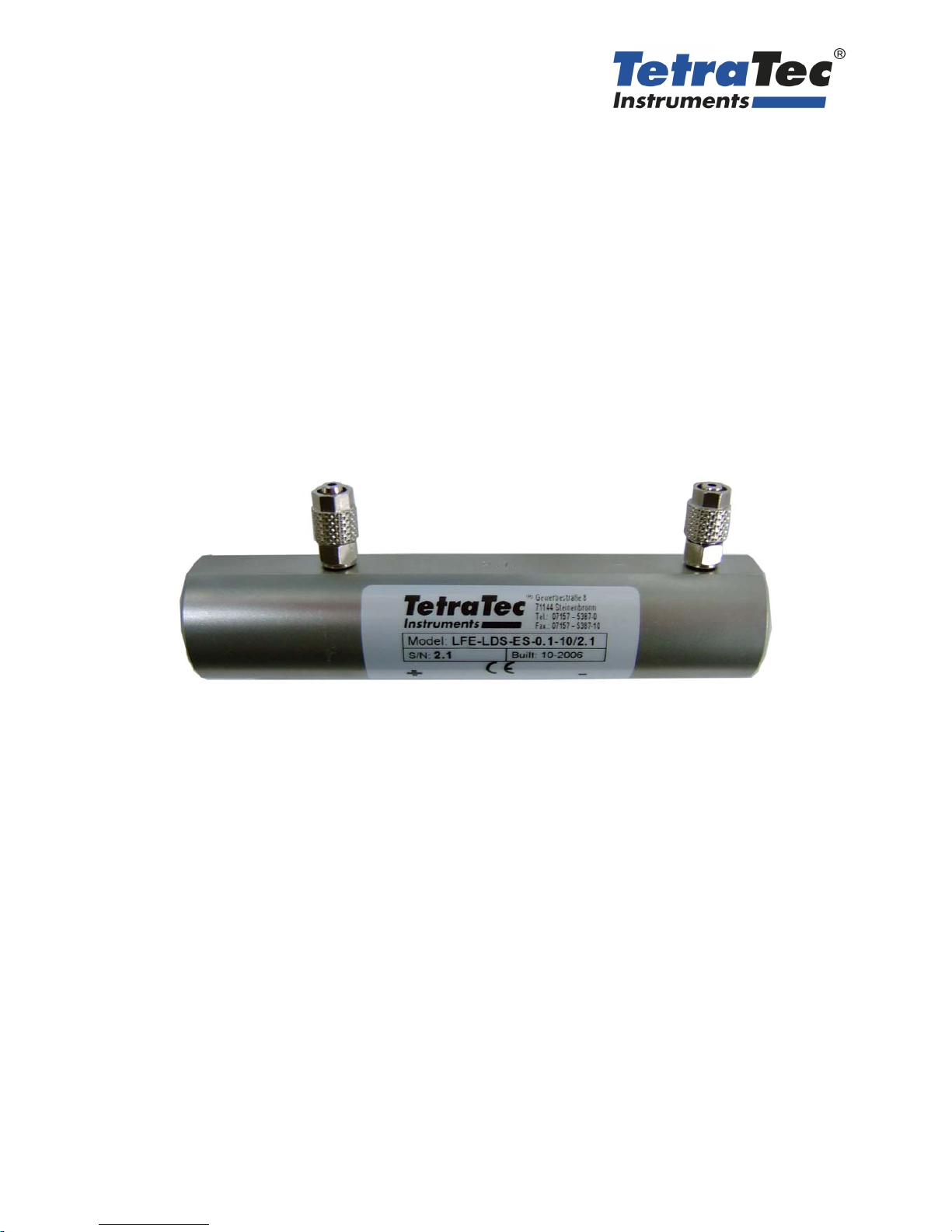
LFE-LDS
Flow Element
*** VERSION 2.0 ***
Update: 30.03.2012
Manual
LFE-LDS
page 2 LFE-LDS_man_e.doc
GENERAL HINTS
Typographical Conventions
MEANS OF DISPLAY
marks a work procedure, which you must implement
references marks which you should not neglect otherwise your health or the
operability of the equipment is endangered
marks important additional information, hints and recommendations
referring to precautionary measures mark during the handling of electrostati-
cally unloading-endangered elements or modules.
TYPES OF DISPLAY
Menu Items
Texts of screen displays were shown in cursive letter
(e.g.: End Program).
Predefined Parameter
Parameter which are set at the delivery of the unit as factory settings were underlined. (i.e.:
0 ... 9999)
SAFTEY HINTS
Please consider the references of this manual as well as the operating conditions and per-
missible data, which are specified in the data sheets of the device, so that the equipment
functions perfectly and for a long time remains operational:
Adhere with operational planning and the enterprise of the equipment to the general rules
of the technology!
Installation and maintenance work may take place only with technical personnel and with
suitable tools!
Consider the valid accident prevention and safety regulations for electrical devices during
the enterprise and maintenance of the equipment!
Switch off power supply before interferences into the system in any case!
Meet suitable measures, in order to exclude unintentional operation or inadmissible im-
pairment!
Ensure after an interruption of the electrical supply a defined and controlled restart of the
process!

Manual
LFE-LDS
LFE-LDS_man_e.doc page 3
GENERAL HINTS................................................................................................................2
INTRODUCTION .................................................................................................................4
FUNCTIONAL PRINCIPLE .................................................................................................5
OPERATION .......................................................................................................................7
MAINTENANCE ..................................................................................................................8
SPECIFICATIONS...............................................................................................................9
DIMENSIONS....................................................................................................................10

Manual
LFE-LDS
page 4 LFE-LDS_man_e.doc
INTRODUCTION
This manual describes the LFE-LDS slit type Laminar Flow Elements for all kind of different flow
channel shapes which have a full scale flow between 0,05 SL/min to 150 SL/min air. This slit type
LFE can be evaluated with any differential pressure measurement devices to determine the flow of
air and gases. The LFEs are calibrated with air at room temperature between 16 – 26°C. A simple
conversion for other gases can be made with the viscosity relation of air and the operating gas by
using the formula of Hagen-Poiseuille. The LFE-LDS measure the actual volume flow with the dif-
ferential pressure (drop) which is created by friction! The total pressure drop across the LFE is
about 1,5 to 2-times of the measured DP. The flow direction is preferred in unidirectional way, can
be principally also used in bi-directional way. The LFE-LDS are calibrated normally for atmospheric
pressure (1 bar abs.). But they can also be used in the pressure range between 0,1 – 2 bar abs..
Higher static pressures are possible respectively with a reduced DP range.
Suppliable LFE-LDS Laminar Flow Meter
Supplied can be the „LDS-ES“ type made of stainless steel, as well as „LDS-AL“ made of alumin-
ium. The series „ES“ is designed for flow rate full scales between 0,01 l/min to 5 l/min. The series
„AL“ is designed for flow rate full scales between 10 l/min und 150 l/min. The nominal differential
pressure across the LFE -LDS is as a standard for all flow rate full scales 10 mbar. It can be ex-
tended without a bigger problem to 20 mbar on request. Beside of the LFE-LDS standard model
series-we can laso supply on customer request special sizes and intermediate sizes.
Specific safety instructions for secure handling of the LFE-LDS elements
The very small size of the flow channel is quite sensible against pollution. So please ensure that
these LFE are only operated with clean dry air and gases. If the flow channel is closed partially the
characteristics will change and the original calibration may no more be valid anymore. In this case
the LFE-LDS must be cleaned and recalibrated in the factory.
Check Delivery Content
• The LFE-LDS comes along with a manual of operation and a calibration data sheet
• The LFE-LDS were supplied with closing caps on the thread connection. Dismount these and
have a look through the flow channel cross section against a bright light. There should be
none of the flow paths closed.
Installation Requirements
Ensure before mounting: connect the LFE-LDS into a pipe, tube or measurement section only if
there is no dirt or other particles inside to see. If dirt is not to exclude in operation and the section
will not stay clean for ever it is strictly recommended to use an inlet filter with a filter rate of equiva-
lent to 5µm.
The two pressure connection lines for the DP pressure transmitter should have about the same
pipe length and diameter if possible and should be absolutely tight.
The temperature sensor should have a distance of about twice of the used pipe diameter in front of
the LFE-LDS input. If an absolute pressure sensor is used it should be connected at the positive
(+ plus) pressure tap of the DP.
The LFE-LDS can be connected into the line by a thread connection. In any case please verify and
respect the flow direction of the LFE-LDS (see arrow mark). Concerning the mounting direction
there is no limitation. In general the horizontal mounting direction is preferred compared to the ver-
tical direction, because the temperature may increase with 1°C/m height.
To achieve good measurement results one have to pay attention that the free cross section close
to the process connections is reduced as little as possible. This means that the wall thickness of
threads or directly screwed pipes shouldn’t be larger than 2 mm. Is it not possible to hold this rec-
ommendation the LFE-LDS should be calibrated from the manufacturer with the actually used flow
sections. This allows the maximum possible accuracy for your application.

Manual
LFE-LDS
LFE-LDS_man_e.doc page 5
FUNCTIONAL PRINCIPLE
By flow measurement you have to differentiate between mass flow ]/[ skgqMand volume flow
]/³[ smqV. Both values correspond with the density
ρ
of the medium.
VM qq ⋅=
ρ
The laminar flow meters use the pressure drop ∆p in a laminar pipe or crack stream to designate
the volume flow V
q.
The volume flow results by the equation:
p
k
qV∆= *
η
At this is ka device specific absolute term and ηthe dynamic viscosity or durability of the gas.
Because the dynamic viscosity ηof the gases is independent of the pressure in a wide range (up
to 6 bar), it is possible to realize an almost operation pressure independent actual volume flow
measurement.
Conditions therefore are:
Stabilisation of laminar flow, means a lower and upper flow limit mustn’t overshoot. The lower limit
of sensibility is defined by the accuracy of the pressure measuring device only. By the dimension-
ing of the laminar flow meter you have to divers between the entrance region of the stream into the
flow channel and the range of the well-established laminar profile.
entrance region

Manual
LFE-LDS
page 6 LFE-LDS_man_e.doc
A linear device function can be reached only if the inlet length of the section is long enough. In the
development of the laminar flow meter it was paid high attention to eliminate all disturbing fluid
mechanical effects (starting range effects, transition e.g.). To minimize risks by pollution there are
used rectangle cracks or cylindrical ring cracks with a crack waists of 0,5 up to 1 mm.
Advantages of laminar flow meter
Laminar flow meter have no moveable parts. Thereby they are little accident-sensitive.
The temporal response behaviour of the laminar flow meter is very fast. Volume flow variations in
the range of less than 10Hz are resoluted. It is independent to the operation pressure as long as
the product
VSystem qp *
fulfills a limit value, which guarantees a laminar flow. The measuring value ∆P is proportional to the
volume flow qvin the laminar range which makes an evaluation easier. The measuring value ∆P
can be displayed with direct indicating devices, with U-pipes, Betz manometer and micro manome-
ter or with electronical differential pressure transmitter.
The resting pressure drop 1.5-2 * ∆Pis very small. The relative failure lies below one percent of
the measuring value. The resolution is dependent of the used pressure transmitter. The laminar
flow transmitter are calibrated by a ambient air temperature of 20°C. By using established gas data
it is easily possible to convert the calibration factor to other gases and other temperatures. For the
calculation of the mass flow rate qMonly the gas density ρis needed (continuity law).
Ideal laminar elements measure the volume flow qvindependent on gas density ρ.
The measuring value ∆Pis dependent in the laminar range only to the dynamic viscosity of the
medium. For controlling a process the type of flow measurement should be configured to the spe-
cific circumstances. The following table shows the primary measuring dimensions of different flow
meter and the dependence of the measuring dimensions of flow and gas characteristics.
Flow Meter Primary dimension
Volumetric meter Frequency ~V
q
Laminar pipe p∆~ ηV
q
Thermical mass flow meter
T
∆Vp qc
η
~resp.
qcp
~
Venturi flow meter p∆~ ρV
q²
Norm orifice p∆~ ρV
q²
At volumetric laminar pipes it counts the primary measuring dimension
V
qp
η
~∆
whereas ηis the dynamic viscosity of the medium and V
qis the volume flow.
At thermical mass flow meter it counts:
pM cqT ~∆
whereas cp is the specific heat and qMis the mass flow.
For venturi flow meter and norm orifices counts:
²~ V
qp
ρ
∆
According to this the characteristic curve is in qvquadratic. For the determination of qvadditionally
the gas density have to be established.
Manual
LFE-LDS
LFE-LDS_man_e.doc page 7
OPERATION
Procedure:
• Put at first the line into operation.
• Measure the differential pressure at the DP-pressure taps.
• Measure the gas temperature and if required the humidity of the flowing air.
• For the accurate evaluation of the volume or mass flow one has to measure also the static ab-
solute pressure in the line to calculate the density and also the viscosity of the flowing gas cor-
rectly.
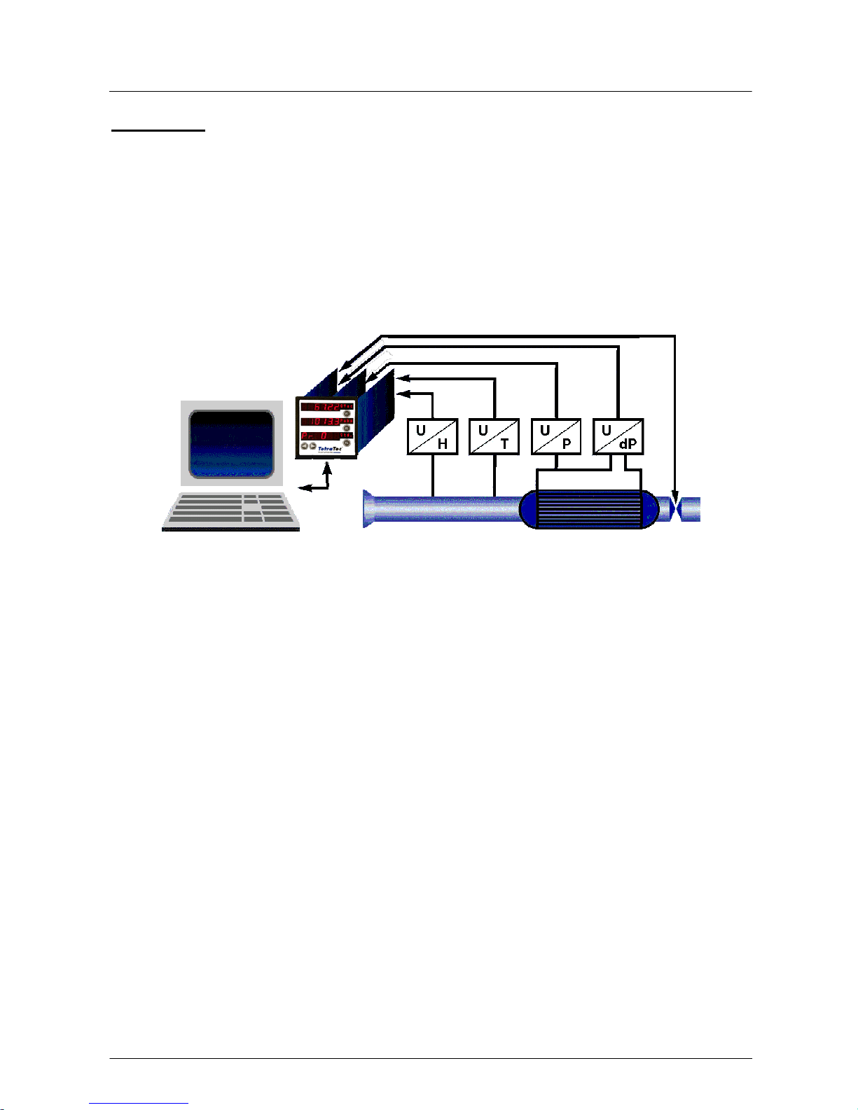
• With all of these measured sensor data later the evaluation can be done. The flow can be cal-
culated manually or by using a flow computer what does do this calculation online.
Typical Sensors for Evaluation
H = rel. humidity / T = temperature / P = absolute pressure / dP = differential pressure
Calibration curves /- tables
Each LFE-LDS is calibrated against a "calibration master device" which is traceable to the PTB
(the highest german calibration institute). As a standard the LFE-LDS is calibrated with dry clean
air and the calibration results will be converted and corrected on standard calibration conditions of
21,1°C, 1013,25 mbar abs. and 0% rel. humidity.
Every LFE-LDS comes with an own calibration certificate. For this purpose at the order should be
defined the measurement units of the customer at least if they should be different than our stan-
dard. Based on the calibration data the actual flow rate Q can be calculated:
Q = (B x dP + C x dP2) x F = Qcal x F
B, C = calibration coefficients; shown for every LFE-LDS in the calibration certificate
F = viscosity correction factor = calibration viscosity / actual viscosity
Qcal = volume flow at calibration condition
Please confirm that you are using the right calibration certificate for the LFE. (Compare the serial
number).
Calculating the Flow
With the formulas, tables and diagrams shown in the calibration certificate the volume flow can be
calculated.
Air Flow Measurement
Procedure:
• Read the differential pressure.
• Use the formula to calculate the flow:
Qcal = B x dP x + C x dP2
The resulting calibration volume flow must be corrected with the viscosity factor to achieve the
actual volume flow and this again has to be multiplied with the density to receive the mass flow
Manual
LFE-LDS
page 8 LFE-LDS_man_e.doc
Gas Flow Measurement (other gases than air)
The same procedure as described above can be applied in principal for any other Gas than air. But
the actual volume flow must be calculated with the viscosity factor, the actual viscosity of the actual
gas as well as the density of the used media must be used for the calculation of the mass flow.
This procedure is only valid if the LFE-LDS is operated within the same Reynolds number range as
found in the calibration!
MAINTENANCE
Because the LFE-LDS has no moving parts it is almost free of service. But it is recommended to
clean the LFE-LDS in regular periods of 3 to 5 years and shelter it also by a suitable filtration (bet-
ter 5 µm) of the flowing media against bringing in dust and dirt into the slit.
Cleaning
Procedure:
• Take the LFE-LDS out of the line
• Inspect the slits for mechanical damages and on closing dirt of the flow paths
• Try to blow out the LFE-LDS with clean and oil free compressed air against the recommended
flow direction.
• If you find oily or gluing dirt on the LFE-LDS it may only be cleaned with proper and completely
in water resolving cleaning means which don’t build sedimentation. Please contact our com-
pany for accepted cleaning fluids, because not acceptable cleaning fluids can lead to damages
of the LFE.
For maintenance and repair we offer a special cleaning and recalibration
service.
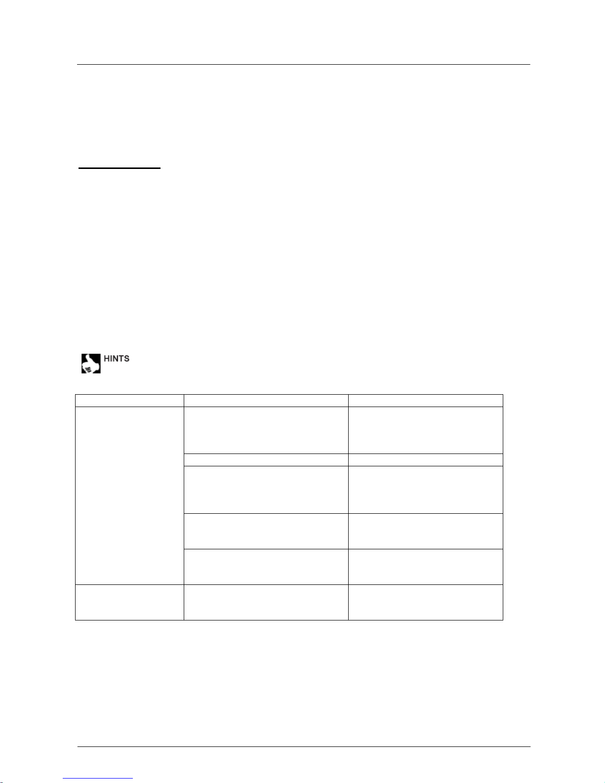
Search and solving problems
Problem Possible cause Solving problem
Recommended straight in- and
outlet sections not present Straight inlet section 10 x D
Straight outlet section 5 x D
i.e.: D = 100 mm
inlet 1 m, outlet section 0,5 m
LFE-LDS slit polluted Clear or change LFE
Line and DP connecting tubes
could be bended to narrow so that
flow and pressure measurement
cannot work properly
Control line and DP connection
tubes for straight and reason-
able bending and correct that if
that solves the error.
DP connecting tubes have a dif-
ferent length and / or diameter or
are laid out in different positions
Correct that if that solves the
error
Display shows unreal-
istic
differential pressure or
wrong flow value
Reducers are directly at the in-
/outlet into the LFE-LDS and are
limiting the flow.
Use an appropriate connection
diameter.
differential pressure is
pulsating Turbulent flow profile in the LFE-
LDS or leakage Leak in DP con-
necting tubes.
Lower static pressure or lower
flow, tightening of the leakage.
Manual
LFE-LDS
LFE-LDS_man_e.doc page 9
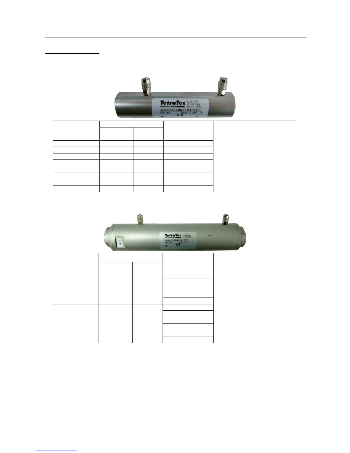
SPECIFICATIONS Serie ES
qvType
LDS-ES- [l/min] [m³/h] DP ∆p [mbar]
0.01 10 0.6 10
0.025 25 1.5 10
0.05-10 50 3 10
0.1-10 100 6 10
0.25-10 250 15 10
0.5-10 500 30 10
1-10 1000 60 10
2.5-10 2500 150 10
5-10 5000 300 10
Measuring range final values:
0 – nominal volume flow
The resolution is defined by the
used pressure transmitter.
Serie AL
qv
Type
LDS-AL- [l/min] [m³/h] DP ∆p [mbar]
10
10 10 0.6 5
25 25 1.5 10
5
50 50 3 10
5
75 75 4.5 10
5
125 125 7.5 10
10
150 150 9 10
Measuring range final values:
0 – nominal volume flow
The resolution is defined by the
used pressure transmitter.

Manual
LFE-LDS
page 10 LFE-LDS_man_e.doc
DIMENSIONS
Serie ES
LDS-ES-0.01-10 up to LDS-ES-1-10
weight: 480 g
LDS-ES-2.5-10
weight: 630 g
LDS-ES-5-10
weight: 690 g

Manual
LFE-LDS
LFE-LDS_man_e.doc page 11
Serie Al
LDS-AL-10-10 up to LDS-AL-25-10
LDS-AL-50-10 up to LDS-AL-150-10
Table of contents


