NARIKA C15-1008-W0 User manual

1
C15
C15C15
C15-
--
-1
11
1008
008008
008-
--
-W0
W0W0
W0
Lever
LeverLever
Lever & Pendulum S
& Pendulum S & Pendulum S
& Pendulum Set
etet
et
KGF
KGFKGF
KGF
Instruction Manua
Instruction ManuaInstruction Manua
Instruction Manual
ll
l
arika Corporation
arika Corporationarika Corporation
arika Corporation
201
201201
2014
44
4
Edition
EditionEdition
Edition
Thank you
Thank youThank you
Thank you very much
very much very much
very much for purchasing
for purchasing for purchasing
for purchasing
Lever
LeverLever
Lever & Pendulum set
& Pendulum set & Pendulum set
& Pendulum set.
..
.
Read all these instructions before use.
Read all these instructions before use.Read all these instructions before use.
Read all these instructions before use.
The Lever & Pendulum set is special
The Lever & Pendulum set is specialThe Lever & Pendulum set is special
The Lever & Pendulum set is specialy
yy
y designed for student experiment
designed for student experiment designed for student experiment
designed for student experiments
ss
s in school
in school in school
in school.
..
.

2
Introduction
IntroductionIntroduction
Introduction
This lever & pendulum set is for students’ experimentation including a lever unit, a pendulum
unit, weights, and a steel stand. For easier experimentation by students, the lever unit has
numbered holes on it to hook weights, while the pendulum unit has a semicircular protractor for
measuring angle of pendulum, as well as, an adjusting knob to adjust the length of thread. In
addition, the lever & pendulum set pays much attention to the storage in schools. Lever unit has a
function to be fixed vertically on the steel stand, while pendulum unit has a function to reel a
thread of itself, requiring less space for the storage. With the lever unit, students’ group may carry
out the experimentation for “Motion of Force” such as the correlation between fulcrum point and
point of effort/load or moment of force. With the pendulum unit, students' group may carry out
experimentation for “Pendulum motion” such as correlation between the length of thread with
weight and the cycle, as well as, energy conversion of potential/kinetic energy.
Safety Precautions (
Safety Precautions (Safety Precautions (
Safety Precautions (r
rr
read before use)
ead before use)ead before use)
ead before use)
otice
oticeotice
otice
1.
1. 1.
1. Make sure
Make sureMake sure
Make sure knobs o
knobs o knobs o
knobs on
nn
n lever
lever lever
lever unit
unit unit
unit and pendulu
and penduluand pendulu
and pendulum
m m
m unit (depending
unit (depending unit (depending
unit (depending on
on on
on which unit you
which unit you which unit you
which unit you
use)
use) use)
use) at the
at the at the
at the pole
polepole
pole of stand
of stand of stand
of stand are securely tightened.
are securely tightened. are securely tightened.
are securely tightened.
2.
2. 2.
2. F
FF
Fix the base and
ix the base and ix the base and
ix the base and the pole of stand.
the pole of stand.the pole of stand.
the pole of stand.
Contents
ContentsContents
Contents
1. Lever unit
1. Lever unit1. Lever unit
1. Lever unit
*Arm (Lever): 1
*Lever holder: 1
2. Pendulum unit
2. Pendulum unit2. Pendulum unit
2. Pendulum unit
*Protractor: 1
*Thread: 1
3. Steel stand
3. Steel stand3. Steel stand
3. Steel stand
*Pole rod: 1
*Base: 1
4.
4. 4.
4. Weight
WeightWeight
Weight
*13 pcs

3
Specification
SpecificationSpecification
Specification
For
For For
For “
““
“Lever Mode
Lever ModeLever Mode
Lever Mode”
””
” ( Lever Apparatus )
( Lever Apparatus ) ( Lever Apparatus )
( Lever Apparatus )
1
11
1. Pole rod
. Pole rod. Pole rod
. Pole rod
*Material: Brass and nickel chrome plate,
*Size: φ12×ca 440mm
2
22
2. Base
. Base. Base
. Base
*Material: Steel,
*Size: 180×140×15mm,
*Weight: ca 480g
3
33
3.
. .
. Lever
LeverLever
Lever
*Material: Aluminum,
*Size: 30 x 400mm,
*12 scale marks (30mm space) with printed numbers 1~6 on both
side of the lever.
*12 holes on upper and lower edge of the lever, total 24 holes.
4. Lever holder
4. Lever holder4. Lever holder
4. Lever holder
*Size:ca55×50×35mm,
*Weight: ca 80g
For
For For
For “
““
“Pendulum Mode
Pendulum ModePendulum Mode
Pendulum Mode”
””
” ( Pendulum Apparatus )
( Pendulum Apparatus ) ( Pendulum Apparatus )
( Pendulum Apparatus )
1. Pole rod
1. Pole rod1. Pole rod
1. Pole rod
*same as before
2. Base
2. Base2. Base
2. Base
*same as before
3
33
3. Protractor plate
. Protractor plate. Protractor plate
. Protractor plate
* Diameter 100mm, Semi-circular, Max.120 degrees (10 degrees
step)
4
44
4. String adjustment knob
. String adjustment knob. String adjustment knob
. String adjustment knob
*String reeling
5
55
5. Screw
. Screw. Screw
. Screw
*M4 x 8mm
6
66
6.
. .
. Thread
ThreadThread
Thread
*To be suspended in V-shape. Length: Max.1m.

4
Preparation (Assembling)
Preparation (Assembling)Preparation (Assembling)
Preparation (Assembling)
1. Assembl
1. Assembl1. Assembl
1. Assembling
inging
ing S
S S
Stand
tandtand
tand
1. Remove the nut and washer from the pole
at once.
2. Install the pole into the hole in the base.
3. Tighten the pole by the washer and the nut
using tools.
4. Before experiment, check that the screw is
tightened enough.
2. Set
2. Set2. Set
2. Setting
tingting
ting
up
up up
up Lever
LeverLever
Lever
1. Insert the pole rod into lever holder.
2. Tighten the screw of the lever holder.
3. Set
3. Set3. Set
3. Setting
tingting
ting
up
up up
up Pendulum
PendulumPendulum
Pendulum
1. Loose its screw and turn the protractor plate of the pendulum unit to be mounted orthogonally
on its rod (see step1).
2. Tighten the screw on the rod at the orthogonal position of the protractor plate and the rod (see
step2).
3. Protractor plate should be fixed by the screw (see step 3).
4. Loose the screw at the end of the rod and insert the top of pole (see step 4).
5. Tighten the screw at a suitable position (height) for the pendulum experiment (see step 5).
Step 1 Step 2 Step 3 Step 4 Step 5
6. Pull out a string while turning the string
adjustment knob anticlockwise by your
fingers (see step 6).
7. Hook a weight on the string.
8. Adjust the string to suitable length for the
experiment by turning the string adjustment
knob clockwise or anticlockwise (see step 7).
Step 6 Step 7

5
Caution of Pendulum Apparatus during the experiment
Caution of Pendulum Apparatus during the experimentCaution of Pendulum Apparatus during the experiment
Caution of Pendulum Apparatus during the experiment
1. Position of weights
If the weights are hooked like in Fig.1, they may cause errors in the experiment. When using
several weights in the experiment, hook them like in Fig.2 in order to align the center of weights
(see Fig.1 & 2).
2. Length of Pendulum (thread length)
Common mistake in measuring the length of pendulum is: measuring the length from the bottom
vertex of a triangle, where weight is hooked (V shape) to the bottom surface of the rod (see
Fig.3). The correct length of pendulum is from the center of weight to the bottom surface of the
rod – red line (see Fig. 4). You should use the vertical line distance in Fig.4 as the correct length
of pendulum.
[ Fig.1 ] [ Fig. 2 ] [ Fig. 3 ] [ Fig. 4 ]
C
CC
Complete
ompleteomplete
ompleted
dd
d Apparatus
Apparatus Apparatus
Apparatus
Lever mode Pendulum mode

6
Stor
StorStor
Storing App
ing Apping App
ing Apparatus
aratusaratus
aratus
Storing
StoringStoring
Storing
Lever
LeverLever
Lever Apparatus
Apparatus Apparatus
Apparatus
The lever apparatus is not suitable for storage, because lever is too long to usually fit into a cabinet
of a science room. You can save space and store many lever apparatuses in a cabinet, since the
lever apparatus has a storage mode for easier storage.
1. Pull the knob in the center of lever (see step 1).
2. Turn the lever pulling (see step 2).
3. Move the lever to vertical position and push the knob to hold it (see step3).
Step 1 Step 2 Step 3
Storing Pendulum Apparatus
Storing Pendulum ApparatusStoring Pendulum Apparatus
Storing Pendulum Apparatus
The pendulum apparatus (unit) has storage mode such as the lever apparatus.
1. Pull the pendulum unit out from the pole rod (see step 1, 2, 3).
2. Turn the Protractor plate to vertical position (see step 4, 5).
Step 1 Step 2 Step 3 Step 4 Step 5
Maintenance
MaintenanceMaintenance
Maintenance of Pendulum
of Pendulum of Pendulum
of Pendulum
When you should exchange a thread of pendulum to new one, follow steps below.
1. Remove existing string from the pendulum unit.
2. Insert a new string into 2 holes, one edge on the top of the pendulum unit and the other edge on
the string adjustment knob (see step 1 and step 2).
3. Tie both ends of the string (see step 3).
4. Move the tied knot into the hole of the string adjustment knob (see step 4).
Step 1 Step 2 Step 3 Step 4

7
Sample of Experiment
Sample of ExperimentSample of Experiment
Sample of Experiment
Experiment 1 (Lever Apparatus
Experiment 1 (Lever ApparatusExperiment 1 (Lever Apparatus
Experiment 1 (Lever Apparatus)
))
)
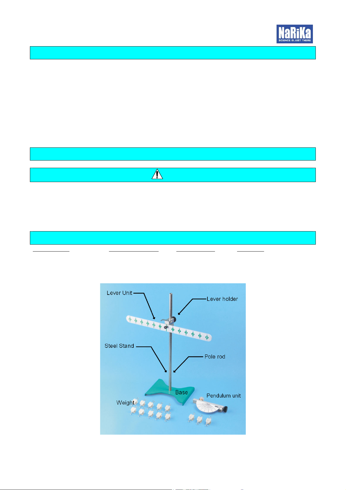
Lever Apparatus is designed for a student experiments regarding moment (of force) – torque in the
lever balance. Moment of force is the product of the distance of mass from the fulcrum point and
the weight.
[ Weight ] x [ Distance from the fulcrum point ] = Moment of force
Therefore when an anticlockwise moment equals a clockwise moment of the lever, the lever can
keep its balance horizontally.
Moment (anticlockwise) = Moment (clockwise)
Let’s set weight unit as 1w and set distance unit
as 1a.
In Fig.1, the right side of the lever has a weight
at position 4. Its moment of force is:
[Moment(clockwise)] = 4a x 1w = 4aw
The left side of the lever has 4 weights at position
1. Its moment is:
[Moment(anticlockwise)] = 1a x 4w = 4aw.
Therefore:
[Moment (clockwise)] = [ Moment (anticlockwise)]
[ Fig.1 ]
[ Fig.2 ]
In Fig.2, the right side of the lever has 3
weights at position 1, 1 weight at position 2,
and 2 weights at position 3. Its moment of
force is:
[Moment(clockwise)] = (1a x 3w) + (2a x 1w) +
(3a x 2w) = 3aw + 2aw + 6aw = 11aw
The left side of the lever has 1 weight at
position 2, 1 weight at position 3, and 1 weight
at position 6. Its moment of force is:
[Moment(anticlockwise)] = (2a x 1w) + (3a x
1w) + (6a x 1w) = 2aw + 3aw + 6aw = 11aw.
Therefore:
[Moment (clockwise)] =
[ Moment (anticlockwise)]

8
Experiment 2 ( Pendulum
Experiment 2 ( PendulumExperiment 2 ( Pendulum
Experiment 2 ( Pendulum Apparatus )
Apparatus ) Apparatus )
Apparatus )
The period of the pendulum for student experiment.
1. Preparation
Teacher should prepare the pendulum apparatus and a stopwatch, and a ruler for this student
experiment.
2. Procedure
1) Set the thread length of pendulum about 20 cm by using the ruler.
2) Hook a weight (10g) on the string.
3) Lift the weight up to the angle of string θ (amplitude) = 8 ~ 10 degrees.
4) Measure the time by a stopwatch during 10 periods of back and forth motion.
5) Fill out result on the datasheet.
6) Change conditions of experiment, such as: add weights, change length of the string pendulum
(to 25, 30 cm etc.) and make the experiment again and again to see the different results.
3. Result
Length(cm) Weight(g) Total Time(s) Time/10(s)
1)_________ ______ ________ _______
2)_________ ______ ________ _______
3)_________ ______ ________ _______
4)_________ ______ ________ _______
5)_________ ______ ________ _______
*”Time/10” is “Total Time” divided by 10 (the amount of
periods).
The pendulum’s period is shown as below:
*T is period, L is length of pendulum, g is gravitational
acceleration. The equation is for teacher.
arika Corporation
arika Corporationarika Corporation
arika Corporation
3-10, Soto-kanda 5-chome, Chiyoda-ku, Tokyo 101-0021
Phone: +81-3-3833-0741, e-mail:global@rika.com
URL http://global.narika.jp
Table of contents
Other NARIKA Industrial Equipment manuals
Popular Industrial Equipment manuals by other brands

Des Champs Technologies
Des Champs Technologies HVAC Air-Trap P Series Installation, operation and maintenance manual

Petol
Petol Hydra-Tork U8184 operating manual

FRIEND
FRIEND FW-6610A product manual

HBM
HBM MP55DP operating manual

Delta Electronics
Delta Electronics HEX060PA instruction manual

Wilo
Wilo Wilo-EMU FA+T-Motor Installation and operating instruction