SMW Ku-band User manual

Ku-band
Dual system
USER GUIDE
Please read and un-
derstand the contents
of this USER GUIDE
before attempting to
connect or use the
system!

CAUTION!
BDCs and splitters shall be mounted close to
the antenna or at back side of antenna though
delivered cables are calibrated with the system
and shall not be exchanged to any other cables.
If other cable length are wanted you must
contact SMW for consultation!
1. Description
SMW Ku-band Dual system is a system including Ku-
band LNA, cables and BDCs to cover the frequency
range 10.70 to 12.75 GHz or by request.
Thanks to using high quality cables between LNA,
splitters and BDCs, it’s possible to achieve high perfor-
mance for simultaneously reception of the frequency
band between 10.70 and 12.75 GHz. The system can be
offered in different frequency bands for BDCs to comply
to your needs.
All components are high quality weather proof with an
temperature range of -40 to +80 degree Celsius. Con-
nectors are SMA except output connectors for the BDCs
that can be ordered as SMA, N or F connectors.
BDCs can be delivered with internal or external 10 MHz
reference oscillator.
For full specication, please see our specication
datasheet.
WARNING!
Only power LNA and BDCs with +12 to
+24 VDC.
There are no customer serviceable parts
inside, refer service to the SMW factory.
3. Installation instructions
Unpacking
Please check the contents of your shipment upon receipt
towards the packing list supplied and notify us immediate-
ly if you feel that something is missing.
Contents:
1. Description
2. Safety
3. Installation instructions
4. Troubleshooting
Mounting
The system components are weatherproofed and designed
for operation in temperatures between -40 and +80 C
They can normally be mounted outdoors without extra
protection.
However, for extreme environments such as close to
corrosive salt/sea water or elevated installation in antenna
towers where IP67 class protection can be deemed insuf-
cient, it is recommended that appropriate action is taken to
ensure reliable operation and longevity.
2. Safety
2

continue, Mounting.
Cables shall be mounted according to Fig. 1 regarding
cable lengths to avoid mismatch between LNA, splitters
and BDCs.
3
CAUTION!
Max. bending radius of cables between LNA,
splitters and BDCs are 50mm. If cables are
bent more, this will decrease the performance
of the system.
Max. torque of the SMA connectors is 1 Nm.
LNA, DC cable
connection.
3.8 meters DC cable for
feed of DC from BDC to
the LNA.
NOTE! Other DC cable length
can be delivered by request.
Fig. 1
Example:
A- Frequency 10.70 - 11.70 GHz, LO 9.75 GHz
B - Frequency 11.70 - 12.75 GHz, LO 10.60 GHz
See Fig. 1 and Fig. 2 at next page.
AA
B
3.0 meters
calibrated
HF cables.

4
Fig. 2

Application assistance
Your rst line of technical support would to take advanta-
ge of SMWs long experience. Please feel free to contact
us at an early stage for free advise on your application
before you place an order. You’ll nd our contact details
on the back of this User Guide. We welcome your enqui-
ries.
Testing
When all cables and connectors are correctly installed,
you can run an RF / L-band testsignal through the system
to verify correct operation.
Troubleshooting
If the output L-band signal is not meeting the calculated
specication, rst thing to check is the HF cables and
connectors.
- Make sure that bend radius is not less than the min.
recommended.
- Check that all connectors are tigthened correct accor-
ding to max. torque (1Nm).
There is no micro processor or software inside the units.
There are no user serviceable parts or fuses inside.
5
Service
There are no user serviceable parts inside.
Spare parts as LNA, BDC an HF cables can be ordered
separately. Please, include serial number(s) of the
original part with any spare part request.
For factory service, contact SMW for an RMA number
before returning any material.
Material returned without an RMA number will be refused.
Standard warranty is 36 months.

Technical specification
The Dual PLL is the professional solution to receive the
two bands simultaneously with high LO stability and low
phase noise.
Any LO frequencies can be combined without
spuriouses e.g. Low band 10.0 GHz & High band
11. 3 G Hz .
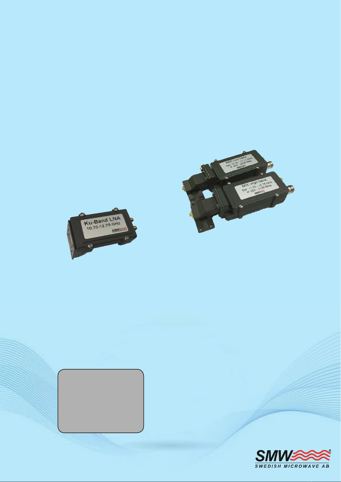
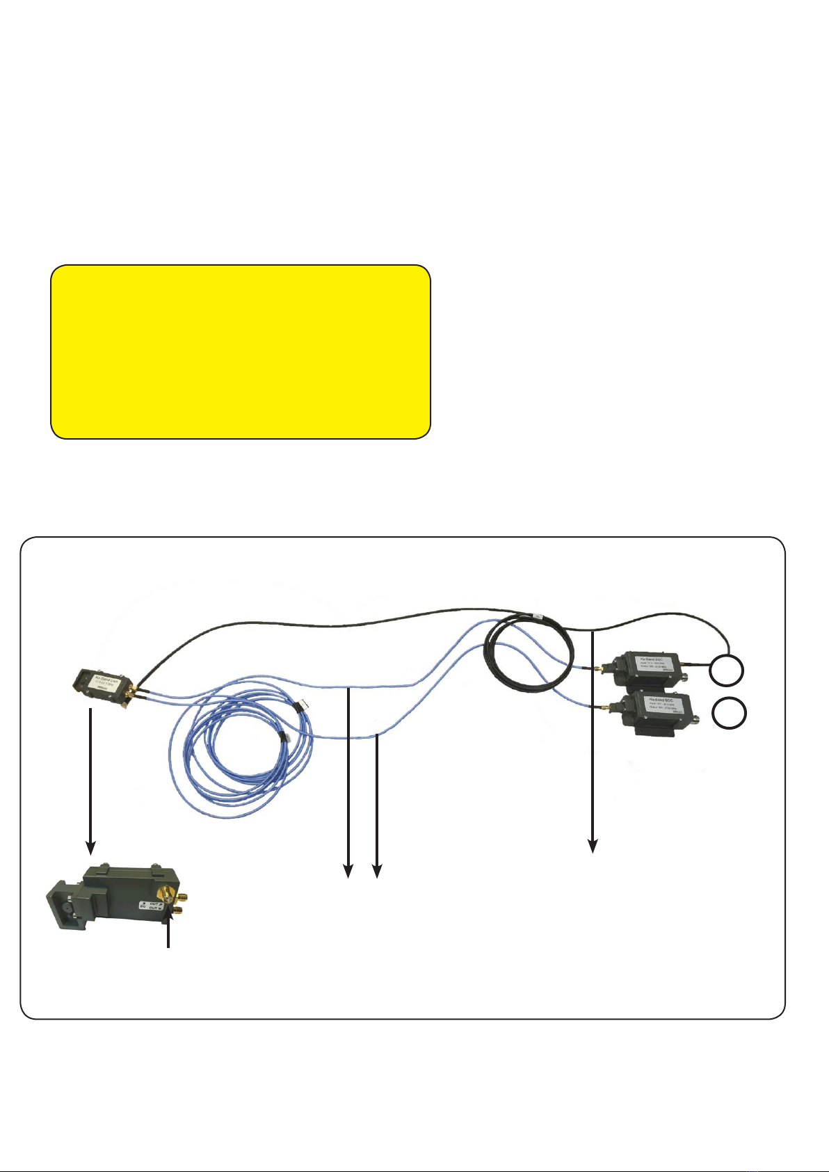
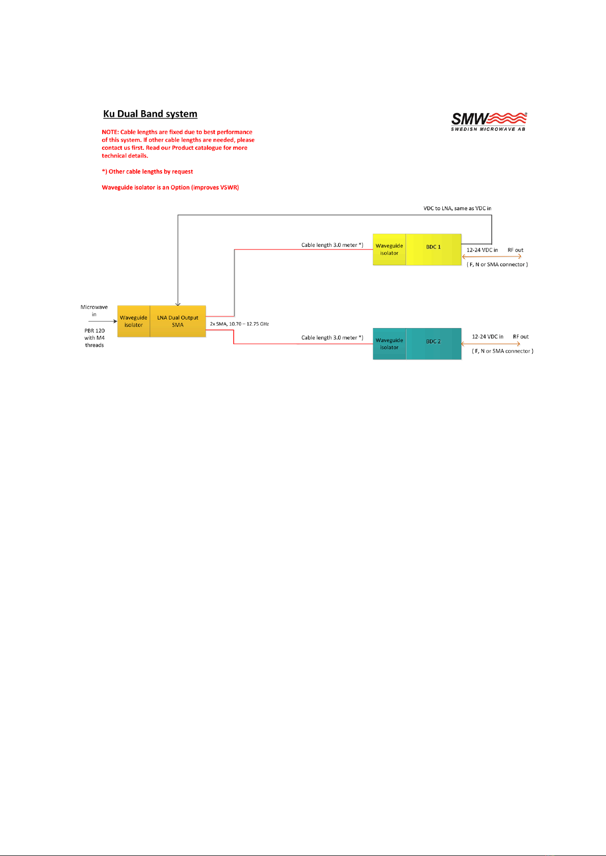
The standard solution consists of one LNA and two Block
Down converters including RF and DC cables 3-6 m. All
parts are optimized, adjusted and tested as a complete
matched unit.
Features
• Wide frequency range
• Choose between Internal Ref. or
External Ref. input models
• Several LO frequencies
• Low phase noise
• High P1dB and IP3
• Wide operating temperature range
• BDC’s for outdoor use
• Option Low prole to t 1U for build-in
applications
LNA / PLL BDC system for
simultaneous reception
of Low & High Ku-Band
LO LOW 9.75 *) 10.00**) 10.25 10.50 10.60 10.75
LO HIGH 10.60*) 10.75**) 11. 2 0 11. 2 5 11. 3 0
Input Frequency 10 .70 –11. 8 0
GHz
10.95–11.80
GHz
11. 20 –11. 70
GHz
11.45 –12.20
GHz
11.70–12.75
GHz
11.70–12.75
GHz
11.70–12.75
GHz
11.70–12.75
GHz
12. 20 –12.75
GHz
12. 20 –12.75
GHz
12. 25–12.75
GHz
LO Frequency 9.75 GHz 10.00 GHz 10.25 GHz 10.50 GHz 10.60 GHz 10.75 GHz 10.60 GHz 10.75 GHz 11. 20 GHz 11. 25 GHz 11. 30 GHz
Output Frequency 950–2050
MHz
950–1800
MHz
950–1450
MHz
950–1700
MHz
1100–2150
MHz
950–2000
MHz
1100–2150
MHz
950–2000
MHz
1000–1550
MHz
950–1500
MHz
950–1450
MHz
Gain 60 dB typ.
Flatness ±0.4 dB max. within 30 MHz ±3 dB max. over band
Noise Figure / Noise
Temperature 1.0 dB / 75 K typ.
Phase Noise -35 dBc @ 10 Hz -62 dBc @ 100 Hz -75 dBc @ 1 kHz -83 dBc @ 10 kHz -93 dBc @ 100 kHz -120 dBc @ >1MHz typ.
Spurious Signals -60 dBm typ. at the rst spurious (e.g. 1000 MHz with LO 9.75 & 10.75 GHz)
Image Rejection 40 dB min.
Output P1dB +15 dBm typ.
Output IP3 +25 dBm typ.
Output VSWR BDC 2.0:1 typ.
Output Conn. LNA SMA-connectors 50Ω
Output Conn. BDC F-type 75Ω / N-type 50Ω / SMA-type 50Ω
Input Waveguide LNA WR 75 / R 120. Flange 120.
Input Conn. BDC SMA-connector 50Ω
Input VSWR LNA 2.3:1 typ.
LO Leakage -60 dBm @ waveguide input
Internal Ref. Stability ±5 kHz -20 to +70ºC (±10 kHz -40 to +80ºC) ±10 kHz -20 to +70ºC (±15 kHz -40 to +80ºC)
External 10 MHz Ref. Level: -15 to +5 dBm. Input via output connector (with no ext. 10 MHz ref. present LO shifts -20 ppm)
DC Input LNA +12 to +24 V, 40 mA typ. Input through separate SMA connector. DC feed from low band BDC
DC Input BDC +12 to +24 V, 270 mA typ. Supplied through output connector
Temperature Range -40 to +80 °C
Dimensions LNA: 81 x 40 40 mm BDC: 142 x 99 x 70 mm (F-connector), 148 x 99 x 70 mm (N-connector) ( for drawing, see www.smw.se )
Weight LNA: 124 g BDC: 329 g (F-connector), 345 g (N-connector)
Miscellaneous Enclosed O-ring, mounting screws (M4 x 10) 4 pcs. DC cable and HF cables
Options Customized LO freq., Gain, Variation, Input and Output frequency ranges, Separate DC input connector F-, N- or SMA-type,
Cable lengths, Dierent HF cables, Waveguide isolators, Low prole to t 1U.
*) For this combination we recommend our WDL PLL LNB type E. **) For this combination we recommend our WDL PLL LNB type B.

SWEDISH MICROWAVE AB
Dynamovägen 5
S-59161 Motala
SWEDEN
Phone: +46 141 216135
info@smw.se
www.smw.se SMW DLNBDKU, Rev. 04 (C) 2018-12
Specications are subject to change without notice.
General Terms: Orgalime S 2012. Products from Swedish Microwave AB are made for commercial use unless otherwise specied.
Table of contents
Popular Industrial Equipment manuals by other brands

Afag
Afag GE-25-P Assembly and operating instructions

Electrostatic Technology
Electrostatic Technology 802 manual

Dustcontrol
Dustcontrol TPR 50 Original instructions

Baumer
Baumer hhs ULT 400 XL Operation manual

Mecc Alte spa
Mecc Alte spa TR1 Series Use and maintenance manual

Siemens
Siemens SIMATIC Ident Compact operating instructions