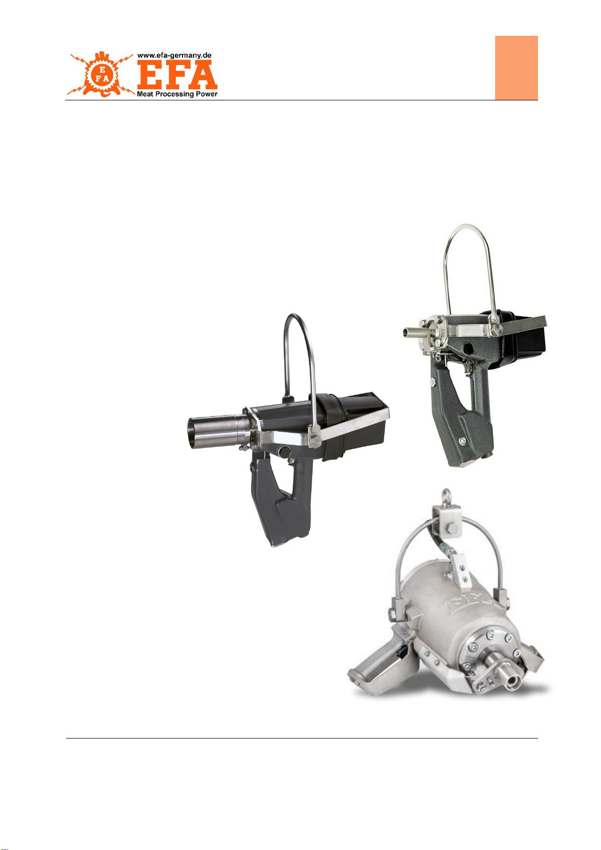
EFA stunning device Original operating instructions EN
1.4.1 Residual hazards
As the stunning device is intended for industrial use on carcasses, there is a possibility of injury or, in case of
gross misuse, of fatal injury. Therefore, in case of misuse, the possibility of immediate death or death by blood
loss must be expected.
Consequently, always pay attention to the correct handling of the machine.
1.5 Claims for defects, liability, warranty
Warranty and liability claims for personal injury and damage to property are excluded in particular in the
following cases:
Improper use or unsuitable use,
Improper transport or storage,
Improper assembly and/or initial start-up,
Improper operation (operating errors),
Disregarding of operating instructions/company directives,
Faulty or negligent handling,
Improper maintenance/repair,
Unsuitable equipment or spare parts that are not approved by Schmid & Wezel GmbH Maschinenfabrik,
Natural wear and tear,
Improper or unprofessional rectification of defects by the customer/operating company or third parties,
Unauthorised structural changes to the machine without written permission from Schmid & Wezel GmbH,
Chemical, electrochemical or electrical influences –unless they are the responsibility of Schmid & Wezel
GmbH.
Liability
The manufacturer accepts no liability for accidents, machine damage and consequences of machine failure
resulting from failure to observe the operating instructions. In addition, the local accident prevention
regulations and general safety regulations for the area of application of the machine apply.
Limitation of liability
All technical information, data and instructions for the operation of the machine contained in the operating
instructions are up to date at the time of delivery. They are provided to the best of the manufacturer's
knowledge, taking into account previous experience and knowledge. The manufacturer reserves the right to
make technical modifications in the course of further development of the machine described in these operating
instructions. No claims can therefore be derived from the information, figures and descriptions in these
operating instructions. The manufacturer shall be liable for any errors or omissions within the scope of the
warranty obligations entered into in the contract, to the exclusion of further claims.
Claims for damages are excluded, irrespective of the legal basis on which such claims are derived. Only the
text of the original operating instructions is authoritative.
The textual and graphical representation in the operating instructions does not necessarily correspond to the
scope of supply or a spare parts order. Illustrations in these instructions are not to scale.
Technical changes
The manufacturer Schmid & Wezel GmbH reserves the right to make technical changes within the scope of
improving the usage properties and further development without prior notice.
Figures are for basic understanding and could differ from the actual design of the system.
Copyright
The manufacturer reserves the copyright to these operating instructions. These operating instructions are
intended for assembly, operating, maintenance and monitoring personnel.
Transferring the operating instructions to third parties without the written consent of the manufacturer Schmid
& Wezel GmbH is not permitted. Duplication in any kind and form –in whole or in part –as well as the use
and/or communication of the contents are not permitted without written declaration of the manufacturer.
All content, texts, drawings, pictures and other
representations are protected by copyright and are subject
to industrial property rights.
Any improper use may be punishable!