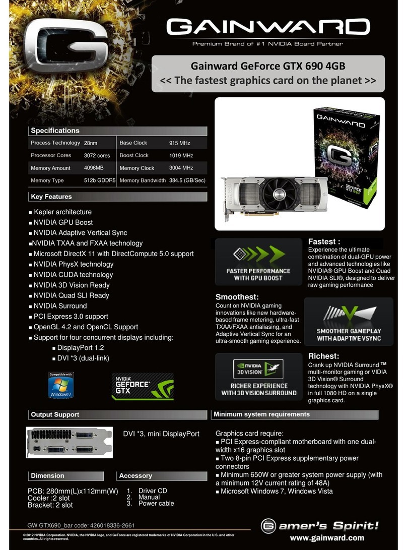
Texas Instruments TVP4020 PERMEDIA 2 User manual

Texas
Instruments
TVP4020 PERMEDIA®2
Programmer’s Reference
Manual
Issue 4

Contents TVP4020 Programmers Reference Manual
iv
IMPORTANT NOTICE
Texas Instruments (TI) reserves the right to make changes to its products or to discontinue any semiconductor
product or service without notice, and advises its customers to obtain the latest version of relevant information
to verify, before placing orders, that the information being relied on is current.
TI warrants performance of its semiconductor products and related software to the specifications applicable at
the time of sale in accordance with TI’s standard warranty. Testing and other quality control techniques are
utilized to the extent TI deems necessary to support this warranty. Specific testing of all parameters of each
device is not necessarily performed, except those mandated by government requirements.
Certain applications using semiconductor products may involve potential risks of death, personal injury, or
severe property or environmental damage (“Critical Applications”).
TI SEMICONDUCTOR PRODUCTS ARE NOT DESIGNED, INTENDED, AUTHORIZED, OR WARRANTED
TO BE SUITABLE FOR USE IN LIFE-SUPPORT APPLICATIONS, DEVICES OR SYSTEMS OR OTHER
CRITICAL APPLICATIONS.
Inclusion of TI products in such applications is understood to be fully at the risk of the customer. Use of TI
products in such applications requires the written approval of an appropriate TI officer. Questions concerning
potential risk applications should be directed to TI through a local SC sales office.
In order to minimize risks associated with the customer’s applications, adequate design and operating
safeguards should be provided by the customer to minimize inherent or procedural hazards.
TI assumes no liability for applications assistance, customer product design, software performance, or
infringement of patents or services described herein. Nor does TI warrant or represent that any license, either
express or implied, is granted under any patent right, copyright, mask work right, or other intellectual property
right of TI covering or relating to any combination, machine, or process in which such semiconductor products
or services might be or are used.
Copyright 1997, Texas Instruments Incorporated

TVP4020 Programmers Reference Manual Contents
iii
3Dlabs is the worldwide trading name of 3Dlabs Inc. Ltd.
3Dlabs, GLINT and PERMEDIA are registered trademarks of 3Dlabs Inc. Ltd.
Microsoft, Windows and Direct3D are either registered trademarks or trademarks
of Microsoft Corp. in the United States and/or other countries. OpenGL is a
registered trademark of Silicon Graphics, Inc. Macintosh and Power Macintosh
are registered trademarks and QuickDraw is a trademark of Apple Computer Inc.
All other trademarks are acknowledged and recognized.

Contents TVP4020 Programmers Reference Manual
iv
Contents
1. Introduction........................................................................................................1
1.1 How to use this manual.............................................................................................................. 1
1.2 Further Reading......................................................................................................................... 1
2. Overview ............................................................................................................2
2.1 TVP4020 Key Features.............................................................................................................. 2
2.2 Functional Overview .................................................................................................................. 3
3. Programming Model..........................................................................................6
3.1 PERMEDIA as a Register file ....................................................................................................7
3.2 PERMEDIA I/O Interface ...........................................................................................................9
3.3 Interrupts.................................................................................................................................. 20
3.4 Synchronization ....................................................................................................................... 20
3.5 Host Memory Bypass............................................................................................................... 21
3.6 DMA Controller ........................................................................................................................22
3.7 Register Read back .................................................................................................................22
3.8 Byte Swapping......................................................................................................................... 23
3.9 Red and Blue Swapping ..........................................................................................................23
4. Memory I/O and Organization.........................................................................25
4.1 Patched Data........................................................................................................................... 25
4.2 Localbuffer ............................................................................................................................... 25
4.3 Framebuffer ............................................................................................................................. 27
4.4 Double Buffering......................................................................................................................33
4.5 Texture Buffer.......................................................................................................................... 37
5. Graphics Programming...................................................................................40
5.1 The Graphics HyperPipeline....................................................................................................40
5.2 Delta Unit.................................................................................................................................42
5.3 Rasterizer Unit......................................................................................................................... 48
5.4 Scissor/Stipple Unit.................................................................................................................. 68
5.5 Localbuffer Read and Write Units............................................................................................ 73
5.6 Stencil/Depth Test Unit............................................................................................................77
5.7 Texture Address Unit............................................................................................................... 85
5.8 Texture Read Unit....................................................................................................................88
5.9 YUV Unit..................................................................................................................................95
5.10 Framebuffer Read and Write Units........................................................................................98
5.11 Color DDA Unit ....................................................................................................................105
5.12 Texture/Fog/Blend ............................................................................................................... 109
5.13 Color Format Unit................................................................................................................. 118
5.14 Logical Op Unit ....................................................................................................................121
5.15 Host Out Unit .......................................................................................................................124
6. Initialization....................................................................................................130
6.1 Initializing PERMEDIA............................................................................................................ 130
6.2 System Initialization ............................................................................................................... 130
6.3 Window Initialization............................................................................................................... 134

TVP4020 Programmers Reference Manual Contents
iii
6.4 Application Initialization ..........................................................................................................137
6.5 Bypass Initialization................................................................................................................138
7. Programming Tips.........................................................................................139
7.1 PCI Bus Issues.......................................................................................................................139
7.2 Graphics Hyperpipeline..........................................................................................................141
7.3 Area Filling Techniques..........................................................................................................142
7.4 Copies and Downloads...........................................................................................................144
7.5 Multi Buffering.........................................................................................................................145
7.6 Overlays .................................................................................................................................146
7.7 Memory Organization.............................................................................................................146
7.8 Chroma Test...........................................................................................................................147
7.9 Configuration for 2D ...............................................................................................................147
8. Delta Programming Examples......................................................................148
Appendix A. Graphics Register Reference......................................................162
Appendix B. Pseudocode Definitions..............................................................272
Appendix C. Screen Widths Table....................................................................274
Appendix D. A Gouraud Shaded Triangle without using the Delta Unit ......276
Appendix E. Register Tables ............................................................................284
Appendix F. TVP4010 and TVP4020 Differences.............................................294
Glossary .............................................................................................................300
Index ...................................................................................................................306

Contents TVP4020 Programmers Reference Manual
iv
Table of Figures
Figure 2.1 External Interfaces ............................................................................................................. 3
Figure 3.1 DMA Tag Description Format.......................................................................................... 13
Figure 3.2 Indexed Format............................................................................................................... 15
Figure 5.1 Hyperpipeline .................................................................................................................. 41
Figure 5.2 Triangle Mesh................................................................................................................... 43
Figure 5.3 Triangle Fan.....................................................................................................................43
Figure 5.4 Rasterizing a triangle........................................................................................................ 49
Figure 5.5 Polyline............................................................................................................................. 51
Figure 5.6 Relationship between Bitmask and Scanning Directions.................................................55
Figure 5.7 Copy Operation................................................................................................................ 58
Figure 5.8 Real Coordinate Representation...................................................................................... 61
Figure 5.9 Screen Scissor and User Scissor Tests........................................................................... 69
Figure 5.10 Scissor Mode Register................................................................................................... 70
Figure 5.11 AreaStippleMode Register ............................................................................................. 70
Figure 5.12 LBReadMode Register................................................................................................... 75
Figure 5.13 LBWriteMode Register ................................................................................................... 75
Figure 5.14 LBReadFormat / LBWriteFormat Register ..................................................................... 76
Figure 5.15 Depth Interpolation......................................................................................................... 80
Figure 5.16 Depth Derivative Format ................................................................................................ 81
Figure 5.17 StencilMode Register ..................................................................................................... 81
Figure 5.18 StencilData Register....................................................................................................... 81
Figure 5.19 DepthMode Register ......................................................................................................82
Figure 5.20 Window Register............................................................................................................82
Figure 5.21 Texture Address Interpolation........................................................................................ 85
Figure 5.22 Fixed Point S and T Format ...........................................................................................86
Figure 5.23 Fixed Point Q Format..................................................................................................... 86
Figure 5.24 TextureAddressMode..................................................................................................... 87
Figure 5.25 TextureReadMode Register........................................................................................... 90
Figure 5.26 TextureMapFormat Register .......................................................................................... 91
Figure 5.27 TextureDataFormat Register.......................................................................................... 91
Figure 5.28 TexelLUTMode Register ................................................................................................92
Figure 5.29 TexelLUTAddress register .............................................................................................92
Figure 5.30 YUVMode Register......................................................................................................... 97
Figure 5.31 ChromaUpperBound and ChromaLowerBound Registers RGB Format........................ 97
Figure 5.32 ChromaUpperBound and ChromaLowerBound Registers YUV Format ........................ 97
Figure 5.33 FBReadMode Register.................................................................................................103
Figure 5.34 FBWriteMode Register................................................................................................. 103
Figure 5.35 FBReadPixel Register.................................................................................................. 104
Figure 5.36 PackedDataLimits Register.......................................................................................... 104
Figure 5.37Color Representation .................................................................................................... 105
Figure 5.38 Color Interpolation........................................................................................................ 106
Figure 5.39 Fixed Point Color Format ............................................................................................. 106
Figure 5.40 ColorDDAMode Register.............................................................................................. 107
Figure 5.41 Fog Interpolation Over A Triangle................................................................................ 111
Figure 5.42 Fog Interpolant Fixed Point Format.............................................................................. 112
Figure 5.43 Fogging ........................................................................................................................113
Figure 5.44 TextureColorMode Register.........................................................................................115
Figure 5.45 Texel0 Register - RGB and YUV formats..................................................................... 115
Figure 5.46 FogMode Register........................................................................................................116
Figure 5.47 AlphaBlendMode Register............................................................................................ 116
TVP4020 Programmers Reference Manual Contents
iii
Figure 5.48 Dither Mode Register....................................................................................................119
Figure 5.49 LogicalOpMode Register ..............................................................................................123
Figure 5.50 FilterMode Register.......................................................................................................127
Figure 5.51 StatisticMode Register..................................................................................................127
Figure 5.52 PickResult Register.......................................................................................................127
Figure 8.1 Geometry of the Mesh and Clip regions. ........................................................................148
List of Tables
Table 2.1 Standard VGA Modes..........................................................................................................4
Table 2.2 VESA SVGA Modes.............................................................................................................5
Table 3.1 Memory Regions..................................................................................................................6
Table 3.2 Region 0 Address Map.........................................................................................................7
Table 4.1 Supported Color Formats..................................................................................................31
Table 5.1 Vertex Parameters.............................................................................................................42
Table 5.2 Draw Command Bit Field Assignments Affecting Delta.....................................................45
Table 5.3 DeltaMode Register Bit Field Assignments........................................................................46
Table 5.4 Rasterizer Command Registers.........................................................................................63
Table 5.5 Rasterizer Control Registers..............................................................................................64
Table 5.6 Render Command Register Fields.....................................................................................65
Table 5.7 Rasterizer Mode Register ..................................................................................................66
Table 5.8 Localbuffer Read/Write Modes...........................................................................................74
Table 5.9 Stencil Comparison Modes................................................................................................78
Table 5.10 Possible Update Operations for Stencil Planes ...............................................................78
Table 5.11 Stencil Operations............................................................................................................78
Table 5.12 Stencil Sources................................................................................................................79
Table 5.13 Depth Comparison Modes ...............................................................................................79
Table 5.14 Depth Sources. ................................................................................................................80
Table 5.15 Depth Interpolation Registers...........................................................................................82
Table 5.16 Texture Interpolation Registers........................................................................................86
Table 5.17 Chroma Test Modes.........................................................................................................96
Table 5.18 Framebuffer Read/Write Modes.....................................................................................100
Table 5.19 Color Interpolation Registers..........................................................................................107
Table 5.20 Logical Operations.........................................................................................................121
Table 5.21 Filter Modes ...................................................................................................................125
Table 7.1 Memory Organization.......................................................................................................147

TVP4020 Programmers Reference Manual Introduction
1
1. Introduction
TVP4020 is a high performance PCI/AGP graphics processor that
balances high quality 3D polygon and textured graphics acceleration,
windows acceleration and state-of-the-art MPEG1/MPEG2 playback with
a fast integrated SVGA core, integrated RAMDAC and video ports. This
document provides a high level overview of the architecture of the
TVP4020 graphics processor and is intended as an introduction for
design engineers and project managers planning the implementation of
TVP4020 based systems.
TVP4020 sets the standard for 3D and multimedia acceleration, making
it the ideal solution to meet the increasingly pervasive need for balanced
3D and multimedia acceleration - and all in a single, low cost PCI device.
This document has been written as the primary reference for
programmers and system designers who wish to develop software to
drive TVP4020. Information on programming the I/O registers can be
found in the
TVP4020 Hardware Reference Manual.
TVP4020 is the second generation PERMEDIA device. Compared with
TVP4010, it provides greater flexibility, additional features and enhanced
performance. Throughout this manual the terms TVP4020 and PERMEDIA
are used interchangeably.
An understanding of the principles of 2D and 3D graphics programming
will be useful in reading this document.
1.1 How to use this manual
Chapter 2 gives an overview of PERMEDIA.
Chapter 3 details the programming model for the chip.
Chapter 4 describes the data formats that PERMEDIA supports in the
framebuffer, localbuffer and texture buffer.
Chapter 5 describes how to use PERMEDIA for graphics rendering.
Chapter 6 describes the initialization of PERMEDIA.
Chapter 7 provides tips for programming PERMEDIA.
Chapter 8 provides examples of Delta programming.
Appendix A details the PERMEDIA registers.
Appendix B gives the format used in the pseudocode examples
throughout the document.

Introduction TVP4020 Programmers Reference Manual
2
Appendix C gives a table used to set-up common screen widths.

TVP4020 Programmers Reference Manual Introduction
1
Appendix D describes how a Gouraud shaded triangle can be rendered
without using the Delta Unit. This is helpful in understanding how the
chip works and
also when dealing with TVP4010 legacy.
Appendix E tabulates the TVP4020 registers.
Appendix F describes the differences between TVP4010 and 2
A Glossary of technical terms follows the Appendices.
An extensive index is included.
1.2 Further Reading
•TVP4020 Data Manual, Texas Instruments
•TVP4020 Architecture Overview, Texas Instruments
•OpenGL Programming Guide, Jackie Neider et al, Reading MA:
Addison-Wesley
•Microsoft WIN32 Software Development Kit 3.1, Microsoft
•Windows NT 3.1 Graphics Programming, Emeryville CA, Ziff-Davis
Press
•Computer Graphics: Principles and Practice, James D. Foley et al,
Reading MA: Addison-Wesley
•Programmer’s Guide to the EGA, VGA and Super VGA Cards,
Richard F. Ferraro, Reading MA: Addison-Wesley, ISBN 0-201-
62490-7

Overview TVP4020 Programmers Reference Manual
2
2. Overview
2.1 TVP4020 Key Features
•Full support for Intel’s Accelerated Graphics Port (AGP) and PCI
•66 MHz operation
•DMA and Execute mode support
•Sideband addressing
•Enhanced 3D graphics features and performance (at 83MHz)
•83M perspective correct, bilinear filtered, texture mapped
pixels/sec
•42M perspective correct, bilinear filtered, texture mapped, depth
buffered pixels/sec
•800K texture mapped polygons/sec
•True-color 3D graphics
•Polygon based with Z buffer
•Texture decompression
•Full scene anti-aliasing
•Enhanced GUI acceleration
•Ultra-fast BLT engine and 2D rasterizer
•Stretch BLTs, monochrome/color expansion and logic ops
•8, 16, 24 and 32-bit packed framestore
•MPEG2 compatible Video playback acceleration
•YUV 4:4:4, YUV 4:2:2 and YUV 4:2:0 (native MPEG2 format)
•Unlimited multiple playback windows (occluded)
•Independent XY scaling and mirroring
•Integrated geometry pipeline set-up processor
•Integrated true-color 230 MHz RAMDAC
•320x200 to 1600x1200 screen resolution
•DPMS, DDC1 and DDC2AB+
•Clock synthesizer and Hardware cursor
•Multi-mode video streams
•Simultaneous input and output video
•Optional scaling and filtering
•Optional color space conversion and gamma correction
•Fast on-chip SVGA
•Flexible multi-function SDRAM or SGRAM memory (2, 4, 6 or 8
Mbytes)
•Microsoft PC97 and Intel GPC97 compliance
•Comprehensive suite of optimized software drivers
•Reference board designs and manufacturing kits

TVP4020 Programmers Reference Manual Overview
3
2.2 Functional Overview
2.2.1 Memory Subsystem
PERMEDIA provides flexible support for the memory subsystem (Fig. 2.1).
This allows the system designer a wide choice of price/performance
tradeoffs.
The same physical memory holds all data used by PERMEDIA. Internally
the data types are divided into texture, localbuffer and framebuffer. The
localbuffer holds depth and stencil data; the framebuffer holds color data
for display.
Bus
Interfa
ce
Memory
I
nterfac
e
VGA
GraphicsHyperpipeline
Host Bus SGRAM
Bypass
Figure 2.1 External Interfaces
2.2.2 Host Interface
Conceptually PERMEDIA can be viewed as a register file. Control registers
are primed with the information required for a primitive, and then to start
the chip drawing, a write is made to a Command register
PERMEDIA registers can be accessed directly through the memory map.
Registers can be accessed either individually or in groups.
The chip also supports a bypass route to the memory to allow direct
read/write of pixels, and implementation of algorithms not directly
supported by PERMEDIA.

Overview TVP4020 Programmers Reference Manual
4
2.2.3 Task Switching
Where multiple applications wish to make simultaneous access to
PERMEDIA, it is the responsibility of the software driving the chip to handle
the loading of correct state. PERMEDIA has been designed to support a
number of different software architectures.
•Synchronous operation means that a new task can load its context
without waiting for current rendering to complete
•All loadable state can be read back
•A Sync command is provided to flush all rendering. This can be polled
or it can return an interrupt
2.2.4 SVGA
PERMEDIA contains a fast VGA core. The PERMEDIA SVGA is used for
DOS VGA applications and during boot time before switching to use the
Graphics Hyperpipeline. This document does not cover VGA
programming. Specific information on PERMEDIA’s VGA can be found in
the
TVP4020 Hardware Reference Manual
. VGA information, such as
standard registers, is described in the “Programmer’s Guide to the EGA,
VGA and Super VGA Cards” by Richards F. Ferraro.
The following standard VGA modes are supported:
Mode
(hex) Alpha
Format Char Size Colors Max
Page Type
Format Resolution
00 0
0*
0+
40 by 25
40 by 25
40 by 25
8 by 8
8 by 14
9 by 16
16/256K bw
16/256K bw
16/256K bw
8
8
8
Alpha
Alpha
Alpha
320 by 200
320 by 350
360 by 400
01 1
1*
1+
40 by 25
40 by 25
40 by 25
8 by 8
8 by 14
9 by 16
16/256K
16/256K
16/256K
8
8
8
Alpha
Alpha
Alpha
320 by 200
320 by 350
360 by 400
02 2
2*
2+
80 by 25
80 by 25
80 by 25
8 by 8
8 by 14
9 by 16
16/256K bw
16/256K bw
16/256K bw
8
8
8
Alpha
Alpha
Alpha
640 by 200
640 by 350
720 by 400
03 3
3*
3+
80 by 25
80 by 25
80 by 25
8 by 8
8 by 14
9 by 16
16/256K
16/256K
16/256K
8
8
8
Alpha
Alpha
Alpha
720 by 200
640 by 350
720 by 400
04 4 40 by 25 8 by 8 4/256K 1 Graph 320 by 200
05 5 40 by 25 8 by 8 4/256K bw 1 Graph 320 by 200
06 6 80 by 25 8 by 8 2/256K bw 1 Graph 640 by 200
07 7
7+ 80 by 25
80 by 25 9 by 14
9 by 16 bw
bw 8
8Alpha
Alpha 720 by 350
720 by 400
0D D 40 by 25 8 by 8 16/256K 8 Graph 320 by 200
0E E 80 by 25 8 by 8 16/256K 4 Graph 640 by 200
0F F 80 by 25 8 by 14 bw 2 Graph 640 by 350
10 10 80 by 25 8 by 14 16/256K 2 Graph 640 by 350
11 11 80 by 30 8 by 16 2/256K 1 Graph 640 by 480
12 12 80 by 30 8 by 16 16/256K 1 Graph 640 by 480
13 13 40 by 25 8 by 8 256/256K 1 Graph 320 by 200
Table 2.1 Standard VGA Modes

TVP4020 Programmers Reference Manual Overview
5
The following VESA SVGA modes are supported:
Mode (hex) Pixels Colors
100 640 by
400 256
101 640 by
480 256
Table 2.2 VESA SVGA Modes
ModeX is also supported.

Programming Model TVP4020 Programmers Reference Manual
6
3. Programming Model
This chapter describes the programming model for PERMEDIA. It
describes the interface conceptually rather than detailing specific
registers and their exact usage. In-depth descriptions of how to program
PERMEDIA for specific drawing operations can be found in later chapters.
PERMEDIA is divided into the following memory regions:
Region Address Space Bytes Description Comments
Config Configuration 256 PCI Configuration PCI special
Zero Memory 128K Control Registers relocatable
One Memory 8M Memory Region One relocatable
Two Memory 8M Memory Region Two relocatable
ROM Memory 64K Expansion ROM relocatable
SVGA Memory & I/O - SVGA Addresses optional & fixed
Table 3.1 Memory Regions
Address Range Description Byte Swap
0000.0000 -> 0000.0FFF Control & Status No
0000.1000 -> 0000.1FFF Memory Control No
0000.2000 -> 0000.2FFF GP FIFO access No
0000.3000 -> 0000.3FFF Video Control No
0000.4000 -> 0000.4FFF RAMDAC No
0000.5000 -> 0000.57FF Video Streams General Purpose
Bus No
0000.5800 -> 0000.5FFF Video Streams Control No
0000.6000 -> 0000.6FFF SVGA Control No
0000.7000 -> 0000.7FFF Reserved No
0000.8000 ->
0000.FFFF GP Registers No
0001.0000 -> 0001.0FFF Control & Status Yes
0001.1000 -> 0001.1FFF Memory Control Yes
0001.2000 -> 0001.2FFF GP FIFO access Yes
0001.3000 -> 0001.3FFF Video Control Yes
0001.4000 -> 0001.4FFF RAMDAC Yes
0001.5000 -> 0001.57FF Video Streams General Purpose
Bus No
0001.5800 -> 0001.5FFF Video Streams Control No
0001.6000 -> 0001.6FFF SVGA Control Yes
0001.7000 -> 0001.7FFF Reserved Yes

TVP4020 Programmers Reference Manual Programming Model
7
0001.8000 ->
0001.FFFF GP Registers Yes
Table 3.2 Region 0 Address Map
3.1 PERMEDIA as a Register file
The simplest way to view the interface to the PERMEDIA Graphic
Processor is as a flat block of memory-mapped registers (
i.e.
a register
file). This register file appears as part of the address map for PERMEDIA.
When a PERMEDIA host software driver is initialized it can map the
register file into its address space. Each register has an associated
address tag, giving its offset from the base of the register file (since all
registers reside on a 64-bit boundary, the tag offset is measured in
multiples of 8 bytes). The most straightforward way to load a value into a
register is to write the data to its mapped address. In reality the chip
interface comprises a 256 entry deep FIFO, and each write to a register
causes the written value and the register’s address tag to be written as a
new entry in the FIFO.
Programming PERMEDIA to draw a primitive consists of writing values to
the appropriate registers followed by a write to a command register. This
last write triggers the start of drawing.
PERMEDIA has approximately 200 registers. All registers are 32 bits wide
and should be 32-bit addressed. Many registers are split into bit fields,
and it should be noted that bit 0 is the least significant bit.
In future chip revisions the register file may be extended and currently
unused bits in certain registers may be assigned new meanings.
Software developers should ensure that only defined registers are
written to and that undefined bits in registers are always written as
zeros. The only exception to this rule is that in certain registers it is
convenient to allow unmasked values to be written to registers which
hold numeric data. These fields are marked as "not used" in Appendix A
and elsewhere.
Register Types
PERMEDIA has three main types of register:
• Control Registers
• Command Registers
• Internal Registers
Control Registers are updated only by the host - the chip effectively uses
them as read-only registers. Examples of control registers are the
scissor clip min and max registers. Once initialized by the host, the chip

Programming Model TVP4020 Programmers Reference Manual
8
only reads these registers to determine the scissor clip extents. Most
registers are control registers.
Command Registers are those which, when written to, cause some
action to occur. Typically, the host will initialize the appropriate control
registers and then write to a command register to initiate drawing. Some
command registers such as ResetPickResult or Sync do not initiate
rendering. Apart from these, there are two types of command registers:
begin-draw and continue-draw. Begin-draw commands cause rendering
to start with those values specified by the control registers. Continue-
draw commands cause drawing to continue with internal register values
as they were when the previous drawing operation completed. Making
use of continue-draw commands can significantly reduce the amount of
data that has to be loaded into PERMEDIA when drawing multiple
connected objects such as polylines. Examples of command registers
include the Render and ContinueNewLine registers.
For convenience in this document we often refer to "sending a Render
command to PERMEDIA" rather than saying "the Render Command
register is written to, which initiates drawing".
Internal Registers are not accessible to host software. They are used
internally by the chip to keep track of changing values. Some control
registers have corresponding internal registers. When a begin-draw
command is sent and before rendering starts, the internal registers are
updated with the values in the corresponding control registers. If a
continue-draw command is sent then this update does not happen and
drawing continues with the current values in the internal registers. For
example, if a line is being drawn then the StartXDom and StartY control
registers specify the (x, y) coordinates of the first point in the line. When
a begin-draw command is sent these values are copied into internal
registers. As the line drawing progresses these internal registers are
updated to contain the (x, y) coordinates of the pixel being drawn. When
drawing has completed the internal registers contain the (x, y)
coordinates of the next point that would have been drawn. If a continue-
draw command is now given, these final (x, y) internal values are not
modified and further drawing uses these values. If a begin-draw
command had been used the internal registers would have been re-
loaded from the StartXDom and StartY registers.
For the most part internal registers can be ignored. It is helpful to
appreciate that they exist in order to understand the continue-draw
commands.
Efficiency Issues and Register Types
Software developers wishing to write device drivers for PERMEDIA should
become familiar with the different types of registers. Some control
registers such as the StartXDom and StartY registers have to be

TVP4020 Programmers Reference Manual Programming Model
9
updated for almost every primitive whereas other control registers such
as those for scissor clip or logical ops can be updated much less
frequently. Pre-loading of the appropriate control registers can reduce
the amount of data that has to be loaded into the chip for a given
primitive thus improving efficiency. In addition, as described above, the
final values in internal registers can sometimes be used for subsequent
drawing operations.
The tables in Appendix D lists the graphics registers according to their
type, name and address.
3.2 PERMEDIA I/O Interface
There are four ways of loading PERMEDIA registers:
• The host writes a value to the mapped address of the register
• The host writes address-tag/data pairs to the FIFO.
• The host writes address-tag/data pairs to the FIFO via DMA.
• The host writes to raw memory mapped GP FIFO addresses.
In cases where the host writes data values directly to the chip via the
register file, consideration has to be given to FIFO overflow (unless PCI
Disconnect is enabled). The InFIFOSpace register indicates how many
free entries remain in the FIFO. Before writing to any register, the host
must ensure that there is enough space left in the FIFO. The values in
this register can be read at any time. When using DMA, the DMA
controller will automatically ensure that there is room in the FIFO before
it performs further transfers. Thus a buffer of any size up to 64K, 32 bit
words, can be passed to the DMA controller. The FIFO and DMA
controller are described in more detail below.
3.2.1 PCI Disconnect
The PCI bus protocol incorporates a feature known as PCI Disconnect,
which is supported by PERMEDIA. PCI Disconnect is enabled by writing a
one to bit zero of the DisconnectControl register which is at offset 0x68
in PCI Region 0. Once the PERMEDIA is in this mode, if the host processor
attempts to write to the full FIFO then instead of the write being lost, the
PERMEDIA chip will assert PCI Disconnect which will cause the host
processor to keep retrying the write cycle until it succeeds.
This feature allows faster download of data to PERMEDIA, since the host
need not poll the InFIFOSpace register but should be used with care
since whenever the PCI Disconnect is asserted the bus is effectively
hogged by the host processor until such time as the PERMEDIA frees up
an entry in its FIFO. In general this mode should only be used either for
operations where it is known that the PERMEDIA can consume data faster

Programming Model TVP4020 Programmers Reference Manual
10
than the host can generate it, or where there are no time critical
peripherals sharing the PCI bus.
3.2.2 Idle bit
In some systems, PCI Disconnect may cause interrupts to be lost if it
used too often or for too long. It is normal to only rely on this feature
when it is known that the data to be sent to PERMEDIA will be absorbed
quickly enough that the disconnect will seldom be used. It also advisable
to check that the Graphics Processor is not processing a large primitive
before transferring data of this sort, and this may be done by checking
the Graphics Processor Active bit in the PCI Disconnect register.
Disconnect should not normally be enabled if this bit is set.
3.2.3 FIFO ControlFIFO Control
The description in section §3.1 above considered the PERMEDIA interface
to be a register file. More precisely, when a data value is written to a
register, this value and the address tag for that register are combined
and put into the FIFO as a new entry. The actual register is not updated
until PERMEDIA processes this entry. In the case where PERMEDIA is busy
performing a time consuming operation (
e.g.
drawing a large texture
mapped polygon), and not draining the FIFO very quickly, it is possible
for the FIFO to become full. If a write to a register is performed when the
FIFO is full no entry is put into the FIFO and that write is effectively lost.
The input FIFO is 256 entries deep and each entry consists of a tag/data
pair; an address word which addresses the register to be updated,
followed by the data to be sent to the register. The InFIFOSpace register
can be read to determine how many entries are free. The value returned
by this register will never be greater than 256.
An example of loading PERMEDIA registers using the FIFO is given below.
The pseudocode fills a series of rectangles. Details of the conventions
used in the pseudocode examples may be found in Appendix B.
Assume that the data to draw a single rectangle consists of 5 words
(including the Render command).
dXDom(0x0); // common set-up
dXSub(0x0);
dY(1);
for (i = 0; i < nrects; ++i) {
while (*InFIFOSpace < 5)
; // wait for room
StartXDom (rect->x1);
StartXSub (rect->x2);
Count (rect->y2 - rect->y1);
YStart(rect->y1);

TVP4020 Programmers Reference Manual Programming Model
11
Render (PERMEDIA_TRAPEZOID_PRIMITIVE);
}
The InFIFOSpace FIFO control register contains a count of the number
of entries currently free in the FIFO. The chip increments this register for
each entry it removes from the FIFO and decrements it every time the
host puts an entry in the FIFO. Before writing to the input FIFO, the user
must check that there is sufficient space by reading the InFIFOSpace
register.
The Graphics Core FIFO interface provides a port through which both
GC register addresses and data can be sent to the input FIFO. A range
of 4 Kbytes of host space is provided although all data may be sent
through one address in the range. ALL accesses go directly to the FIFO;
the range is provided to allow for data transfer schemes which force the
use of incrementing addresses.
Note that the GC registers cannot be read through this interface.
Command buffers generated to be sent to the input FIFO interface, may
be read directly by PERMEDIA by using the DMA controller.
A data formatting scheme is provided to allow for multiple data words to
be sent with one address word where adjacent or grouped registers are
being written, or where one register is to be written many times.
Note. The FIFO interface can be accessed at 32 bit boundaries. This is
to allow a direct copy from a DMA format buffer.
3.2.4 The DMA Interface
Loading registers directly via the FIFO is often an inefficient way to
download data to PERMEDIA. Given that the FIFO can accommodate only
a small number of entries, PERMEDIA has to be frequently interrogated to
determine how much space is left. Also, consider the situation where a
given API function requires a large amount of data to be sent to
PERMEDIA . If the FIFO is written directly then a return from this function is
not possible until almost all the data has been consumed by PERMEDIA.
This may take some time depending on the types of primitives being
drawn.
To avoid these problems PERMEDIA provides an on-chip DMA controller
which can be used to load data from arbitrary sized (< 64K 32-bit words)
host buffers into the FIFO. In its simplest form the host software has to
prepare a host buffer containing register address tag descriptions and
data values. It then writes the base address of this buffer to the
DMAAddress register and the count of the number of words to transfer
to the DMACount register. Writing to the DMACount register starts the
DMA transfer and the host can now perform other work. In general, if the
complete set of rendering commands required by a given call to a driver
Table of contents