www.ti.com
4-24. eZ430-Chronos-433 Wrist Module With White PCB, Layout Second Layer....................................... 76
4-25. eZ430-Chronos-433 Wrist Module With White PCB, Layout Third Layer.......................................... 77
4-26. eZ430-Chronos-433 Wrist Module With White PCB, Layout Bottom Layer (Battery Side)...................... 78
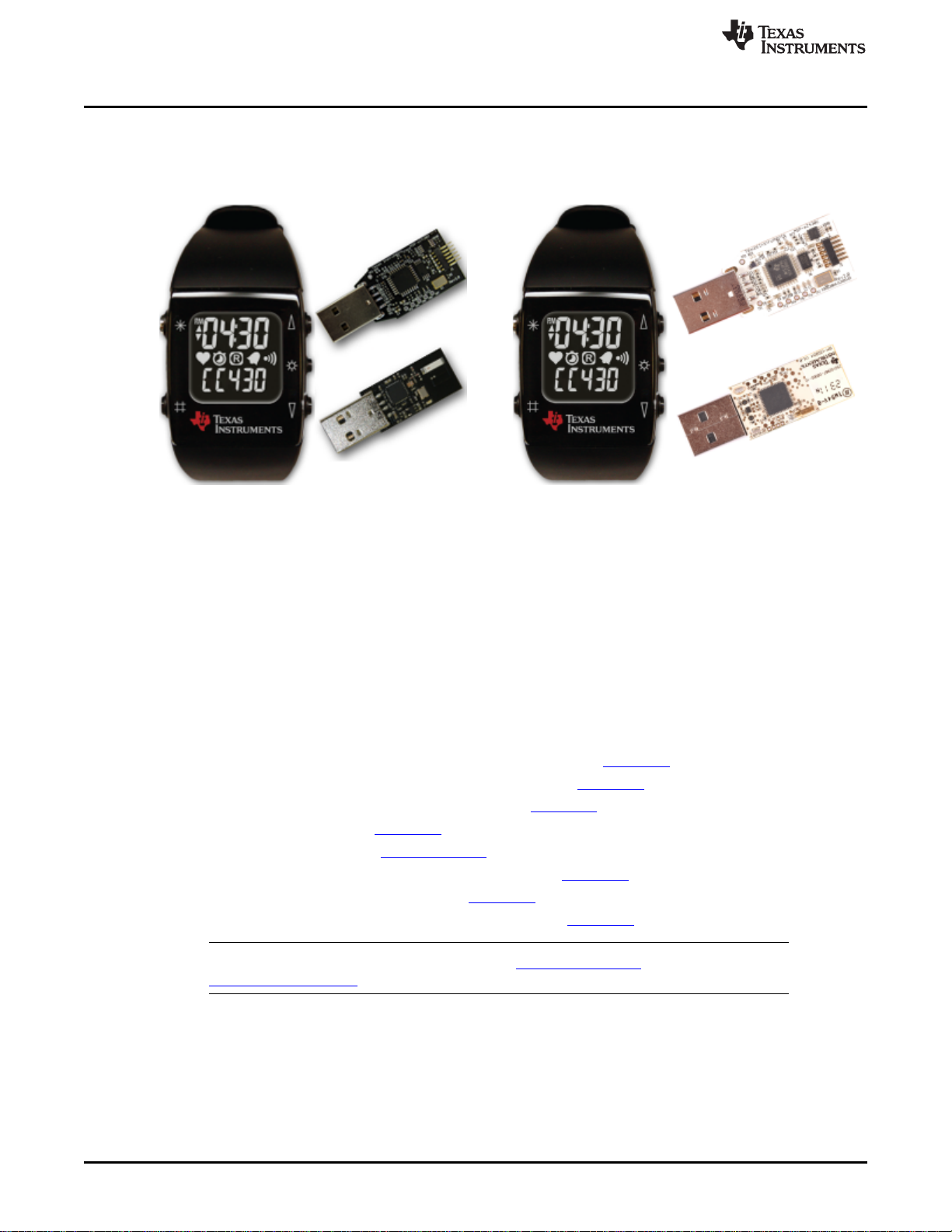
4-27. eZ430-Chronos-868 and -915 Wrist Modules With Black PCBs, Schematics..................................... 81
4-28. eZ430-Chronos-868 and -915 Wrist Modules With Black PCBs, PCB Components on Top Layer............ 82
4-29. eZ430-Chronos-868 and -915 Wrist Modules With Black PCBs, Layout Top Layer (LCD Side) ............... 83
4-30. eZ430-Chronos-868 and -915 Wrist Modules With Black PCBs, Layout Second Layer......................... 84
4-31. eZ430-Chronos-868 and -915 Wrist Modules With Black PCBs, Layout Third Layer............................ 85
4-32. eZ430-Chronos-868 and -915 Wrist Modules With Black PCBs, Layout Bottom Layer (Battery Side)........ 86
4-33. eZ430-Chronos-868 Wrist Modules With White PCBs, Schematics................................................ 89
4-34. eZ430-Chronos-915 Wrist Modules With White PCBs, Schematics................................................ 90
4-35. LCD Segment Map........................................................................................................ 93
4-36. LCD Pinout ................................................................................................................. 94
4-37. eZ430-Chronos-433 RF Access Point With Black PCB, Schematics .............................................. 95
4-38. eZ430-Chronos-433 RF Access Point With Black PCB, PCB Components on Top Layer...................... 96
4-39. eZ430-Chronos-433 RF Access Point With Black PCB, Layout Top Layer ....................................... 97
4-40. eZ430-Chronos-433 RF Access Point With Black PCB, Layout Bottom Layer ................................... 98
4-41. eZ430-Chronos-433 RF Access Point With White PCB, Schematics............................................. 100
4-42. eZ430-Chronos-433 RF Access Point With White PCB, PCB Components on Top Layer .................... 101
4-43. eZ430-Chronos-433 RF Access Point With White PCB, Layout Top Layer...................................... 102
4-44. eZ430-Chronos-433 RF Access Point With White PCB, Layout Bottom Layer.................................. 103
4-45. eZ430-Chronos-868 and -915 RF Access Point With Black PCB, Schematics ................................. 105
4-46. eZ430-Chronos-868 and -915 RF Access Point With Black PCB, PCB Components on Top Layer......... 106
4-47. eZ430-Chronos-868 and -915 RF Access Point With Black PCB, Layout Top Layer .......................... 107
4-48. eZ430-Chronos-868 and -915 RF Access Point With Black PCB, Layout Bottom Layer ...................... 108
4-49. eZ430-Chronos-868 RF Access Point With White PCB, Schematics............................................. 111
4-50. eZ430-Chronos-915 RF Access Point With White PCB, Schematics............................................. 112
4-51. eZ430-Chronos-868 and -915 RF Access Point With White PCB, PCB Components on Top Layer......... 113
4-52. eZ430-Chronos-868 RF Access Point With White PCB, Layout Top Layer...................................... 114
4-53. eZ430-Chronos-915 RF Access Point With White PCB, Layout Top Layer...................................... 115
4-54. eZ430-Chronos-868 RF Access Point With White PCB, Layout Bottom Layer.................................. 116
4-55. eZ430-Chronos-915 RF Access Point With White PCB, Layout Bottom Layer.................................. 117
4-56. USB Debug Interface, Schematic...................................................................................... 120
4-57. USB Debug Interface, Schematic...................................................................................... 121
4-58. USB Debug Interface, PCB Components on Top Layer............................................................ 122
4-59. USB Debug Interface, PCB Components on Bottom Layer........................................................ 122
4-60. USB Debug Interface, Layout Top Layer ............................................................................. 122
4-61. USB Debug Interface, Layout Bottom Layer ......................................................................... 122
B-1. Device Driver installation Wizard for the Access Point ............................................................. 126
B-2. Successful Driver Installation for Access Point ...................................................................... 127
B-3. Access Point Detection for eZ430-Chronos With Black PCB ...................................................... 127
B-4. Access Point Detection for eZ430-Chronos With White PCB...................................................... 127
B-5. Windows Found New Hardware Wizard .............................................................................. 128
B-6. Automatic Driver installation............................................................................................ 128
B-7. Windows Uncertified Driver Installation Warning .................................................................... 129
B-8. Access Point in Windows Device Manager for eZ430-Chronos With Black PCB .............................. 129
B-9. Access Point in Windows Device Manager for eZ430-Chronos With White PCB .............................. 129
B-10. Port Settings for eZ430-Chronos With Black PCB .................................................................. 129
B-11. Port Settings for eZ430-Chronos With White PCB .................................................................. 129
5
SLAU292F–November 2009–Revised October 2013 List of Figures
Submit Documentation Feedback Copyright © 2009–2013, Texas Instruments Incorporated