TEXAS RANGER TR-296GK User manual

- 1 -
TR-296GK/DX
TABLE OF
CONTENTS
PAGE
CHAPTER 1
SPECIFICATIONS
1.0 General . . . . . . . . . . . . . . . . . . . . . . . . . . . . . . . . . . . . . . . . . . . . . . . . . 2
1.1 Transmitter . . . . . . . . . . . . . . . . . . . . . . . . . . . . . . . . . . . . . . . . . . . . . . 2
1.2 Receiver . . . . . . . . . . . . . . . . . . . . . . . . . . . . . . . . . . . . . . . . . . . . . . . . 2
CHAPTER 2
OPERATION
2.0 Introduction . . . . . . . . . . . . . . . . . . . . . . . . . . . . . . . . . . . . . . . . . . . . . . 3
2.1 Control & Connections . . . . . . . . . . . . . . . . . . . . . . . . . . . . . . . . . . . . . 3
2.1.1 Front Panel . . . . . . . . . . . . . . . . . . . . . . . . . . . . . . . . . . . . . . . . . . . . . . 3
2.1.2 Rear Panel . . . . . . . . . . . . . . . . . . . . . . . . . . . . . . . . . . . . . . . . . . . . . . . 5
2.1.3 Frequency Chart . . . . . . . . . . . . . . . . . . . . . . . . . . . . . . . . . . . . . . . . . . 6
2.2 Microphone . . . . . . . . . . . . . . . . . . . . . . . . . . . . . . . . . . . . . . . . . . . . . . 7
2.3.1 Procedure To Receive . . . . . . . . . . . . . . . . . . . . . . . . . . . . . . . . . . . . . . 7
2.3.2 Procedure To Transmit . . . . . . . . . . . . . . . . . . . . . . . . . . . . . . . . . . . . . 7
2.4 Alternate Microphones And Installation . . . . . . . . . . . . . . . . . . . . . . . . 7
CHAPTER 3
CIRCUIT DESCRIPTION
3.0 Introduction . . . . . . . . . . . . . . . . . . . . . . . . . . . . . . . . . . . . . . . . . . . . . . 9
3.1 PLL Circuit . . . . . . . . . . . . . . . . . . . . . . . . . . . . . . . . . . . . . . . . . . . . . . 9
3.2 Receiver Circuit . . . . . . . . . . . . . . . . . . . . . . . . . . . . . . . . . . . . . . . . . . .
9
3.3 Transmitter Modulation Circuit . . . . . . . . . . . . . . . . . . . . . . . . . . . . . . .
9
3.4 Transmitter Amplifier Circuit . . . . . . . . . . . . . . . . . . . . . . . . . . . . . . . . 9
CHAPTER 4
ALIGNMENT
4.0 Required Test Equipment . . . . . . . . . . . . . . . . . . . . . . . . . . . . . . . . . . . 11
4.1 Alignment Procedures . . . . . . . . . . . . . . . . . . . . . . . . . . . . . . . . . . . . . . 11
4.1.1 PLL Alignment . . . . . . . . . . . . . . . . . . . . . . . . . . . . . . . . . . . . . . . . . . . 11
4.1.2 Transmitter Alignment . . . . . . . . . . . . . . . . . . . . . . . . . . . . . . . . . . . . . .
12
4.1.3 Receiver Alignment . . . . . . . . . . . . . . . . . . . . . . . . . . . . . . . . . . . . . . . .
13
CHAPTER 5
MAINTENANCE
5.0 Precautions . . . . . . . . . . . . . . . . . . . . . . . . . . . . . . . . . . . . . . . . . . . . . . 16
5.1 Periodic Inspection . . . . . . . . . . . . . . . . . . . . . . . . . . . . . . . . . . . . . . . . 16
5.2 Fuse Replacement . . . . . . . . . . . . . . . . . . . . . . . . . . . . . . . . . . . . . . . . . 16
CHAPTER 6
DIAGRAMS AND PART LIST
6.0 PCB Layout & Part List . . . . . . . . . . . . . . . . . . . . . . . . . . . . . . . . . . . . 17

- 2 -
TR-296GK/DX
CHAPTER 1
SPECIFICATIONS
1.0 GENERAL
Model TR-296GK / TR-296DX (B),(C)
Frequency Range 26.965 - 27.405MHz.
Emission Modes AM/USB/LSB
Frequency Control Phase Lock Loop (PLL) synthesizer.
Frequency Tolerance ±0.005 %.
Frequency Stability ±0.001 %.
Operating Temperature Range -30°C to +50°C.
Microphone Plug-in dynamic; with push-to-talk switch and coiled
cord.
Input Voltage 13.8V DC nominal ±15%.
Current Drain: Transmit (AM full mod.) <3.5A.
Current Drain: Receiver (Squelched) <0.5A.
(Max. audio output) <1.0A.
Antenna Connector UHF, SO239.
Dimensions 2-3/8”(H) x 7-7/8”(W) x 9-1/4”(D).
Weight 5 lb.
1.1 TRANSMITTER
RF Power Output AM : 4W ; USB/LSB : 12W PEP
RF Transmit Modes AM/USB/LSB
Modulation High and low level Class B, Amplitude Modulation:
AM and SSB.
Spurious Emissions -55 dB.
Carrier Suppression -55 dB.
Audio Frequency Response 300 to 2500 Hz
Antenna Impedance 50 Ohms.
Output Indicators Meter shows relative RF output power, signal strength
and SWR. Transmit LED glows red when transmitter
is in operation.
1.2 RECEIVER
Sensitivity For 10dB S/N (AM) <0.5 µV.
Sensitivity For 10dB S/N (SSB) <0.25 µV.
IF Frequency AM: 10.695 MHz 1st IF, 455 KHz 2nd IF.
Image Rejection -65 dB.
Adjacent Channel Selectivity -60 dB.
RF Gain Control 45 dB adjustable for optimum signal reception.
Automatic Gain Control (AGC) Figure Of Merit 100 mV for 10 dB Change in Audio Output.
Squelch Adjustable; threshold less than 0.5 µV.
Noise Blanker RF type.
Audio Output Power 4 watts into 8 Ohms.
Audio Frequency Response AM and SSB: 300 to 2500 Hz.
Built-in Speaker 8 Ohms, 5 Watts.
External Speaker (Not Supplied) 8 Ohms; disables internal speaker when connected.
(SPECIFICATIONS SUBJECT TO CHANGE WITHOUT NOTICE)
CHAPTER 2

- 3 -
TR-296GK/DX OPERATION
Figure 2-1 Front Panel
2.0 INTRODUCTION
This section explains the basic operating procedures for the TEXAS RANGER TR-296GK / TR-
296DX mobile transceiver.
2.1 CONTROLS AND CONNECTIONS
2.1.1 FRONT PANEL
Refer to the above Figure 2-1 for the location of the following controls.
1. ON/OFF VOLUME CONTROL
Turn clockwise to apply power to the radio and to set the desired listening level.
2. SQUELCH CONTROL
This control is used to control or eliminate receiver background noise in the absence of an incoming
signal. For maximum receiver sensitivity, it is desired that the control be adjusted only to the point
where the receiver background noise is eliminated. Turn fully counter-clockwise, then slowly
clockwise until the receiver noise disappears. Any signal to be received must now be slightly
stronger than the average received noise. Further clockwise rotation will increase the threshold level
which a signal must overcome in order to be heard. Only strong signals will be heard at a maximum
clockwise setting.
3. RF GAIN CONTROL
This control is used to reduce the gain of the receive amplifier under strong signal conditions.

- 4 -
4. SWR CAL CONTROL
This SWR CAL control allows the user to calibrate the SWR meter.
5. MIC GAIN CONTROL
Adjusts the microphone gain in the transmit and PA modes. This controls the gain to the extent that
full talk power is available several inches away from the microphone. In the Public Address (PA)
mode, the control functions as the volume control.
6. S-RF/CAL/SWR SWITCH
In the S-RF position, the meter swings proportionally to the strength of the received signal. When
transmitting, the meter indicates relative RF output power. When in the CAL position, the SWR
meter can be calibrated by adjusting the SWR CAL control. When in the SWR position, the
Standing Wave Ratio is measured.
7. MODE CONTROL
This control allows you to select one of the following operating modes: LSB/AM/USB.
8. CLARIFY CONTROL
Allows tuning of the receive frequency above or below the channel frequency by up to 1.5 KHz.
Although this control is intended primarily to tune in SSB signals, it may be used to optimize AM
signals.
9. CHANNEL SELECTOR
This control is used to select a desired transmit and receive channel.
10. FRONT PANEL METER
The Front Panel Meter allows the user to monitor signal strength, RF output power and SWR level.
11. NB/ANL/OFF SWITCH
In the ANL position, the automatic noise limiter in the audio circuits is activated. When the switch
is placed in the NB/ANL position, the RF noise blanker is also activated. The noise blanker is very
effective in eliminating repetitive impulse noise such as ignition interference.
12. CB/PA SWITCH
The CB is a normal operation of the radio. In the CB position, the PA function is disabled and the
unit will transmit and receive on the speaker that is connected. In the PA position, the radio acts as a
public address amplifier. Your voice will come out of the speaker that have plugged in to the PA.
SP. jack on the rear panel. The radio does not operate when you are in the PA mode.
13. TONE HI/LO SWITCH
This switch is used to shape the tone of the received signal. In LO position, bass is increased and in
HI position, treble is increased.
14. BRIGHT/DIM SWITCH
This switch controls the level of brightness for the meter lamp and channel display LED.
15. TX/RX LED
The red LED indicates the unit is in the transmit mode. The green LED indicates the unit is in the
receive mode.
- 5 -
16. CHANNEL DISPLAY
The channel display indicates the current selected channel.
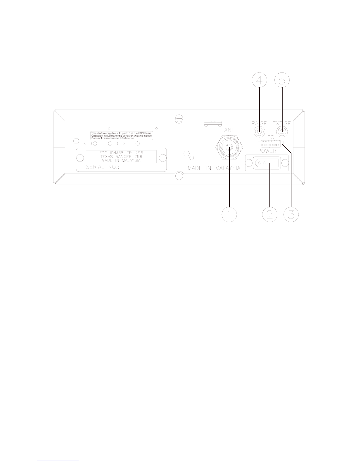
2.1.2 REAR PANEL
Figure 2-2 represent the location of the following connections:
Figure 2-2 Rear Panel
1. ANTENNA
This jack accepts 50 ohms coaxial cable with a PL-259 type connector.
2. POWER
This connector accepts 13.8V DC power cable with built-in fuse. The power cord provided with the
radio has a black and red wire. The black goes to negative and the red goes to positive.
3. FREQUENCY COUNTER CONNECTOR
This F. C. connector is used for an external frequency counter which indicates the frequency of the
selected channel.
4. PA. SP.
This jack is for PA operation. Before operating, you must first connect a PA speaker (8 ohms, 4W)
to this jack.
5. EXT. SP.
This jack accepts 4 to 8 ohms, 5 watts external speaker. When the external speaker is connected to
this jack, the built-in speaker will be disabled.
2.1.3 FREQUENCY CHART
CHANNEL CHANNEL FREQUENCY CHANNEL CHANNEL FREQUENCY

- 6 -
1 26.965 MHz 21 27.215 MHz
2 26.975 MHz 22 27.225 MHz
3 26.985 MHz 23 27.255 MHz
4 27.005 MHz 24 27.235 MHz
5 27.015 MHz 25 27.245 MHz
6 27.025 MHz 26 27.265 MHz
7 27.035 MHz 27 27.275 MHz
8 27.055 MHz 28 27.285 MHz
9 27.065 MHz 29 27.295 MHz
10 27.075 MHz 30 27.305 MHz
11 27.085 MHz 31 27.315 MHz
12 27.105 MHz 32 27.325 MHz
13 27.115 MHz 33 27.335 MHz
14 27.125 MHz 34 27.345 MHz
15 27.135 MHz 35 27.355 MHz
16 27.155 MHz 36 27.365 MHz
17 27.165 MHz 37 27.375 MHz
18 27.175 MHz 38 27.385 MHz
19 27.185 MHz 39 27.395 MHz
20 27.205 MHz 40 27.405 MHz
2.2 MICROPHONE
The receiver and transmitter are controlled by the push-to-talk switch on the microphone. Press the
switch and the transmitter is activated, release switch to receive. When transmitting, hold the

- 7 -
microphone two inches from the mouth and speak clearly in a normal voice. The radio comes
complete with a low impedance (500 ohm) dynamic microphone. For installation instructions of the
microphone, see section 2.4 “ALTERNATE MICROPHONES AND INSTALLATION”.
2.3 OPERATION
2.3.1 PROCEDURE TO RECEIVE
1. Be sure that power source, microphone and antenna are connected to the proper connectors
before going to the next step.
2. Turn unit on by turning VOL knob clockwise on transceiver.
3. Set the VOL to a comfortable listening level.
4. Set the MODE switch to the desired mode.
5. Listen to the background noise from the speaker. Turn the SQ knob slowly clockwise until the
noise just disappears. The SQ is now properly adjusted. The receiver will remain quiet until a
signal is actually received. Do not advance the control too far or some of weaker signals will not
be heard.
6. Set the CHANNEL selector switch to the desired channel.
7. Set the RF GAIN control fully clockwise for maximum receive gain.
8. Adjust the CLARIFY control to clarify the SSB signals or to optimize AM signals.
2.3.2 PROCEDURE TO TRANSMIT
1. Select the desired channel of transmission.
2. Set the MIC GAIN control fully clockwise.
3. If the channel is clear, depress the push-to-talk switch on the microphone and speak in a normal
voice.
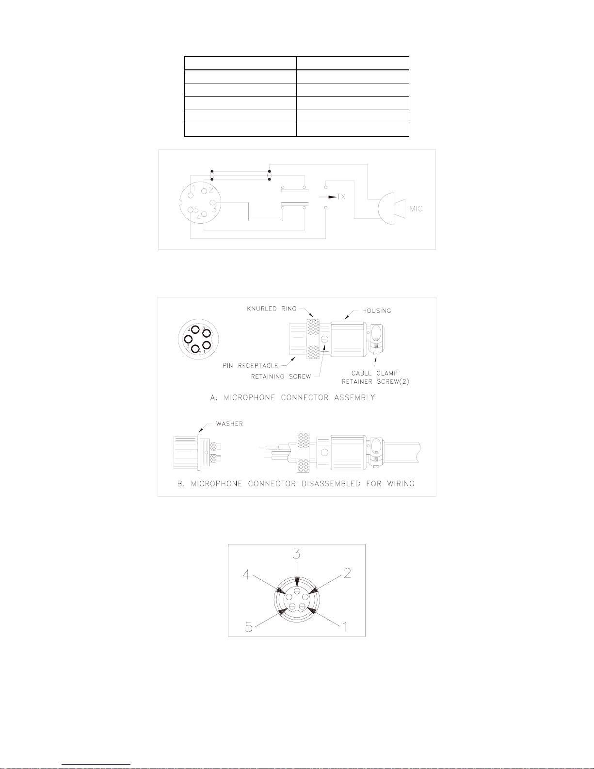
2.4 ALTERNATE MICROPHONES AND INSTALLATION
For best results, the user should select a low impedance dynamic type microphone or a
transistorized microphone. Transistorized type microphones have a low output impedance
characteristic. The microphones must be provided with a five-lead cable. The audio conductor and
its shielded lead comprise two of the leads. The third lead is for receive control, the fourth is for
grounding and fifth is for transmit control. The microphone should provide the functions shown in
schematic below (Figure 2-3).
- 8 -
5 WIRE MIC CABLE
Pin Number Mic Cable Lead
1 Audio Shield
2 Audio Lead
3 Receive Control
4 Grounding
5 Transmit Control
Figure 2-3 Transceiver Microphone Schematic
Figure 2-4 Microphone Plug Wiring
Figure 2-5 Microphone plug pin numbers viewed from rear of pin receptacle.

- 9 -
TR-296GK/DX
CHAPTER 3
CIRCUIT
DESCRIPTION
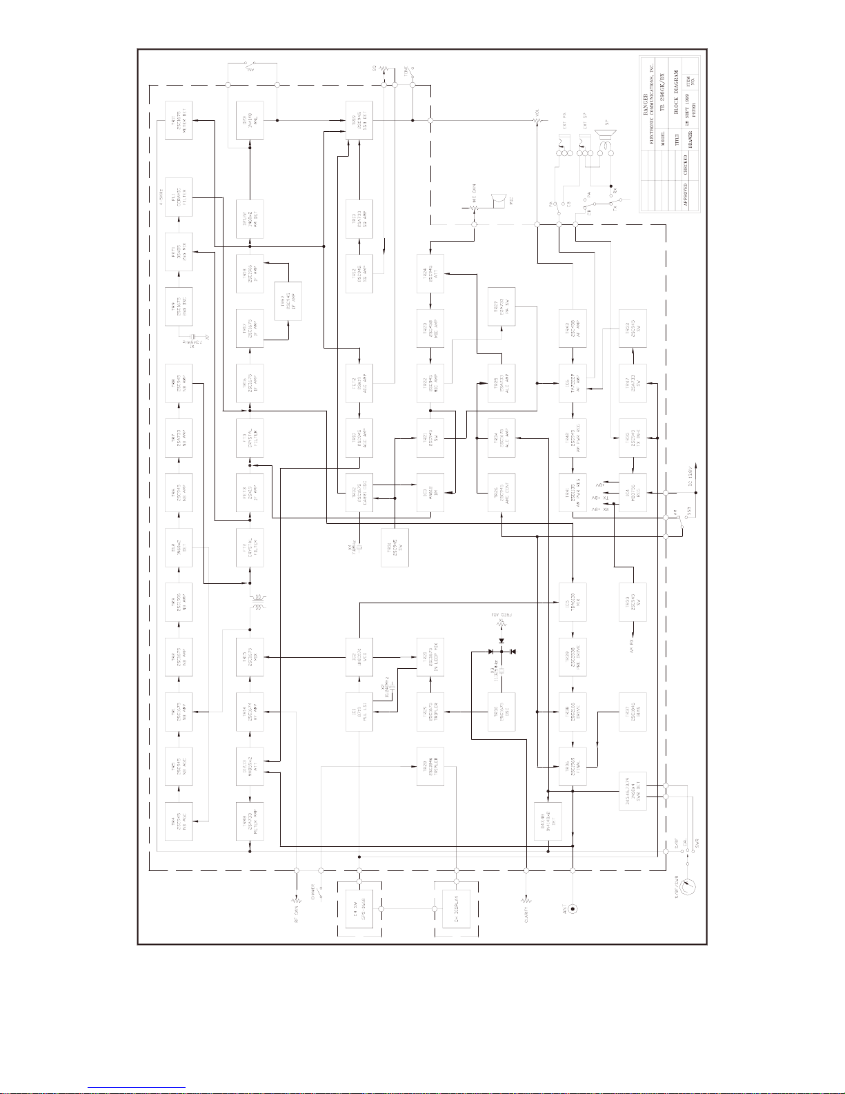
3.0 INTRODUCTION
This section explains the technical theory of operation for the TR-296GK / TR-296DX mobile
transceiver.
3.1 PLL CIRCUIT
The Phase Lock Loop (PLL) circuit is responsible for developing the receiver’s first local oscillator
signal and the transmitter’s exciter signal. The PLL circuit consists primarily of IC1, IC2, TR20,
TR29 and TR30. The PLL circuit is programmed by the rotary channel switch GPS-0668. The GPS-
0668 communicates the correct binary data information to the programmable divider inside of IC1.
IC1 then controls the VCO (Voltage Controlled Oscillator) to oscillate on the correct frequency.
This signal is fed either into the receiver’s first mixer (for receive operation) or the transmitter’s
mixer (for transmit operation).
3.2 RECEIVER CIRCUIT
The incoming receive signal comes into the radio via the antenna and into the first RF amplifier,
TR14. The RF signal is fed into the mixer, TR15 and then into the AM IF section of the receiver
(depending on the mode of operation). The signal is then detected by either the AM detector or
product detector and then fed to the audio amplifier section of the receiver and finally out to the
speaker.
3.3 TRANSMITTER MODULATION CIRCUIT
(i) The transmitter modulation circuit modulates the low level RF signal from the PLL exciter
circuit with the user’s audio voice signal from the microphone. The audio from the microphone
is then amplified and fed into the balanced modulator circuit.
(ii) If the transceiver is in the AM mode, the AF amplifier controls the gain of the last RF amplifier
which produces a true AM signal.
(iii) If the transceiver is in the SSB mode, the audio signal is mixed with 7.800MHz oscillator in
IC3.
3.4 TRANSMITTER AMPLIFIER CIRCUIT
The transmitter takes the basic exciter signal from the TX mixer and amplifies it through a series of
amplifiers consisting of TR39, TR38 and TR36 where it is sent out to the antenna connector.
TR-296GK/DX BLOCK DIAGRAM
- 10 -

- 11 -
TR-296GK/DX
CHAPTER 4
ALIGNMENT
4.0 REQUIRED TEST EQUIPMENT
!DC Power Supply (13.8VDC, 10A)
"RF Wattmeter (25~60 MHz, 25W)
#Multimeter
$Automatic Modulation Meter
%Audio Signal Generator
&Frequency Counter (100 MHz)
'RF Signal Generator (100 MHz)
(Automatic Distortion Meter
)Oscilloscope (50 MHz)
*Sinad Meter
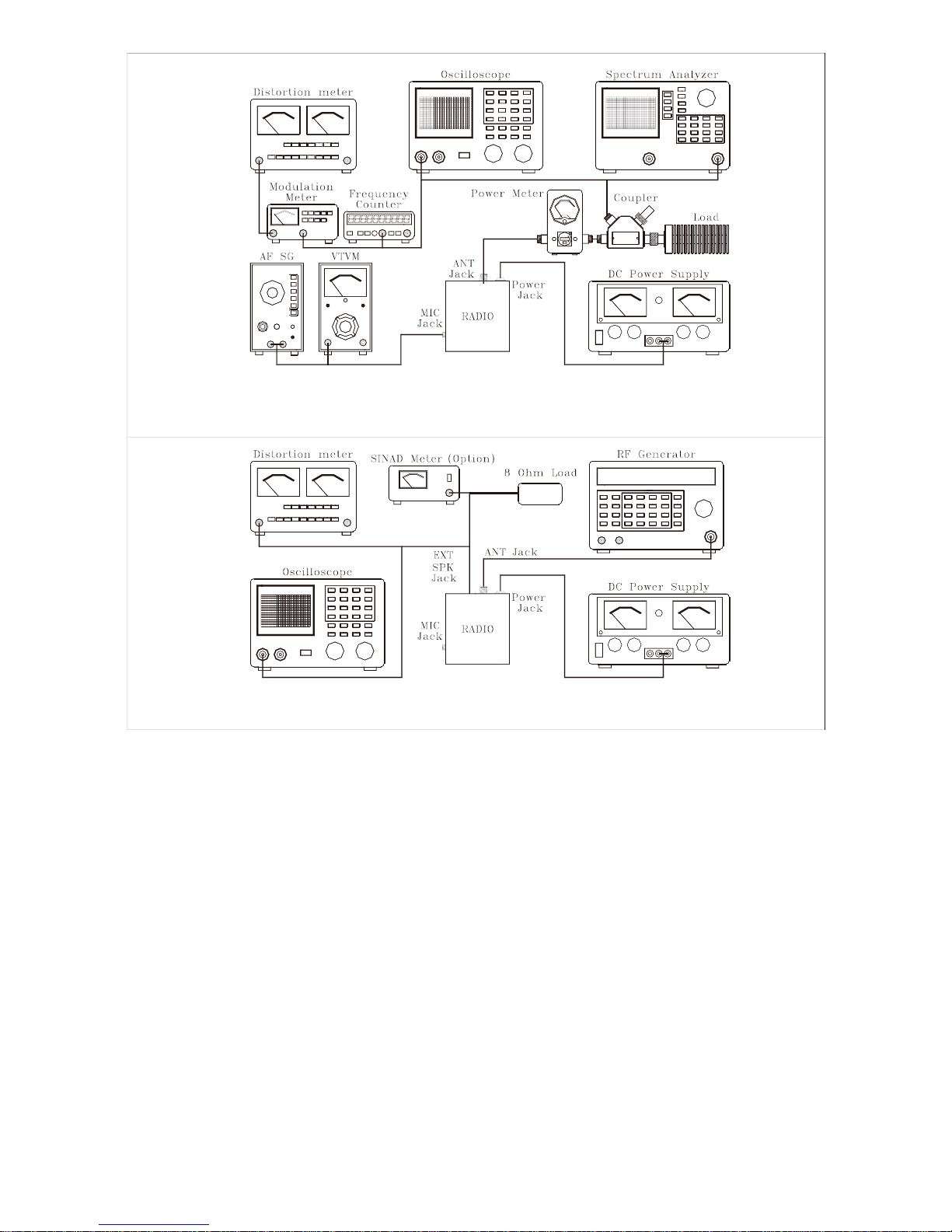
4.1 ALIGNMENT PROCEDURES
This transceiver has been aligned at the factory and does not require any adjustments at installation.
The required test equipment listed are used for the test setup or alignment shown in Figure 4-1
Transmitter Test Setup and Figure 4-2 Receiver Test Setup. These test setup are used in part or total
during the following adjustments and refer to Figure 4-3 for adjustment location.
4.1.1 PLL ALIGNMENT
ITEM U.U.T. SETTING ADJUST
POINT MEASUREMENT
VCO Voltage Set radio to CH 1, AM RX mode.
Clarify setting in 12 o’clock position.
Connect DC Voltmeter to TP9 (R207).
Connect Oscilloscope to TP10 (R101).
Connect Oscilloscope to TP1 (R106).
L19
L21
L20
2.5 VDC ±0.1
CH 1 & CH 40 Max.
Output and Balance.
AM
Frequency Set radio to CH 1, AM RX mode.
Connect frequency counter to TP1 (R106). L23 34.76500 MHz + 20 Hz
LSB Freq. Set radio to CH 1, LSB RX mode.
Connect frequency counter to TP1 (R106). L22 34.76350 MHz + 20 Hz
USB Freq. Set radio to CH 1, USB RX mode.
Connect frequency counter to TP1 (R106). L59 34.76650 MHz + 20 Hz
TX Frequency Set radio to CH 1, AM TX mode.
Connect frequency counter to TP1 (R106). VR5 34.76500 MHz + 20 Hz
AM TX Freq. Set radio to CH 19, AM TX mode.
Set Mic Gain fully counter clockwise. L31 27.18500 MHz + 20 Hz
LSB TX Freq. Set radio to CH19, LSB TX mode.
Set Mic Gain fully clockwise.
AF signal 25 mV, 1 KHz to microphone.
L30 27.18400 MHz + 20 Hz
USB TX Freq. Set radio to CH19, USB TX mode.
Set Mic Gain fully clockwise.
AF signal 25 mV, 1 KHz to microphone.
CT2 27.18600 MHz + 20 Hz
4.1.2 TRANSMITTER ALIGNMENT

- 12 -
ITEM U.U.T. SETTING ADJUST
POINT MEASUREMENT
BIAS Current
Set radio to CH 19, USB TX mode. MOD off.
Connect current meter to TP8 (+) and green
lead wire (-).
Connect current meter to TP7 (+) and violet
lead wire (-).
VR9
VR8
30 mA
50 mA
AM TX Power Set radio to CH 19, AM TX mode.
Connect RF power meter to antenna jack.
MOD off.
L48, L47,
L46, L45,
L38, L36
L38
VR10
RF Power Output
MAX
Balance Power
between CH 1 and
CH 40.
4W.
SSB ALC Set radio to CH 19, USB TX mode.
Set Mic Gain fully clockwise.
AF signal 25 mV, 1 KHz to microphone.
VR11
12 W.
SSB Carrier
Balance Set radio to CH 19, USB TX mode.
Connect Oscilloscope to L44 (TR39C).
Mic Gain off.
VR4 Spurious Emission
to minimum.
AM
Modulation Set radio to CH 19, AM TX mode.
Set Mic Gain fully clockwise.
AF signal 30 mV, 1 KHz to microphone.
VR7 95%
RF Power
Meter Set radio to CH 19, AM TX mode.
MOD off.
VR6 Adjust RF Power
meter needle until it
is in-between the
green and red bar
on PWR scale.
4.1.3 RECEIVER ALIGNMENT
ITEM SETTINGS
ADJUST
MEASUREMENT

- 13 -
POINT
AM Sensitivity Set radio to CH 20, AM RX MODE.
Clarify setting in 12 o’clock.
Set RF gain fully clockwise.
Set SQ fully counter clockwise.
Set VOL control to 2 o’clock.
Set NB/ANL to OFF position.
Connect RF SG to antenna jack.
Frequency 27.205 MHz, Level 1 uV.
MOD 30%, 1KHz.
Set radio to CH 40 AM mode.
RF SG setting 27.405 MHz.
Set radio to CH 1 AM mode.
RF SG setting 26.965 MHz.
L13, L15,
L3, L4, L5,
L6, L7, L8,
L9, L10
Audio output > 2V
S/N > 10 dB
USB Sensitivity
Set radio to CH 20, USB RX mode. MOD off.
Set VOL control fully clockwise.
RF SG setting 27.206 MHz, Level 1 uV.
L12, L14 Audio output > 4.5V
S/N > 20 dB
LSB Sensitivity
Set radio to CH 20, LSB RX mode. MOD off.
VOL control fully clockwise.
RF SG setting 27.204 MHz, Level 1 uV.
L12, L14 Audio output > 4.5V
S/N > 20 dB
NB/ANL Adjust
Set radio to CH 20, AM RX mode.
RF SG setting 27.205 MHz, Level 100 uV.
MOD 30%, 1KHz.
Set NB/ANL/OFF switch to NB/ANL.
Connect Voltmeter to D2 (Cathode).
L1, L2 DC voltage to max.
( >1.5V )
AM Squelch Set radio to CH 20, AM RX mode.
Set SQ control at fully clockwise.
RF SG setting 27.205 MHz, Level 1 mV.
MOD 30%, 1KHz.
VR3
Slowly Adjust very slowly
until quelch just
open
AM S/RF Meter Set radio to CH 20 AM RX mode. MOD off.
Set S-RF/CAL/SWR switch to S/RF position.
RF SG setting 27.205 MHz, Level 100 uV.
VR1 Meter needle to S9
on the S scale
SSB S/RF
Meter Set radio to CH 20, USB RX mode. MOD off.
Set S-RF/CAL/SWR switch to S/RF position.
RF SG setting 27.206 MHz, Level 100 uV
VR2 Meter needle to S9
on the S scale
Figure 4-1 Transmitter test setup
- 14 -
Figure 4-2 Receiver test setup

- 15 -
Figure 4-3 Main PCB Adjustment Location
CHAPTER 5

- 16 -
TR-296GK/DX MAINTENANCE
5.0 PRECAUTIONS
The inherent quality of the solid-state components used in this transceiver will provide many years
of continuous use. Taking the following precautions will prevent damage to the transceiver.
(i) Never key the transmitter unless an antenna or suitable dummy load is connected to the antenna
receptacle.
(ii) Ensure that the input voltage does not exceed 16 VDC or fall below 11 VDC.
(iii) During alignment, do not transmit for more than 10 seconds at a time. Transmitting over long
periods can cause heat built-up and cause transmitter damage.
5.1 PERIODIC INSPECTION
This unit is aligned at the factory to deliver maximum performance. However, continued
performance cannot be expected without periodic inspection and maintenance. Important points to
be checked regularly are as follows;
Check Item Action
Whip antenna
(option) If cracked or broken, replace it.
Coaxial cable If sheath is cracked, seal with
vinyl tape. If immersed with
water, install new coaxial cable.
Coaxial & power
plug connections If loosened, reconnect. If
corroded, clean contacts.
Battery connection If corroded, clean power
terminals.
Ground terminal If corroded, clean terminal.
5.2 FUSE REPLACEMENT
To protect the equipment from serious damage, a fuse is provided on the power supply lines. The
fuse protect against overvoltage / reverse polarity or internal fault of the equipment. If the fuse has
blown, first find out the cause of the trouble before replacing it. A fuse rated for more than 4A
should not be used, since it may permanently damage the equipment. Damage due to overfusing is
not covered by the warranty.
CHAPTER 6
DIAGRAMS &
- 17 -
TR-296GK/DX PARTS LIST
6.0 GENERAL
Information on most electrical and mechanical parts is included in the parts list. The reference
designators are in alphanumeric order.
6.1 ORDERING REPLACEMENT PARTS
Parts orders should be referred to the parts department at:
•Ranger Communications, Inc.
3377 Carmel Mountain Road
San Diego, CA 92121
Tel: 858-259-0287
Fax: 858-259-0437
PART LIST:

- 18 -
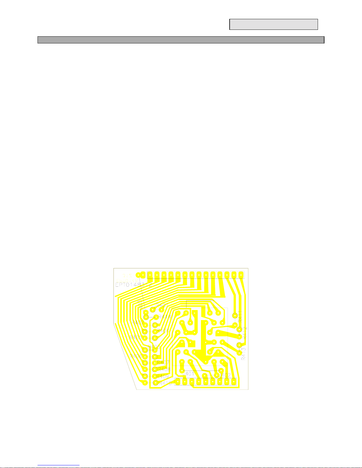
TR-296GK/DX ROTARY SW. P.C.B
ITEM REFERENCE
NUMBER RANGER PART
NUMBER DESCRIPTION
1 EPT014831Z ROTARY SW. P.C.B
2 ROTARY SW PCB EWRT32059S ROTARY SW
3 R401-R414 RCU146814Z 680 ohm 1/4W
4 J402 WX01070705 JUMPER WIRE
5 J401 WX01070715 JUMPER WIRE
6 J403 WX01070712 JUMPER WIRE
REMARK:
SOLDER SIDE (BLUE)
PART LIST:
TR-296GK/DX MIC P.C.B
ITEM REFERENCE
NUMBER RANGER PART
NUMBER DESCRIPTION
1 EPT014840Z MIC P.C.B
2 C404-C407 CC0501027L 0.001µF 50V
3 L404,L405 ECBAD18558 BEAD COIL
- 19 -
REMARK:
LEFT: COMPONENT SIDE
RIGHT: SOLDER SIDE
PART LIST:
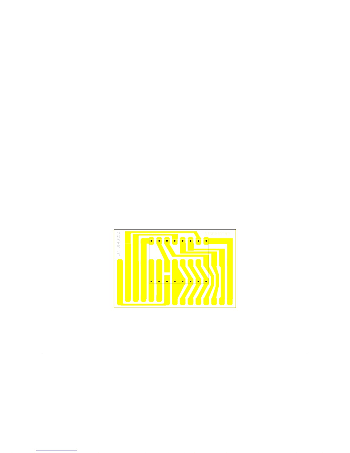
TR-296GK/DX CH DISPLAY P.C.B
ITEM REFERENCE
NUMBER RANGER PART
NUMBER DESCRIPTION
1 EPT014821Z CH DISPLAY P.C.B
2 CH DISPLAY PCB EX03N40003 LED DISPLAY
REMARK:
SOLDER SIDE (BLUE)
This manual suits for next models
1
Table of contents


