Texas T Parts ECHO-F1 User manual
Page 1
Texas Model A Parts
Parts & Accessories for
Model T Fords
1-800-337-6977
Texas T Parts
Texas T Parts
8427 Turkey Creek Road
College Station, Texas 77845
(979) 260-5433
Fax (979) 260-1214
www.TexasTParts.com
DIGITAL SPEEDOMETER KIT INSTALLATION
INSTRUCTIONS
8Function Digital Speedometer
•Speed Functions -- 0-120.0 M/H or K/H
Current Speed
Maximum Speed
Average Speed
•Distance Functions
Odometer (Up to 99,999.9 M or K • Increments of 0.1 M or K)
Trip Odometer (Up to 99,999.99 M or K • Increments of 0.1 M or K)
Day Odometer (Up to 999.99 M or K • Increments of 0.01 M or K)
•Time Function
Current Time
Drive Time
Specifications:
Dimensions: 1.75" X 2" X 0.7"
Weight: 0.5 oz.
Display: Dual liquid crystal, upper numbers 0.3" high; lower numbers 0.2" high
Operational Temperature Range: 0°F to 150°F
Battery: 1.5 volt, approximately 2 year life. Use Maxell LR44 or the equivalent.
Tools Needed for Installation:
Screwdriver Electrical Tape Tap Wrench Floor Jack
Electrical Pliers Small Electric Drill 1/4"-20 Tap 9/64" Drill Bit
Long Nosed Pliers 7/16" Wrench 13/64" Drill Bit
Parts Supplied:
Speedometer Display Head 1-1/4"-20 Hex Head Bolt
Display Head Bracket & Wires with receiver module 1-1/4" Lock Washer
Sender Magnet with Bracket 1 - 1/4" Flat Washer
1-2-3/4" IDEAL hose clamp 8-6" Nylon Tie straps

Speedometer Base Mounting (Fig. 1)
The speedometer base is designed to be mounted on the steering column of
any Model T with the hose clamp provided. To avoid scratching the paint on
the steering column, wrap the column first with 2 or 3 layers of electrical tape
oranother cushioning material. The speedometer may also be mounted
elsewhere if you make another type of bracket. The speedometer head has
been calibrated by Texas T Parts to give accurate MPH reading for Model T
tire sizes. If you need to recalibrate it refer to the directions below.
Wheel Magnet Bracket Mounting (Fig. 2):
It will be necessary to remove your front left wheel in order to install the
wheel magnet. Keep the jack under the front axle near the wheel in order to
adjust the wheel magnet and signal receiver module.
WIRE WHEELS: Drill a 13/64" hole in the hub between two lug bolts and
tap to 1/4"-20. Install the magnet mounting bracket using the 1/4"-20 x 1/2"
bolt, lock washer, & flat washer, and position the magnet as per Figures 2 or 3.
WOOD WHEELS: The bracket may be mounted under one of the hub bolts
and positioned as shown in Figures 2 or 3. Be sure you have enough threads
left to peen the end of the bolt. Do not tighten the nut now. Alternatively, the
magnet may be installed as on wire wheels by drilling and tapping a 1/4"-20
hole and using the bolt provided.
Wiring:
Run the wire down the steering column and along a route that will protect the
wire from being rubbed or cut. Use nylon tie straps or other means to secure
the wire. Run the wires behind the axle, allowing enough slack in the wire
for the spindle to turn from full right to full left freely. Make sure that the
wires will not be rubbed and worn by either the wheel hub or the movement
of the spindle. Note the differences in locating the receiver module for cars
with '26-'27 front hubs.
Slowly rotate the wheel and make adjustments in the location of the wheel
magnet and the receiver module to achieve a maximum of 1/8" clearance
between the two. 1/32” is desirable if your bearings are tight enough to
prevent the wheel from moving enough fot the magnet to hit the pick up unit.
Turn the wheels fully right and left to make sure there is enough slack in the
wires. Make sure the bearings in your wheel are adjusted properly to remove
any play on the axle.
After running the car for a few miles, check all adjustments to be sure that they
remain undisturbed.
Summary of Features
We have pre-set your Speedometer/Computer at Texas T Parts to give the
correct reading for Model T tires. If it has not been changed, you should be
able to install the unit as described above. When you start driving, the
Speedometer will turn on automatically and give you your speed. Instructions
for programming or re-programming the Speedometer are given below.
Auto Start/Stop
To preserve batteries, the speedometer will automatically switch off if the unit
is left unused for 6 minutes. The display will reappear with a press on either button or input from the sensor.
Figure 2 for '09-'25
Figure 3 for '26-'27
Page 2
STEERING
COLUMN
BRACKET
SPEEDOMETER
HEAD
Speedometer Head
Release Clip
Figure 1
1/8”
Maximum
Clearance
1/8”
Maximum
Clearance
Calibration
We at Texas A&T Parts have preset the Digital Speedometer to "Miles" and have set the calibration to the correct setting for Model T
wheels. You may need to reset your computer from time to time. When Daylight Savings Time goes into effect or when you change
your battery for example. W are including the instructions for setting the Speedometer that came with it, but they were written by
Geeks for Geeks, so we have tried to write the following Human for Human instructions.
Getting Started
First, remove the Speedometer Head from it’s bracket by depressing the Speedometer Head Release Clip and
lifting the head upward.
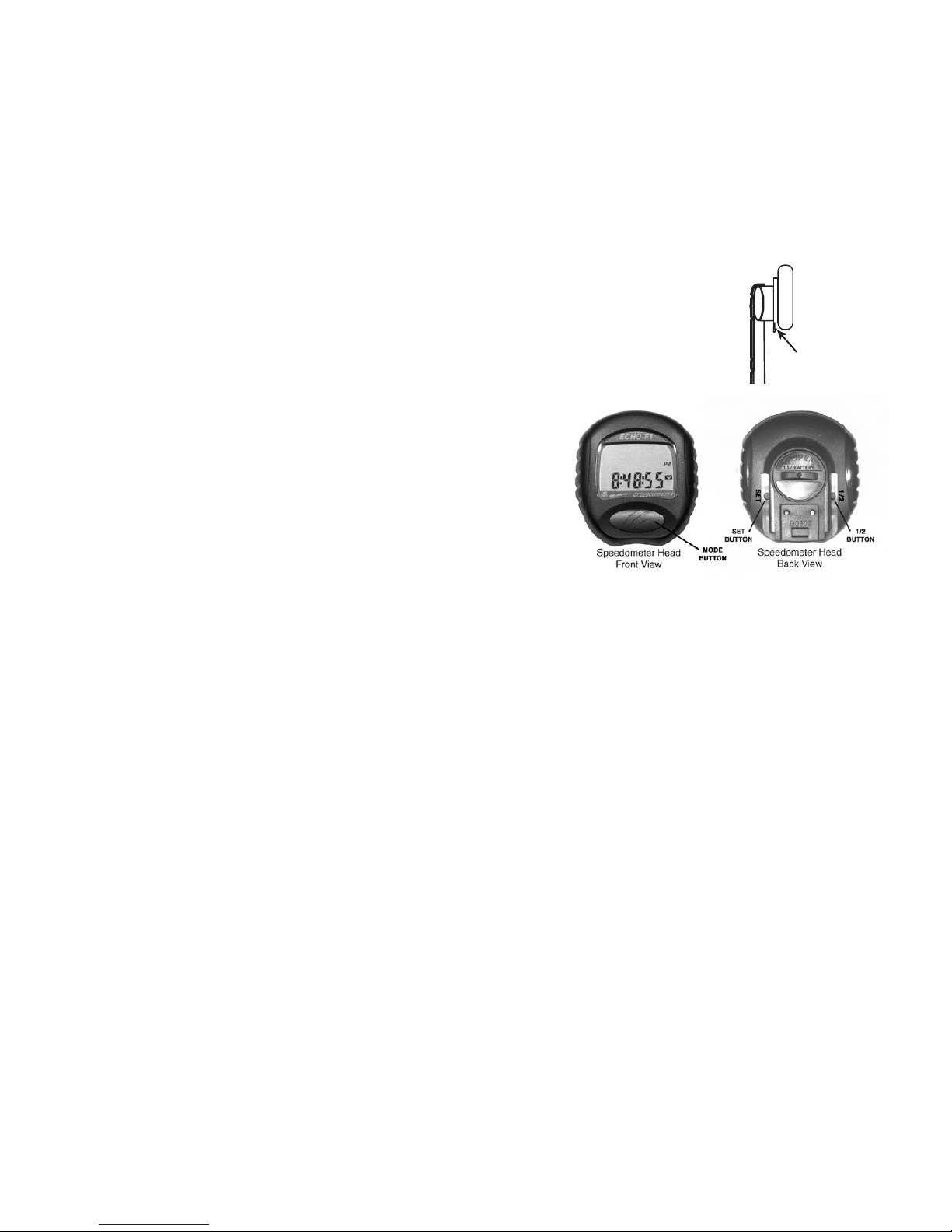
Familiarize yourself with the programming buttons of the Speedometer head.
You will find the MODE button on the front of the display and the SET and 1/2 buttons on the back of the
display. You will need to use a paperclip to depress the SET and 1/2 buttons.
The large digits on the top line always will display your speed in Miles Per
Hour or Kilometers Per Hour.
The MODE button is used to change the second line display between the
various other readouts such as the Odometer, Trip Odometer, Time, Average
Speed, Maximum Speed, Trip Odometer (since reset), and Day Odometer
(miles driven this day). You can reset some of the displays simply by
selecting that display and then pushing the SET button momentairly.
In order to get started you should reset the entire unit by pushing the MODE
button on the front and simultaneously depressing the 1/2 button on the back
and holding both for 4 to 5 seconds. The entire front display will then flash all images. In order to stop the images flashing and beguin
the setup process, momentairly push the MODE button. You will see the Km/h image flashing on the display.
With the Km/h flashing you can momentairly press the MODE button and it will change to Mile/h. You will probably want the
speedometer to measure Mile/h so to select that option, while Mile/h is displayed, momentairly push the SET button on the back with a
paper clip. The display will now show ODO (1) and display
00000.0
with the left zero flashing.
If you want to set the starting odometer at a reading that will reflect mileage already on the car, you can change the digits of the
odometer reading by momentairly pressing the MODE button. When you have set the digit to your desired setting press and hold the
MODE button until the flashing digit changes to the next digit to the right. Continue changing the digits on the odometer until you get
the mileage reading you want to set. Then momentairly press the set button on the back. You will have the opportunity to set an
odometer ODO (2) setting just like the ODO (1) but most Model T owners will not want to use that feature so I will skip it. (If you want
to explor further, we have included the Geek to Geek instructions for your pleasure.)
If you are going to start using your speedometer and start your mileage from zero then press the SET button momentairly three more
times which will bring up the calibration screen displaying
2155c 1
and proceed to the next step.
For a Model T we need to set the calibration to read
2375c 1
.While the
2
is flashing if you hold the MODE button for 4 seconds it will
advance to the second digit (the
1
). Depress the MODE button momentairly 2 times to advance to a
3
digit and then depress and hold
the MODE button for 4 seconds to advance to the first (
5
)digit. Depress the MODE button momentairly 2 times to advance the
5
to a
7
digit. The readout should now read
2375c 1
.When this is achieved, momentairly depress the SET button on the back.
Your digital speedometer is now set to record your speed and distance traveled based on the diameter of your 30 x 3-1/2” or 21” tires.
Install the Speedometer Head back in the bracket on the steering column and enjoy know how fast you go and how far you travel.
STEERING
COLUMN
BRACKET
SPEEDOMETER
HEAD
Speedometer Head
Release Clip
Page 3

Battery & Troubleshooting
Installing a New Battery
Toremove the battery, unscrew the cap on the back of the Speedometer Head with a screwdriver. Install the new battery with its
positive (+) side toward the cap, then screw the cap back into the head with a screwdriver.
When you replace the battery, be
careful not to bend any of the three small battery contacts around the perimeter of the battery. We have found that they are easily bent
and the battery will not fit in properly until the situation is corrected.
Use a Maxell LR44 battery or the equivalent. Removing the
battery erases all stored data and resets the calibration number to 2155 so it will affect the accuracy of the speed readings. Refer
to the section on calibration for resetting the data.
Troubleshooting
Speed and distance seem too high or too low.
1. Check calibration number. It should be 2375 for a standard Model T tire.
2. Check spacing between wheel magnet and receiver module.
No speed or distance.
1. Check spacing between wheel magnet and receiver module.
2. Check the contacts on the back of the speedometer head and the mounting bracket. Clean with an eraser if needed.
3. Check for a broken wire.
No display or display is dim.
1. Replace Battery
Incorrect data or unusual display
1. Remove battery, then reinstall after waiting 15 seconds.
Reset/Power Saver
Automatic Power Saver: After no buttons have been pressed and no wheel movement has been detected for 6 minutes, the display will go blank.
Power consumption is reduced by 50%. The normal display returns when a button is pressed or the car is moved.
If you like our product, tell your friends. If you have a question or a problem, let us know.
Thanks, and Smooth Running,
TEXAS ‘A&T’ PARTS
LIMITED WARRANTY
Texas ‘A&T’ Parts will repair or replace any part that we manufacture, for a period of 90 days from the date of purchase, that wears out or breaks.
Since we don’t install parts, the part must be installed on the type of individually owned and operated passenger vehicle for which it is designed. Of course, we cannot replace a
part whose failure was caused by another faulty part, low fluid, or other abuse.
Return any part directly to us, along with a copy of the sales receipt showing the date of purchase, and $5 to cover shipping & handling. Do not return parts to your dealer.
That’s what our warranty means in plain English, but we regret we must include this legalese, too: THIS LIMITED WARRANTY REPRESENTS THE TOTAL LIABILITY
OF TEXAS ‘A&T’ PARTS FOR ANY WARRANTED PART, AND TEXAS ‘A&T’ PARTS MAKES NO OTHER WARRANTIES, EXPRESS OR IMPLIED,
INCLUDING THE IMPLIED WARRANTIES OF MERCHANTIBILITY OR FITNESS FOR A PARTICULAR PURPOSE. TEXAS ‘A&T’ PARTS SHALL NOT BE
LIABLE FOR ANY INDIRECT, SPECIAL, INCIDENTAL, OR CONSEQUENTIAL DAMAGES. Texas ‘A&T’ Parts reserves the right, at its option, to refund the
customer’s money instead of replacing a part. This warranty does not cover parts that are installed on marine, off-road, commercial, or government vehicles, or stationary
units.
Page 4
Table of contents


