Tekon 960 User manual

Battery Quality Analyzer
User Manual
Ⓒ2020 TEKON, Inc
2020.10 Ver 3

INDEX
General................................................................................................................................................ 1
International Standard Safety Symbol ....................................................................................1
Measurement Range (Over voltage range) definition.............................................................2
Opening Package.............................................................................................................2
1. Description and Specifications ................................................................................................. 3
1.1. Product Description........................................................................................................3
1.1.1. Main features.......................................................................................................3
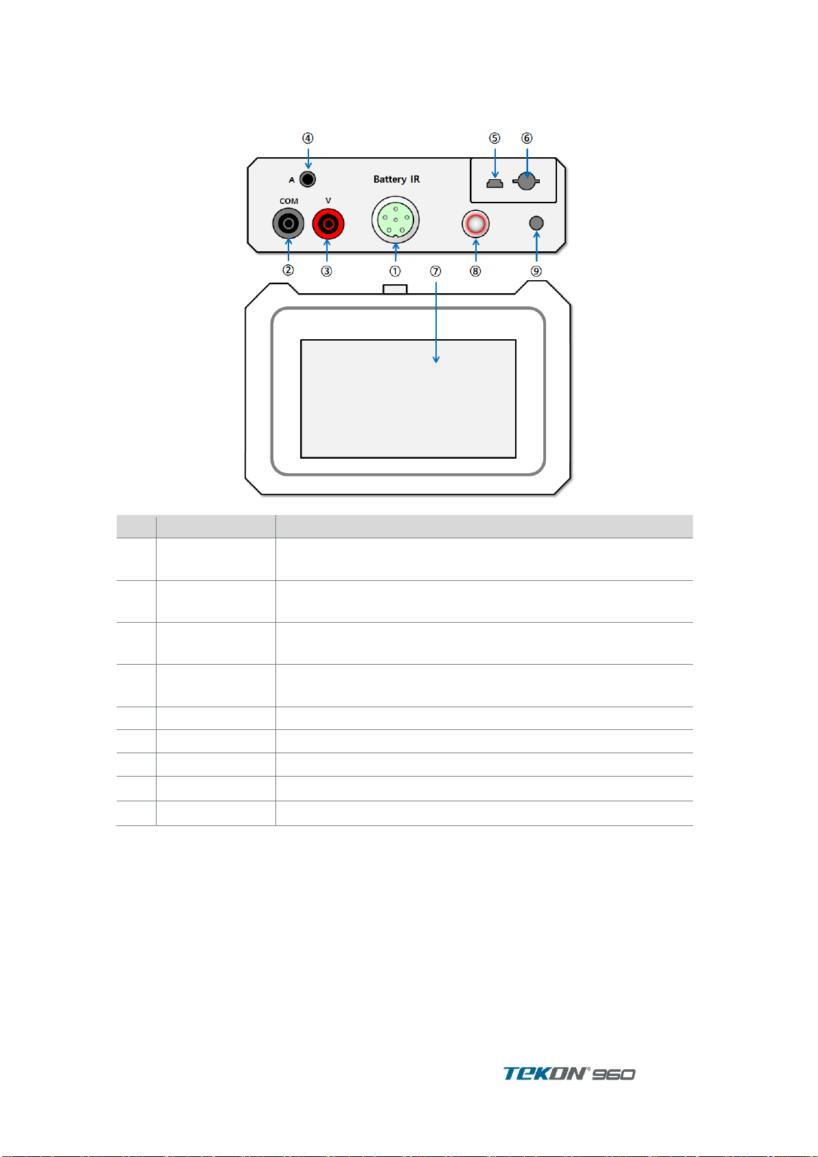
1.2. Description of each part and functions ..........................................................................4
1.2.1. Exterior................................................................................................................. 4
1.2.2. Display.................................................................................................................5
1.3. Ordering information ......................................................................................................7
1.3.1. Accessories and parts ......................................................................................... 7
1.4. Specifications.................................................................................................................9
1.4.1. Power Supply....................................................................................................... 9
1.4.2. Mechanical Specifications ...................................................................................9
1.4.3. Operating Specifications......................................................................................9
1.4.4. Safety Specifications ........................................................................................... 9
1.4.5. Record Capacity.................................................................................................. 9
1.4.6. Electrical Specification.......................................................................................10
1.5. How to hang it around your neck and measure it........................................................11
2. Set Up.......................................................................................................................................... 12
2.1. Power ON/ OFF ...........................................................................................................12
2.2. Keyboard......................................................................................................................12
2.3. User Set Up..................................................................................................................13
2.3.1. User Set Up display...........................................................................................13
3. Impedance Measurement ........................................................................................................ 14
3.1. Insert Test Probe .........................................................................................................14
3.2. “O” adjustment .............................................................................................................14
3.3. Record Mode................................................................................................................15
3.4. Meter Record ...............................................................................................................16
3.4.1. Impedance Measurement (Meter Record).........................................................17
3.4.2. Range Adjustment.............................................................................................17
3.4.3. Hold....................................................................................................................17
3.4.4. AutoHold............................................................................................................17
3.4.5. AutoRec.............................................................................................................17
3.5. Limit..............................................................................................................................18
3.6. String Record...............................................................................................................20
3.6.1. Screen Measurement ........................................................................................20
3.6.2. String record measurement...............................................................................22
3.7. Logger (TEKON960B Only).........................................................................................23
3.8. Noise Avoidance (TEKON960B Only) .........................................................................26
4. V.A measurement ...................................................................................................................... 27
4.1. Test Probe Insert .........................................................................................................27
4.2. Measurement Set Selection.........................................................................................27
4.3. VA Meter......................................................................................................................28
4.3.1. Range Adjustment.............................................................................................29
4.3.2. Hold....................................................................................................................29
4.3.3. AutoHold............................................................................................................29
4.3.4. AutoRec.............................................................................................................29
4.4. VA String......................................................................................................................30

5. Record ......................................................................................................................................... 31
5.1. General ........................................................................................................................31
5.2. Meter Record ...............................................................................................................32
5.2.1. Meter record view..............................................................................................32
5.2.2. Meter Record Delete..........................................................................................33
5.3. String Management......................................................................................................34
5.3.1. String Listing......................................................................................................34
5.3.2. String Edit ..........................................................................................................35
5.3.3. Delete string.......................................................................................................36
5.4. String record management ..........................................................................................37
5.4.1. Impedance record..............................................................................................37
5.5. V.A Record...................................................................................................................39
6. Analysis ....................................................................................................................................... 40
6.1. General ........................................................................................................................40
6.2. Use analysis function...................................................................................................40
6.2.1. Cell analysis.......................................................................................................40
6.2.2. Slot Analyzer......................................................................................................42
7. PC S/W ........................................................................................................................................ 43
7.1. General ........................................................................................................................43
7.2. Requirement.................................................................................................................43
7.3. PC S/W Installation......................................................................................................44
7.4. How to use S/W ...........................................................................................................45
7.4.1. Connection.........................................................................................................45
7.4.2. String list............................................................................................................46
7.4.3. String..................................................................................................................47
7.4.4. Impedance record..............................................................................................48
7.4.5. Cell record .........................................................................................................50
7.4.6. Replay................................................................................................................51
7.4.7. S/W erase..........................................................................................................51
8. Android APP............................................................................................................................... 52
8.1. Install............................................................................................................................52
8.2. Connection...................................................................................................................52
8.3. Using the menu............................................................................................................53
8.3.1. Meter –Impedance record.................................................................................53
8.3.2. Meter –VA record..............................................................................................54
8.3.3. String –Impedance record ................................................................................54
8.3.4. Record ...............................................................................................................55
8.3.5. String –VA record .............................................................................................56
8.4. Share record ................................................................................................................57
8.5. String management......................................................................................................58
8.5.1. Add string...........................................................................................................58
8.5.2. Edit, delete string...............................................................................................58
9. Maintenance............................................................................................................................... 59
9.1. Battery Charging..........................................................................................................59
9.2. Cleaning and Storage ..................................................................................................59
9.2.1. Unit Cleaning .....................................................................................................59
9.2.2. Storage ..............................................................................................................59
9.2.3. Cleaning of Probe..............................................................................................59


User Manual
1
General
Warning
Please use the unit after read Safety Information.
Use only the designated operation method.
Do not use environments in combustible gas, steam or humid.
Do not use damaged unit.
Do not use any unit with abnormal operation.
Do not apply over voltage more than rated voltage between Terminal or between respective
terminal and Ground.
Use appropriate Terminal, range, function or Range when measurement.
Replacement parts should be manufacturer’ designated parts.
Before Battery replacement, be sure to disconnect any Power Code, Test Lead, accessories
from the unit.
International Standard Safety Symbol
Symbol
Description
Double insulated protection
Warning. User should read marking area in the manual and need pay
attention.
If user does not follow the Warning –safety information, user may have physical
injury and the Unit, system may be damaged
Pay attention “Electric Shock”
Voltage in this symbol may be hazard
Disposal information

2
User Manual
Measurement Range (Over voltage range) definition
Higher Category indicates Higher Over Voltage Electric environment. Tester designed for CAT
III environment can withstand higher voltage than the tester designed for CAT II
To avoid any serious accident while measurement, better to use Tester higher category for the
testing environment. For example, do not use Tester with CAT at testing environment CAT II, III,
or IV
Category
Description
CAT I
2nd electric circuit connecting Transformer
example : protected electric circuit
CAT II
Basic circuit of things which electric code is connected to AC consent /Outlet.
example : equipments, portable tool, home apparatus etc.
CAT III
Electric circuit of fixed facilities which directly connected to Consent and
distribution board / Switching board.
example : fixed facility Switch or industrial equipment firmly connected to fixed
facility
CAT IV
Electric circuit from Entrance to Overvoltage protection system (Distribution
board/Switch board ) and Wattage Meter
Example : Electric meter and primary Over- current protector
Opening Package
After delivered, check the package whether the packing materials are correct with Order list. If
any missing or damaged found, please do not use and report it to the supplier. Be sure to keep
the original packing material to support Claim process.
The Battery packed may be drained out during delivery. Please recharge the battery before start
use the unit.

User Manual
3
1.Description and Specifications
1.1. Product Description
TEKON960 measures Internal Resistance, Voltage and Temperature simultaneously which
determine Battery Deterioration status.
Depend on model, can measure Internal Resistance of High Voltage Battery max 200V or 500V.
Using string records designed for battery maintenance, measurement data can be
systematically accumulated and stored to analyze deterioration trends and refer to them in
predicting replacement timing.
Saved data is transmitted and managed to PC S/W via Bluetooth, and export to Excel file, chart
analysis, and report file generation are possible using S/W.
Measurement data can be transmitted remotely using a mobile app.
1.1.1. Main features
Can measure without stopping UPS system.
High precision AC resistance measurement technology enables to measure UPS system
while UPS system in being loaded.
Precise measurement
AC 4–terminal test lead enables precise measurement of internal Resistance of Battery
without affecting Test Probe own resistance and contacting resistance.
Simultaneous measurement of Resistance, Voltage, Temperature, Currents.
Without changing Function, Resistance–Voltage-Temperature or Voltage-Temperature or
Voltage-Currents can be measured simultaneously. Current measurements need to use
external Current Adapter.
LIMIT
LIMIT function can set up Limit of Resistance and Voltage. This enables to determine Battery
Deterioration status when measurement
SD Card
SD card is used to store measurement data. Over 100,000 measurements are stored.
AutoRec (Auto Record)
Use this mode to record measurement data automatically at designated record post. Can
measure many batteries consecutively and conveniently.
PC S/W
Measured data can be downloaded to PC which saved Data enables to String Edit, Record
Erase.
Pin type test probe
End of Pin of Pin Type test probe may insert into 5 mm diameter hole which can measure
battery terminal without Battery Terminal Cover off.
Ripple Voltage measurement
By measuring the DC circuit of the inverter to charge and measuring the voltage ripple (AC
component remaining).
A large ripple voltage is one of the causes for accelerating the battery deterioration

4
User Manual
1.2. Description of each part and functions
1.2.1. Exterior
No
Function
Decription
①
Impedance
Input
This is an impedance measurement input terminal for inserting a
4-terminal probe.
②
VOLTAGE
INPUT
V.A voltage measurement input terminal to insert DMM probe
③
Voltage +
Input Terminal
V.A voltage measurement input terminal to insert DMM probe
④
Current
Input Terminal
This is the current input terminal to connect the current clamp.
⑤
USB Socket
Insert USB cable for communication
⑥
SD Card Slot
Insert the SD card for data storage.
⑦
Display
LCD screen with touch input
⑧
Power S/W
Turns the power on and off.
⑨
Adaptor Socket
Power adapter socket for charging

User Manual
5
1.2.2. Display
The unit shows different display by different measurement functions.
Below explains Display Configuration showing on most function displays.
No
Name
Description
①
Main Function
각아이콘을 터치하여 주기능을 선택합니다.
Lock or unlock screen touch input.
. Switch to impedance measurement function
Switch to voltage and current measurement function.
Switch to record function.
Create strings or check stored records
Delete unnecessary data.
Switch to analysis function.
Use the stored data to analyze the deterioration of the
battery.
Switch to setting function.
Change instrument or measurement settings.
②
Function Tap
The functions under the main function are displayed as tabs.
Touch to select.
③
Softkey
The name of the function performed when F1~F6 is pressed and the
label of the selected item are displayed if selection is possible.
④
Display
The content of the selected function is displayed.
⑤
Display Name
The name of the currently displayed function is displayed.
⑥
Time
The current time of the product is displayed.
Used as time information when saving records.

6
User Manual
⑦
Status icon
SD Card Icon
USB/Bluetooth icon
Volume of the Buzzer
Battery remain
Power adapter is on
SD card slot is empty.
I have an SD card.
SD card is being read or written.
SD card mount failed.
Bluetooth connection is possible.
Connected to PC via Bluetooth
USB cable is connected.
Bluetooth is disabled.

User Manual
7
1.3. Ordering information
1.3.1. Accessories and parts
Impedance Test Lead
Test Lead ( multimeter )
TKP01-500
TP9
AC Adapter
Bluetooth Dongle
T25A (DC12V 2.5A)
T400 (BTU400)

8
User Manual
Carry Bag
Pouch(TEKON960B)
T50A
“0” Adjust Bar
Battery Pack
TP04
TB06A
Current Clamp(TEKON960B)
T130BE

User Manual
9
1.4. Specifications
1.4.1. Power Supply
AC Charging Adapter
Input
: AC 100V ~ 240V @ 50Hz/60Hz
Output
: DC 12V 2.5A
Battery Pack
Type
Li-Ion Rechargeable Battery Pack > 5.4Ah
Voltage Rating
7.4V
Charging Time
4Hr
Battery Life
> 8 Hr, 300 Charging / Discharging cycle
1.4.2. Mechanical Specifications
Dimensions : 240 X 160 X 65 mm
Weight : 0.9㎏
Shock and Vibration : EN 61010-1
Standard : IP 54 EN 60529 (Electic IP2X terminal)
1.4.3. Operating Specifications
Operating Temperature
0 ~ 50°C / 32 ~ 122°F
Storage Temperature
-20 ~ 50°C / -4 ~ 122°F (<30 days )
Charging Temperature
(40 °C ~ 10 °) 104 °F ~ 50 °
Altitude
Operation : 0~2,000m (6,560 ft)
Non-Operation : 0 ~ 10,000 meter (32,800 feet )
Relative Humidity
10~85%
1.4.4. Safety Specifications
Safety
500V CAT III, Pollution Degree 2
IEC 61010-1:2010(3rd Edi.)
EN 61010-1:2010(3rd Edi.)
Testing Equipment Interchangeability
IEN 61326-1:2013
EN 55011/A1:2010 (Class A)
EN 61000-3-2:2014
EN 61000-3-3:2013
1.4.5. Record Capacity
Internal 8MB Flash Storage
Record
Meter mode
String Mode
Impedance Record
<Ω, Volt, Temperature, Time>
Max 1000 record
1 Slot. max 512 cell record.
60 time measurement per string
V.A record
<V DC, V ripple>,<V DC, A
DC>,
<V AC, A VC>
Max 1000 record
512 record per string

10
User Manual
1.4.6. Electrical Specification
Accuracy is specified for a period of one year after calibration, at 18℃to 28 ℃with relative
humidity to 80 %. Accuracy specifications are given as: ±([% of reading] + [number of least
significant digits]). Accuracy specification assumes ambient temperature stable ±1℃.
Warm up time : about 30 minutes
Internal Resistance
Range
Resolution
Accuracy
3mΩ
1uΩ
±1.0%rdg±10dgts
30mΩ
10uΩ
±0.8%rdg±10dgts
300mΩ
100uΩ
3Ω
1mΩ
30Ω
10mΩ
300Ω
100mΩ
3kΩ(model B only)
1Ω
When measuring a high-voltage battery of 100V or more, there is a danger of electric shock.
After discharging the measurement probe after measurement, proceed to the next
measurement.
Voltage (DC/AC)
Range
Resolution
Accuracy
DC 5V
0.001V
±0.5%rdg±5dgts
DC 50V
0.01V
DC 500V
0.1V
DC 1000V
1V
AC 5V
0.001V
±0.75%rdg±5dgts(40㎐~100㎐)
AC 50V
0.01V
AC 500V
0.1V
AC 600V
1V
Currents (DC/AC)
Range
Resolution
Accuracy
DC 4A
0.001A
±0.5%rdg±5dgts + CT tolerance
DC 40A
0.01A
DC 400A
0.1A
DC 1000A
1A
Range
Resolution
Accuracy
AC 4A
0.001A
±0.75%rdg±10dgts + CT Tolerance
AC 40A
0.01A
AC 400A
0.1A
AC 1000A
1A
CT’ own tolerance affects to testing accuracy of measurement. Need to check CT’ own
tolerance before measurement.
Current Adaptor : 1A to 1㎷

User Manual
11
Temperature
Range
Resolution
Accuracy
-10℃~100℃
0.1℃
±1℃+2dgts
Ripple Voltage
Range
Resolution
Accuracy
0~5V
0.001V
±5%rdg±10dgts(40㎐~10㎑)
Current Probe Accuracy
TEKON130BE
Ratio
0-40A
10mv/A
AC Amps
0-40A
±(1.5%+6digits)
DC Amps
0-40A
±(1.5%+5digits)
1.5. How to hang it around your neck and measure it
[Preparation for measurement]
Connect 4 connecting strings to the hooks at the corners of the product.①
Combine the bag straps marked on the bag with 2 hooks each.②
Adjust the length of the bag strap to suit the user and hang it on the neck.③

12
User Manual
2.Set Up
2.1. Power ON/ OFF
Press longer “POWER” key longer than 2 seconds to activate power ON/OFF
2.2. Keyboard
Use when input Name or Number etc
While keyboard is displaying, can input letters with buttons on the unit (except Power button).
English only. If prefer Korean, use PC S/W.
[문자열입력]
Press and hold to enter numbers and special characters.
Shift and transfer to Caps lock and un-lock.
, and move the cursor push or touch the outside of keyboard and
finishe the Input mode.
[Numeric key input]
Touch each number to enter it.
, Press to move the cursor.
Touch outside the keyboard area to finish typing.
→
←
✔
→
←
↑

User Manual
13
2.3. User Set Up
2.3.1. User Set Up display
No
Item
Setting scale
Description
①
Language
Korean, English
Set the display language.
②
Brightness
1~10
Adjust the screen backlight brightness.
③
Screen turns
off
OFF, 3, 5, 10, 15, 30,
60(minutes)
The screen turns off automatically if there
is no operation for the set time. After it
turns off, you can turn it on again by
touching the screen or by shortly pressing
the power button.
④
Time
-
Set the time.
⑤
Volume
Mute, 1 ~ 3
Mute or adjust the volume of the device's
buzzer sound.
⑥
Auto power off
Off, 5, 10, 30, 60(minutes)
If there is no button operation for the set
time, the power is automatically turned
off.
It does not operate when AC power is
connected or during recording function.
⑦
SD format
-
LCD contrast
⑧
Initialization
-
Initialize the device settings.

14
User Manual
3.Impedance Measurement
3.1. Insert Test Probe
For safe and accurate measurement, insert precisely the probe provided with unit.
4 Terminal Pin type probe provided to measure Impedance
Insert Probe to Ω-H, Ω-L terminal.
Be careful any physical injury from the sharp end –Pin type probe
When measuring a high-voltage battery of 100V or more, there is a danger of electric shock.
After discharging the measurement probe after measurement, proceed to the next
measurement.
3.2. “O” adjustment
For accurate Ohm measurement, proceed “O” Ohm adjustment when change Probe.
[Parallel Pin Type]
[Coaxial Pin Type]
Parallel Tip Type : The protruding side is the source and the other side is the sensor.
Coaxial Pin Type : The outside is the source and the inside is the sensor.
Source Pin is connected to the upper side and Sensor Pin is connected to the metal part
below.

User Manual
15
[“0” adjustment]
Press to display the impedance meter screen①
Press and press .②
Wait up to 10 seconds until the probe is touched on the zero adjustment bar.③
Insert the pin end of the measuring probe into the hole of the zero point adjustment plate,④and press the probe perpendicular to the adjustment plate so that the SOURCE and SENSE
terminals of the probe tip are in close contact as shown in the figure below.
The product performs zero adjustment for all impedance ranges. Make sure that the probe⑤does not disengage from the zero-adjustment plate until the completion message is
displayed and calibration is complete.
If no probe is inserted within 10 seconds after starting zero adjustment, the adjustment is
canceled.
Adjustment is canceled if the probe is abnormal or not properly inserted and is outside the
expected value.
3.3. Record Mode
The Unit provide 2 Record Methods by the measurement situation.
‘Meter Record’ perform Simple measurement and measurement data and time can be saved.
Saved data displayed in order of measurement time.
‘String Record’ is designed for continuous Battery management and maintenance Useful to
String Information of measurement battery. Measurement data is saved and accumulated to
String which enables to Check, Management and Analysis.
Yes
0-Adj

16
User Manual
3.4. Meter Record
Meter Record is useful for One Time measurement which measurement record does not need
to manage continuously. For Simple measurement and saving.
[Display Layout]
N
o
Function
Description
①
Impedance
The impedance measurement is displayed.
②
Voltage
The voltage measurement is displayed.
In impedance measurement, the voltage range is always an automatic
range.
③
Temperature
The temperature reading is displayed.
④
Bar-graph
The current measurement value is displayed as a bar graph.
It is displayed in different colors depending on the limit judgment of the
string.
⑤
Auto Hold,
Auto Record
: AutoHold is On
: AutoRec is On
Both functions are always on and off at the same time.
⑥
Hold
: Hold is On
⑦
Limit
When the limit function is on, the set value is displayed.
It is displayed in the order of upper limit 1 / upper limit 2 / lower limit.
⑧
Judgment
: This is the limit judgment result. Displayed when the limit function is on.
⑨
Record
Saved meter-Ωrecords are displayed in the order of last save.
⑩
Limit
Displays a dialog box for setting limits.
⑪
Range
Select the measurement range.
Auto, 3mΩ, 30mΩ, 300mΩ, 3Ω, 30Ω, 300Ω, 3kΩ
If you do not know the approximate value of the measurement object, set
it to Auto.
⑫
Auto Hold
Turns AutoHold, AutoRec on/off.
⑬
Hold
You need an SD card to activate it.
⑭
"0” adjust
Turn Hold on and off.
FAIL
WARNING
PASS
HOLD
A REC
A HOLD
Table of contents
Other Tekon Measuring Instrument manuals
Popular Measuring Instrument manuals by other brands

Magneti Marelli
Magneti Marelli TPMS Connect EVO 007935900385 user manual

Green Energy Options
Green Energy Options Solo III Installer's guide

TFA
TFA 30.3049 instruction manual

Crosby
Crosby SP Handheld Plus SW-HHP user manual

Agilent Technologies
Agilent Technologies E5072A ENA Series Operation manual

Digital Measurement Metrology
Digital Measurement Metrology 8926 instruction manual