TEXEL MTA-1516 User manual

+1
Control No.
IM-029 Rev.
2
Magnetic Drive Pump
models
Instruction Manual

- 1 -
Thank you for purchasing Texel Corrosion Resistant Pump.
The pump is designed and manufactured for applications in which corrosion resistance is a priority. However,
modifications in operating conditions or improper operations may result in unexpected incidents.
Please read this operation manual thoroughly before using and use the product in a proper way.
Table of Contents page
1.
Things to be confirmed upon arrival 2
2.
Safety precautions 2
1.
Transportation
2.
Confirmation
3.
Application
4.
Alteration
5.
Ventilation
6.
Qualified personnel only
3.
Storage 2
1.
Short-term storage (less than 3 months)
2.
Long-term storage (more than 3 months)
4.
Installation and Piping 3
1.
Installation
2.
Piping
1.
Piping load
2.
Suction piping
3.
Discharge piping 4
4.
Motor wiring
3.
Protection 4
5.
Handling precautions 6
1.
Notes on the Start-up
2.
Notes on the Operation
3.
Notes on the Stopping 7
4.
Notes on the Operational interruption
5.
Notes on the Motor
6.
Notes on the Ambient temperature
7.
Notes on the Liquid
8.
Others
6.
Maintenance and Inspection 8
1.
Construction and Parts name
1.
Sectional drawing
2.
Exploded view 9
2.
Maintenance and Inspection 10
1.
Routine inspection
2.
Regular inspection
3.
Abrasive limit of the Bearing
3.
Disassembly & Assembly 11
1.
Notes on Disassembly
2.
Preparation for Disassembly
3.
Disassembly 12
4.
Assembly
5.
Replacement of the Motor and the O
uter
magnet 13
6.
Replacement of the Shaft
7.
Replacement of the Bearing 14
8.
Replacement of the Mou
th ring and the
Front/Rear thrust ring
9.
Replacement of the Shaft support
4.
Placing Parts order
5.
Repair
6.
Warranty period and Coverage
7.
Disposal of used pump and parts
7.
Allowable Piping Load 15
8.
Troubleshooting 16
1.
Insufficient flow/Pressure
2.
Pumping failure 17
3.
Vibration and Noise 18
4.
Over current 19
10.
Pump dimension and Weight 21
11.
Model nameplate 22
1.
Nameplate
2.
Model identification
Indication
What it means
Warning
A death or a serious
injury may occur if the
instruction is not
followed.
Caution
Minor to moderate injury
or property damage may
occur if the instruction is
not followed.
Information
Strongly recommended
procedures to use the
product more safely.
After reading this instruction manual, be sure to store it and
keep it for reference at any time.
Export Restrictions
Technical information contained in this instruction manual
might be treated as controlled technology in your country,
due to agreements in international regime for export control.
Please note that export license/permission may be required
due to export control regulations of your country.
i

- 2 -
1. Things to be confirmed
upon arrival
Upon arrival of the pump, please check and
confirm followings:
(1) The specifications on the nameplate of the pump
match the order specifications.
(2) All accessories are in place.
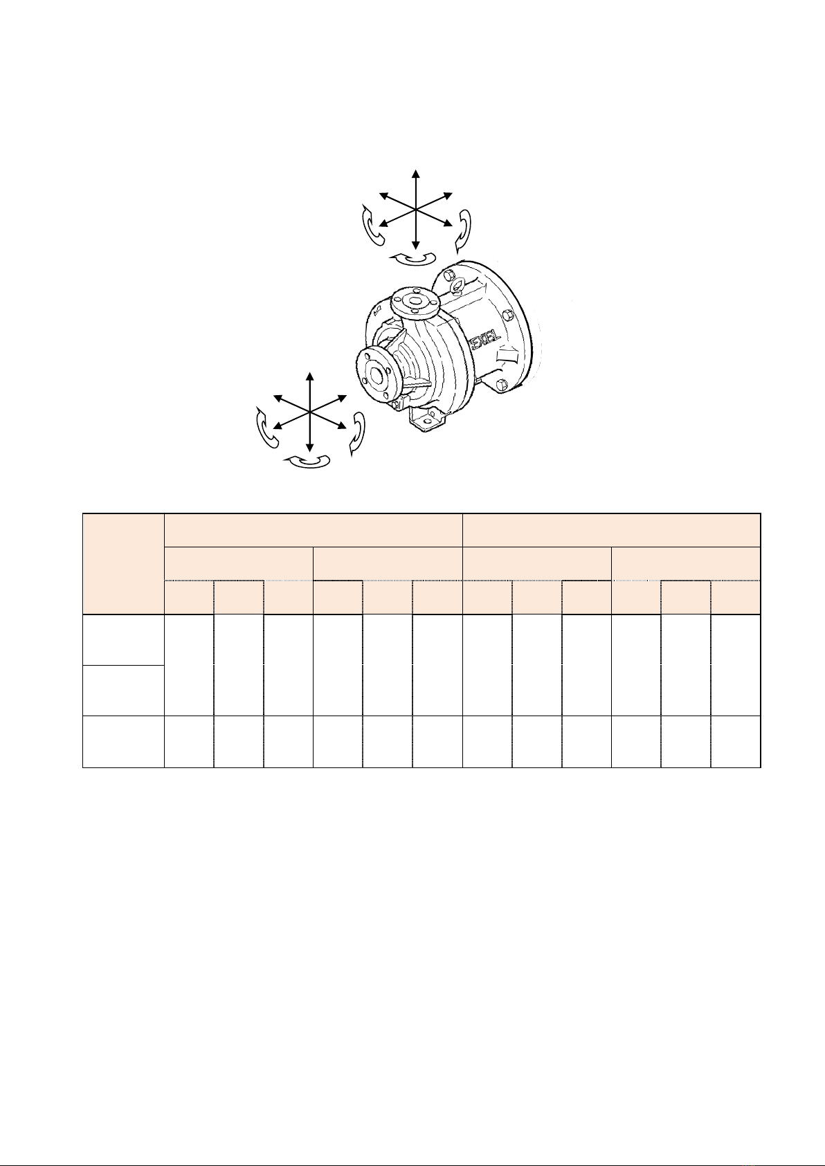
(3) All bolts and screws are securely fastened.
Looseness may occur during transportation, so be
sure to check the casing and drain bolts for looseness
before trial operation.
(4) The pump has no visible damage during the
transportation.
(5) Remove the motor fan cover and check that the motor
fan can be turned easily by hand. If the rotation seems
heavy or the fan does not turn, there may be some
internal damage. Contact the vendor or supplier
immediately.
2. Safety precautions
Like other high-speed or high-pressure machinery, a
magnetic drive pump can be very dangerous if it is not used
properly. Special attention is required if a corrosive or
hazardous chemical is used.
Instructions listed as "Warning" must be followed to avoid
property damages or fatal accidents.
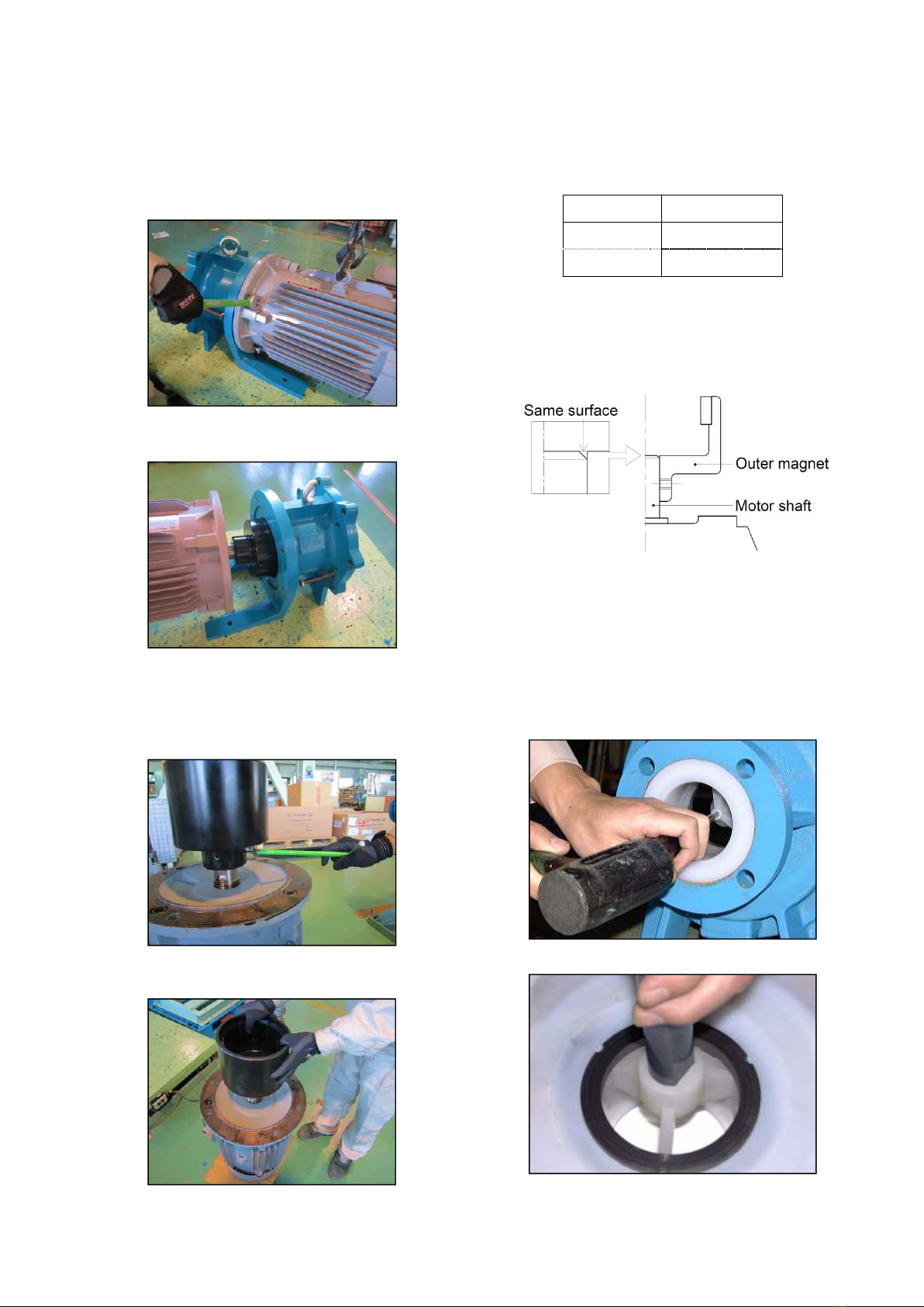
2.1. Transportation
The entire pump can be lifted using the eye-bolt provided on
the pump. However, ensure to secure the motor part with a
suspension rope (nylon sling) prior to the operation for
safety.
Warning
(1) An eye-bolt or a hooking hole provided on the motor
is rated only for the motor weight. Avoid suspending
the entire pump using the hooking hole on the motor.
(2) If a special base (not specified in the contract or listed
as standard) is set on the pump, do not suspend the
pump using the eye-bolt.
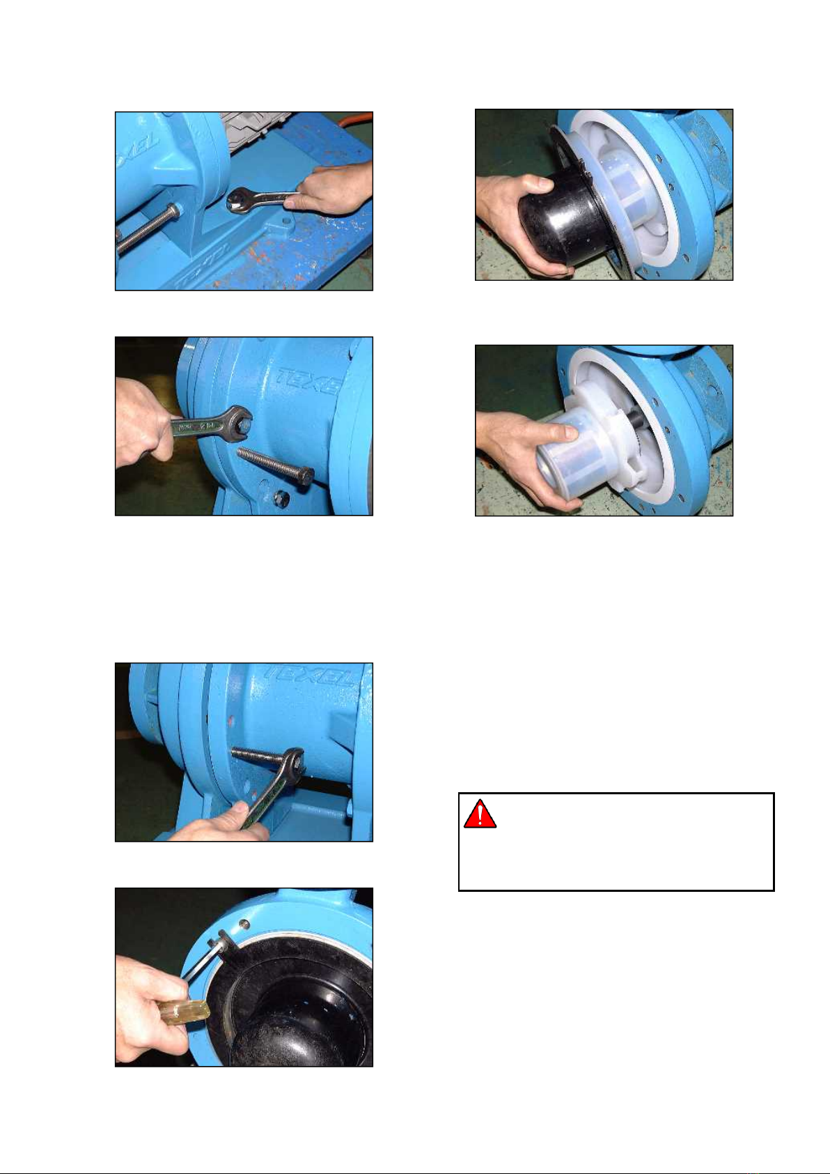
2.2. Confirmation
Before a test run after pump installation or a maintenance
work, make sure that all bolts including drain bolts and
casing bolts are securely fastened.
2.3. Application
The pump is designed and manufactured for the specific
application and specifications designated in the contract. If
the pump needs to be used for any other application, please
consult with the vendor or supplier prior to such use.
2.4. Alteration
Alterations to the pump carry a high degree of risk. It is not
the manufacturer’s responsibility for any failure or injury
resulting from alterations to the pump.
2.5. Ventilation
When handling chemical liquids that may generate harmful
gases, install safety equipment such as a ventilation system
in case of liquid leakage from the pump.
2.6. Qualified personnel only
The pump should be handled or operated by qualified
personnel with a full understanding of the pump. Any person
who is not familiar with the product should not take part in
the operation or management of the pump.
3. Storage
While in storage, perform maintenance and inspections by
following the instructions shown below until pump startup.
3.1.
Short-term storage (less than 3 months)
(1) Do not remove the bore seal.
(2) Store the pump in a well ventilated location without
humidity. Also ensure to avoid.
wind-blown rainwater, leak from the roof, pool of water, etc.
(3) Protect the cable holes on the motor terminal box with
a duct tape to close the gap and prevent dusts from
entering the box.
(4) Avoid a location where there is a potential risk of pump
damage due to surrounding equipments falling on the
pump or due to a contact with other devices being
transported. If it is not possible to avoid such locations,
provide sufficient protections for the pump.
(5) Do not place heavy objects on the pump.
(6) In winter, there is a possibility of dew condensation
and the dew being frozen inside the pump. Drain the
liquid to avoid this.
(7) In case a pump that had been used needs to be stored,
do the followings:
Clean the interior of the pump with fresh water.
Provide protections to the pump inlet and outlet to
prevent infiltration of foreign materials.
If the sum of initial operation period and the
storage period becomes longer than one year,
replace the gasket inspect the interior of the pump
before running it again.
3.2.
Long-term storage (more than 3 months)
(1) Follow instructions (1) through (7) for the short-term
storage stated above.
(2) Measure and record the insulation resistance at the
time of delivery and check it regularly as the insulator
of the motor may absorb moisture and the insulation
resistance may drop. If the insulation resistance is
dropped, dry the insulator following instructions from
the manufacturer and provide protection against
moisture. (Refer to the motor instruction manual.)
Warning
If the pump is run with poor insulation of the motor, a
leak of electricity or other accident may occur. Ensure
to check the insulation resistance regularly.
(3) Remove the motor fan cover once a month and turn
the motor fan manually.
(4) If the pump is run after a period of one year or longer,
ensure to replace the gasket with a new one.

- 3 -
4. Installation and Piping
Caution
Ensure protection and containment of solution in the
event of plumbing or pump damage. And, t
ake
appropriate spill protection measures to prevent spilled
liquid from draining directly to the ground.
Improve the drainage environment around the pump
installation so that the pump will not be submerged
due to the rain water.
4.1. Installation
(1) In principle, the pump should be installed on a
concrete foundation. If it is not possible, the pump may
be installed on a steel structure provided that the
vibration during operation is prevented.
(2) Insert the foundation bolt into a bolt hole on the pump
base or bracket, attach a nut tightly to the bolt head,
and suspend it inside the foundation bolt hole.
(3) In case of a concrete foundation, insert a wedge in
between the concrete and the base surfaces at four
locations and keep the pump level.
(4) To check the levelness, use a level gauge on the
upper surface of the pump outlet flange and check in
all directions.
(5) After checking the levelness, fill the gaps between the
concrete foundation and the base or the main unit with
a fine mortar, as well as gaps in the foundation bolt
holes. Ensure that everything is evenly bonded. (Fig.
4-1)
(6) Leave the pump as is for several days to let the mortar
harden. Then tighten the nut on the foundation bolt.
(7) In case the pump is installed on a steel structure, bolts
and nuts may be used but ensure to fasten them
tightly in a similar manner.
Fig.4-1
4.2. Piping
Prior to connecting piping, confirm that the bore seal has
been removed.
4.2.1. Piping load
(1) Support and secure pipes connected to the pump inlet
and outlet at a location close to the pump to avoid
undue load on the pump.
(2) In case metal pipes are used or the pipe length is long,
use flexible joints instead of connecting pipes directly.
(3) Limit the piping load on the pump within the maximum
Allowable load specified in [7. Allowable Piping Load].
4.2.2. Suction piping (Fig. 4-2 and 4-3)
(1) Make the suction piping as short as possible. However,
note that a valve and a short pipe (about 0.3m) must
be attached to facilitate disassembling of the pump.
(2) Make the flange joint portion of the suction piping as
little as possible.
(3) Since the suction piping will have a significant effect
on NPSHAV, give a thorough consideration on the pipe
diameter, length and attachments.
(4) Provide an upward gradient (approx. 1/50~1/100) on
the piping from the supply surface of fluid to the pump
to avoid air pocket. However, if the fluid is forced into
the pump, the gradient on the piping should be
downward toward the pump.
(5) Provide a dust screen on the supply tank.
(6) Ensure that the tip of the suction pipe is dipped
sufficiently deep into the fluid to avoid air to be sucked
in during the operation.
(7) Install the valve on the suction side with its handle
positioned horizontally as air pocket may be formed
while priming the pump.
(8) Limit the number of bends as little as possible and
avoid providing a bend close to the pump inlet.
(9) If a reducer is used, use an eccentric type to avoid air
pocket.
(10) If a concentric reducer is used, provide an air release
on the larger bore side. If multiple pumps are installed
for the same tank, provide an independent suction
piping for each pump.

- 4 -
4.2.3. Discharge piping
(1) Always provide a valve for the discharge piping.
(2) Since air pocket in the discharge piping may cause
harmful effect, provide an air release whenever
necessary.
(3) Even if the discharge piping is in the form of a siphon,
ensure to place the highest position below the
no-discharge water head.
(4) A check valve must be provided to prevent a back flow
at the time of stopping the pump or, in case the actual
water head is very high in order to prevent a water
hammer. However, since air can be entrapped below
the check valve at the start of the pump, provide an air
release. (Fig. 4-2)
4.2.4. Motor wiring
(1) Electrical works or wiring must be carried out by a
qualified and authorized person by local laws or
regulations.
(2) If the pump is installed outdoors, wiring must be
protected from rain water.
(3) Use the electromagnetic switch that conforms to motor
specifications such as voltage and capacity etc.
(4) Securely install the electromagnetic switch and
pushbutton switch away from the pump.
(5) Read the user’s manual for the motor thoroughly and
perform the work properly.
(6) As a preventive measure for electric leakage, install a
breaker and connect the ground wire.
(7) Take protective measures to prevent damage to the
power cable.
4.3. Protection
It is recommended to install the following monitoring
devices to prevent potential damages to the pump.
Integrating multiple methods of monitoring systems
increases effectiveness of protection against potential pump
damages.
(1) Pressure sensor
The sensor monitors the starting pressure and stops the
pump upon the detection of pressure change.
(2) Flow sensor
The sensor monitors the discharge flow and stops the pump
upon the detection of flow change.
(3) Level sensor
The sensor monitors the liquid level and stops the pump
when if falls below the specified level.
(4) Current sensor/Power sensor
The sensor monitors the motor load and stops the pump
upon the detection of load change.

- 5 -
Fig.4-2 Example of recommended piping
Fig.4-3 Suction piping
Status Correct Incorrect
Vertical
horizontal
bend
Inclined pipe
Eccentric
reducer
Installation
direction of
gate valve
①Gate valve
②Pipe support
③Vacuum gauge
④Flexible joint
⑤Pump
⑥Pressure gauge
⑦Check valve
⑧Air vent valve
⑨Air vent piping

- 6 -
5. Handling precautions
Caution
If the bearing material is SiC, confirm the rotational
direction after the priming or after removing the motor.
Even an instantaneous operation can cause damage.
5.1. Notes on the Start-up
(1) Remove the motor fan cover of the motor and confirm
that the motor fan can be turned easily.
(2) Clean the supply tank and suction pipes as trash
and/or scales that have entered the suction pipes
during the pipe installation can cause a fatal damage.
(3) Confirm the rotational direction of the motor. (The
direction is indicated on the casing.)
(4) Fully open the valve on the suction piping.
(5) Perform priming to fill the pump with the fluid
completely. Discharge air using the discharge piping,
etc. to perform priming. If it is difficult to discharge air,
turn the motor fan of the motor in the reverse direction
manually three to four times.
(6) Start the pump with the discharge valve completely
closed.
(7) If the pump is fully primed, the discharge pressure will
rise immediately. Then open the discharge valve
slowly and set the operational pressure or discharge
rate at a desired level.
5.2. Notes on the Operation
(1) Checking the Sound
Sucking in air or objects from the suction pipe often
cause an abnormal sound with vibrations. A fluctuation
of the needle on the suction gauge is often caused by
aeration.
(2) Checking the Vibration
A precaution is necessary for cavitation or vibration
due to faulty installation. Always adjust the discharge
rate using the discharge valve. Do not close the valve
on the suction piping.
(3) Checking the Operation status
Please use the specified discharge flow and head. Do
not use with extremely small or large discharge
amount. If operated below the minimum discharge flow,
the pump may be damaged due to insufficient
lubrication and cooling of bearings and sliding parts.
(4) Checking the Rotating direction of motor
Be sure to check the rotation direction of the motor.
(Clockwise direction from the motor fan)
If operated in reverse, pump may be damaged.
(5) Checking the Noise
The noise level of the pump will be from 60 to 90 dB (A
scale). However, it varies depending on the output and
type of the installed motor, installation and operating
status.
Provide a noise reduction cover if the pump noise
affects human bodies or compromises
communications to secure safety.
(6) Others
Pay attention to the discharge and suction pressure,
flow rate, electric current value, etc. An abnormal
fluctuation and/or a drop in these values often is a
result of a solid matter being stuck or air being sucked
in on the suction side.
Pump model Motor pole
Minimum flow
MTA-1516
MTA-1518
2 P 20 L/min
(5.3 GPM)
4 P 10 L/min
(2.7 GPM)
MTA-0326
2 P 50 L/min
(13.2 GPM)
4 P 30 L/min
(8 GPM)

- 7 -
5.3. Notes on the Stopping
(1) Normally, the pump should be stopped after
completely closing the discharge valve. Closing the
suction valve first may cause cavitation and may result
in a seizure.
(2) Slowly close the discharge valve. Quick closing of
valve may cause water hammer and pump damage.
(3) In case of flooded suction, close the suction valve after
stopping the operation.
(4) If the pump stops as a result of a power outage during
an operation, first turn off the power switch and, at the
same time, close the discharge valve manually.
5.4.
Notes on the Operational interruption
If the operation is interrupted for a prolonged period, drain
the pump. This is especially important in winter, when the
fluid inside the pump could freeze and the resulting
expansion of the liquid volume could cause a crack or
breakage of the piping.
5.5. Notes on the Motor
(1) For operation in explosive hazardous areas, the
maximum permissible temperature of the liquid in the
pump depends on the motor as well as the permissible
temperature class. In case a flange motor is used,
prohibit running the motor exceeding the maximum
allowable temperature for the shaft and the flange
specified by the supplier.
(2) The outer magnet is set on the motor shaft. For
disassembling/assembling, ensure to tighten the set
bolts for the motor shaft and outer magnet at our
specified standard torque.
5.6. Notes on the Ambient temperature
The allowable ambient temperature range is from 10 C to
40 C. (However, use the product under the normal room
temperature whenever possible.)
5.7. Notes on the Liquid
Caution
When high temperature liquid is transferred, pump
surface becomes very hot. Do not touch the pump or
pipe surface directly during or immediately after
operation. Take protective measure against burns.
When a harmful liquid as listed
below is used, be sure to
conduct daily inspection and
maintenance in order to
prevent liquid/gas leakage.
1. Explosive or flammable liquid
2. Corrosive chemicals
3. Harmful liquid or gas
(1) Ensure that there is no air bubbles in the liquid used. If
the air-containing operation is performed, the sliding
part will generate heat and the pump may be
damaged.
(2) If the specific gravity and viscosity of the liquid to be
handled are different from those of fresh water, the
shaft power, discharge rate and head will change. The
pump is manufactured according to the specifications
at the time of purchase. However, if you need to
change the planned specifications, please contact us.
(3) In principle, handling of slurry liquid is not possible.
However, under an agreement of the contract, SiC
bearing may be used depending on the type of liquid
used and operating conditions.
5.8. Others
(1) Run the auxiliary pump attached to the piping
periodically to confirm its readiness for operation.
(2) A no-load operation of the pump will cause a seizure of
the bearing and may result in a fatal accident and
therefore, must be avoided at all times.

- 8 -
6. Maintenance and Inspection
6.1. Construction and Parts name
6.1.1. Sectional drawing
No.
Parts Name Material Qty
Remark
No. Parts Name Material
Qty
Remark
001
Casing PFA+FCD450 1
Wet side: PFA
101-01
Casing gasket PTFE 1
013
Impeller PFA 1
※
2
101-05
Drain gasket PTFE 1
015
Shaft support PFA 1
104-01
Casing bolt SUS304
6
018
Shaft SiC 1
028
Bracket FC200 1
104-23
Motor bolt SUS304
4
051
Bushing C-PTFE/SiC 1
Carbon
104-33
Motor liner bolt SUS304
4
054
Front thrust ring
SiC 1
104-46
Outer magnet set screw
SCM 2
056
Rear thrust ring
SiC 1
104-52
Drain bolt SUS304
2
057
Outer magnet Rare earth 1
104-54
Rear casing bolt SUS304
4
058
Inner magnet Rare earth 1
※
2
104-58
Dis./Assembly bolt SUS304
2
059
Magnet lining PFA
060
Rear casing PFA+Eng.plastic
1
Wet side: PFA
901 Motor 1
102
Drain flange FC200 1
※
1
902 Motor liner SS400 1
105
Mouth ring C/G-PTFE 1
Carbon
/
SiC
(NOTE)
※1:The direction of drain depends on the model.
※2:Solid parts
The part names and part numbers shown in this manual may differ from the delivery specifications.

- 9 -
6.1.2. Exploded view

- 10 -
6.2. Maintenance and Inspection
In order to operate the pump smoothly, it is recommended
to implement a regular inspection program and keep the
record. Shown below are general points of maintenance.
6.2.1. Routine inspection
Perform the following inspection and record the results.
(1) The fluid level of the supply tank
(2) The suction and discharge pressure
(3) The current of the motor and the bearing temperature
(4) Abnormal noise and abnormal vibration
(5) Leaks on flanges and gasket
6.2.2. Regular inspection
Be careful in handling metals not to squeeze hands or
fingers since the outer and inner magnets are very strong
(magnetic force).
Also, be extra careful in handling the shaft, bearings, and
thrust rings as they have a potential risk of breakage and
may cause serious injuries.
6.2.3. Abrasive limit of the Bearing
Status A(mm)
B(mm)
C(mm)
At the time of
delivery 8.0 6.0 26.0
At the time of
replacement 7.0 5.0 27.0
Fig.6-1
Mouth ring Bearing
Components Inspection item Action/replacement timing
Casing
Accretion on the interface with the fluid Wash
Corrosion and swelling on the gasket Replace if faulty
Presence of cracks Check the cause if present
Presence of wears, rubbing, or cracks on the front thrust Check the cause if present
Impeller
Accretion on the blades, presence of foreign matters Wash
Trace of contact Check the cause if present
Wear on the mouth ring Check the cause if present
Inner magnet
Rubbing against the rear casing Check the cause if present
Presence of cracks on the edge and cylinder inner surfaces
Check the cause if present
Accretion on the interface with the fluid Wash
Wear on the bearing Check the cause if abnormal
Clogged cooling path on the bearing Wash
Rear casing
Rubbing against the inner magnet Check the cause if present
Accretion on the interface with the fluid Wash
Presence of wears, rubbing, or cracks on the rear thrust Check the cause if present
Shaft
Presence of cracks Check the cause if present
Wear on the bearing Check the cause if abnormal
Outer magnet
Rubbing against the rear casing Check the cause if present
Connection condition of the motor shaft, loose screws
Redo tightening at the proper
position
Motor bearing Presence of abnormal noise Once every two years (※)
※Follow the motor manual.

- 11 -
6.3. Disassembly & Assembly
Disassembly and assembly of the pump must be performed
following the instructions within the scope of this manual.
Do not disassemble anything beyond the point stated in this
manual.
Please be aware that if the product is disassembled or the
product is modified beyond the scope of the manual, the
product cannot be covered by the warranty and we will not
be liable for any accident or damage that may occur.
Ensure to have enough work space and work with safety in
mind.
Information
Pump parts, especially cast parts and electric motor
, are
very heavy and it is advisable to work with a chain block or
crane.
Information
The pump delivered may differ in appearance and shape
from the photos shown in this manual.
6.3.1. Notes on Disassembly
Warning
There is a danger of injury resulting from the human
body getting in contact with the chemical during or after
the disassembling operation.
If a finger gets caught in between the inner or outer
magnet and a metal when they attract each other,
it may
cause a serious injury can be expected.
The pump is a rotational machine and the worker may
suffer a serious injury if the power is turned on with
the
rotor exposed during the disassembling operation.
(1) Wear appropriate protective gears (rubber gloves,
protective goggles) before disassembling the pump.
(2) Be careful in handling the shaft and bearings as they
are vulnerable to physical damage.
(3) Since the inner and outer magnets are strongly
magnetized, pay attention to attraction of metallic
dusts and metallic items.
6.3.2. Preparation for Disassembly
(1) Ensure the safety of operation such as securing the
footing.
(2) Turn OFF the main power to prevent an accidental
operation of the motor and place a sign to clearly
indicate that a maintenance work is in progress so that
no one would turn on the power.
(3) Close the valves on the suction/discharge piping
completely and place a sign to clearly indicate that a
maintenance work is in progress so that no one would
release the valves.
(4) Drain liquid from the pump and piping using the drain
provided on the pump.
As for the procedures for draining, refer to the general
example explained below and give a thorough
consideration to the fluid and working environment involved.
1) Release the pump drain.
2) Loosen the bolts on the discharge side drain connection
slowly and evenly. If the fluid leaks from the drain during
this operation, wait for the fluid to stop and retreat to a
safe position until the fluid comes to a complete stop.
Warning
(1) If the bolts on the pump flange on the discharge
side were loosened quickly, the fluid may scatter
from the drain and cause a serious injury to the
worker.
(2) It is dangerous to stand in front of the drain during
the draining operation. Always check the standing
position while proceeding with the operation.
(5) Repeat the step 2) described above and confirm that
the drain operation is complete by lifting the piping with
a screwdriver or a similar tool when the bolts are
removed.
i
i

- 12 -
6.3.3. Disassembly
(1) Remove the bracket bolts (104-17).
Photo 6- 1
(2) Remove the casing bolts (104-01).
Photo 6- 2
(3) While the motor is in place, move the bracket (028)
backward until the rear casing (060) becomes visible.
In doing so, the bracket can be inched safely by
inserting casing bolts or assembling/disassembling
bolts into the left and right screw holes on the front
surface of the bracket and tightening them evenly. Use
this method if it is not possible to apply sufficient safety
measures.
Photo 6- 3
(4) Remove the rear casing bolts (104-54).
Photo 6- 4
(5) Remove the rear casing (060) by pulling it backward.
Photo 6- 5
(6) Also remove the inner magnet (058+059) and the
impeller (013) by pulling them backward.
Photo 6- 6
6.3.4. Assembly
For assembly of the pump, follow the disassembly
procedure in reverse order.
(1) Insert the motor (with outer magnet) into the bracket
(028) and secure it with motor bolts.
(2) Insert the inner magnet (with impeller) into the shaft of
the pump (018), set the casing gasket (101-01) on the
rear casing, fit the rear casing into the casing, and
secure it by tightening the rear casing bolts. (Hold the
tightening torque to the level of manual tightening.)
(3) Move the bracket forward and tighten the casing bolts
with a torque of 41 N・m (±3%) onto the casing. If
bolts such as assembly/disassembly bolts had been
used in disassembly, ensure to remove them here.
Warning
If a finger gets caught in between the inner/outer
magnet and a metal when they attract each other,
it
may cause a serious injury.
(4) Secure the bracket by tightening the bracket bolts.
(5) Upon completion of assembling, remove the motor fan
cover of the motor and confirm that the motor fan can
be turned easily by hand. If the motor fan does not turn
or its turn seems heavy, it will be necessary to
disassemble the pump and ensure to assemble it
properly.

- 13 -
6.3.5. Replacement of the Motor and the Outer
magnet
(1) For dismounting the motor from the bracket, hang the
motor by using an eyebolt equipped (or Nylon sling) on it for
the safety first.
(2) Remove the motor bolts (104-23) and possibly the
motor liner bolts (104-33) if there are.
Photo 6- 7
(3) Pull out the motor.
Photo 6- 8
(4) Place the motor upright on the floor with its motor fan
cover, which has been removed from the bracket,
facing down.
(5) Loosen the outer magnet set screws (104-46).
Photo 6- 9
(6) Pull out the outer magnet (057) from the motor shaft.
Photo 6- 10
(7) To install, insert the outer magnet (057) into the motor
shaft and tighten the outer magnet set screws
(104-46) observing the torque.
Screw size Torque (N・m)
M8 15(±3%)
M10 30(±3%)
While doing so, align the bottom of outer magnet and
the top of the motor shaft. (Fig. 6-2)
Fig.6-2
6.3.6. Replacement of the Shaft
Insert a Phillips screwdriver through the hole on the shaft
support section and, with the tip of the screwdriver touching
the shaft, tap on its head with a plastic hammer until the
shaft becomes free. To put back the shaft in place, align the
notch on the shaft support section and the shaft and then
tap on the shaft with a plastic hammer to insert it until it is
firmly in place.
Photo 6- 11
Photo 6- 12

- 14 -
6.3.7. Replacement of the Bearing
To remove the bearing, insert a round rod (of diameter
around 38 mm) from the impeller side and hammer the
bearing out little by little with a plastic hammer. To reinstall,
align the notch on the bearing and the inner magnet and tap
on the bearing with a plastic hammer to insert it slowly. In
doing so, cover the points of hammering with a cloth to
avoid damaging the bearing.
Photo 6- 13
6.3.8. Replacement of the Mouth ring and the
Front/Rear thrust ring
Since these parts are secured by holding tabs, melt those
holding tabs with a hot-air welder and raise them before
removing the parts. To set new parts, align the notch on
respective parts, melt the holding tabs with a hot-air welder,
and crush them with a round rod to secure the parts firmly.
Photo 6- 14
6.3.9. Replacement of the Shaft support
The MTA model is designed to allow replacement of the
shaft support, which holds the shaft. Since the shaft support
is welded onto the casing, the weld must be cut off with a
lathe or similar device to remove the shaft support. To
replace a new shaft support, check the orientation of the
reinforcement rib, insert the shaft support, and then weld
the entire circumference.
Note: This working should be suggested to ask the vendor
or supplier.
6.4. Placing Parts order
When placing parts order, please have the pump model,
serial number, parts name and ID number contact the
vendor or supplier. A nameplate is placed on the bracket.
Caution
Do not reuse damaged parts.
6.5. Repair
If any abnormality is found during use, immediately stop the
operation and investigate the cause.
(1) Please read this instruction manual and inspect it
again before requesting a repair.
(2) For repair requests, please contact the vendor or
supplier.
(3) When sending a pump, etc., be sure to thoroughly
wash it as it is dangerous if chemical liquid remains
inside.
(4) When requesting repairs, please inform us of the
following matters.
①Product type and serial number
②Failure location and its status
③Period of use and conditions of use (liquid name,
concentration, temperature, etc.)
6.6. Warranty period and Coverage
(1) Warranty period: One year from the date of delivery.
(2) Free repair: Within the warranty period, we will provide
free support for failures and damages caused by
defects in our design and manufacturing.
(3) Paid repair: Repairs for failures/damages due to the
following causes.
① Repair of products after warranty period has
expired.
② Repair of failures and damages caused by
incorrect handling.
③ Repair or modification by anyone other than us or
a person designated by us.
④ Use of parts other than those specified by us.
⑤ Damage due to disasters such as earthquakes
and fires and force majeure.
(4) If the product based on the standard or material
specified by the customer is broken or damaged, it is
not covered by the warranty.
(5) We are unable to compensate for various expenses
resulting from accidents of delivered products,
secondary damage such as damage to other
equipment, devices and equipment, and expenses
required for restoration.
6.7. Disposal of used pump and parts
Remove a chemical and flush it out before the pump is
disconnected from piping. Dispose of any used or damaged
pump in accordance with local rules and regulations. If
necessary, consult a licensed industrial waste disposal
company.

- 15 -
7. Allowable Piping Load
When connecting the pipes, the load and moment of the pipes applied to the pump should not exceed the values in the table
below.
MODEL
SUCTION DISCHARGE
FORCE (N) MOMENTS (N・m) FORCE (N) MOMENTS (N・m)
Fx Fy Fz Mx My Mz Fx Fy Fz Mx My Mz
MTA-1516
774 392 647 588 392 294 617 314 519 470 314 235
MTA-1518
MTA-0326
1588
794 1323
1205
804 608 1274
637 1058
960 647 490
Fy
Fx
My
Mx
Mz
Fz
Fy
Fx
My
Mx
Mz
F
z

- 16 -
8. Troubleshooting
8.1. Insufficient flow/Pressure
Low pumping capacity or pressure defect
Check rotation direction
Within - 6 meter Foreign matter clogs in impeller or
casing
The saturated steam pressure of liquid
is high
Clear clogging
Review / change specifications
Decline of suction liquid level
High resistance in the suction piping
Confirm and remove abnormalities in
the suction piping system
Clear clogging
Secure liquid supply and water level on
the suction side
Review / change piping equipment
Suction head is too much high
Foreign matter clogs in the suction
piping and or foot valve
Insufficient shut off pressure
Review of equipment
More than
- 6 meter
Inadequate air release
Stop the pump and
prime sufficiently
Wear inside the pump
Check presence of
foreign matter and remove
Check readouts on the
suction gauge
Head of the equipment
is too much high
Fully open discharge valve
Compare pump specifications
with gauge reading when pump is
in operation
Head is lower than
specified
Head is higher than
specified
Normal shut off pressure
Replace two of the three phases
Reverse rotationCorrect rotation
Check shut off pressure with
discharge valve fully closed

- 17 -
8.2. Pumping failure
Identify and improve the cause
Remove the cause
Clear clogging
Remove foreign matter
Replace magnet parts
Identify and improve the cause
Adjust suction water level
Identify and improve the cause
Clear clogging
Remove air pocket
Adjust suction water level
Identify and improve the cause
Ensure sufficient suction water
level
Review / improve piping system
Magnetic decoupling
Rotate motor fan manually
Light Heavy (or Lock)
Foreign matter clogs in impeller or
casing
Foreign matter clogs in impeller or
casing
The saturated steam pressure of liquid
is high
Air is sucked in from the end of the
suction piping
Air pocket in the suction piping
Within -6 meter
Remove foreign matter
Review specification
Impeller wear
Change parts
Magnetic force decrease due to
magnet corrosion
Contact between outer magnet and
rear casing
Clogging between rear casing and
inner magnet
Clogging from foreign matter causes
bushing to lock
Inadequate air release
Bleed the air
Sharp fall in discharge
pressure
Check readouts on the
suction gauge
Suction head is too much high
Foreign matter clogs in the suction
piping and or foot valve
Low suction liquid level
High resistance in the suction piping
More than -6 meter
Gradually open discharge
valve
Same pressure as shut off
pressure
Discharge/check valves do not open
due to defects
Suction head is too much high
Clogging in the discharge piping
There may be the air pocket in the
discharge piping
Leakage of foot valve ・ Water leak in the
middle of suction piping
Identification and improvement of the
cause
Priming impossible Priming normal
Check shut off pressure with discharge
valve closed
Normal shut off pressure Insufficient shut off pressure
Pumping failure
Correct rotation
Prime Replace two of the three phases
Reverse rotation
Check rotation direction

- 18 -
8.3. Vibration and Noise
Vibration and Noise
Check rotation direction
Correct rotation
Confirm where vibration and noise come
from
Reverse rotation
Replace two of the three phases
Loose outer magnet set screw
Bearing abnormality
Motor
Bearing parts wear
Damaged bearing parts
Incomplete foundation
Inside pump
Clogging of foreign matter in
pump
NormalAbnormal
Check vacuum on suction side
Inside foundation piping
Water hammer
Piping or foundation resonance
Loose mounting bolts
Cavitation
Tighten the screws
Replace parts
Replace parts
Replace parts
Ensure sufficient suction pressure
Identify the cause and remove
foreign matter
Improve driving operations
Improve piping
Tighten the bolts
Redo foundation

- 19 -
8.4. Over current
Normal Abnormal
Excess flow rate
Clogging from foreign
matter in pump
Damaged bearingDamaged motor
Over current
Check rotaion direction
Correct rotation Reverse rotation
Measure current with discharge valve fully
closed Replace two of the three phases
Repair/Replace motor
Manual rotation of the motor fan
(Heaby)
Manual rotation of the motor fan
(light)
Change in specific gravity of liquid
Stabilize specific gravity
Remove foreign matterReplace parts
Adjust flow rate
This manual suits for next models
2
Table of contents
Other TEXEL Water Pump manuals
Popular Water Pump manuals by other brands

Zoeller
Zoeller 1461-0006 manual

AST
AST SOC GMP-050 Series instruction manual

Bestway
Bestway Built-in Sidewinder P3150 owner's manual

Homa
Homa Saniboy G 180-16W Original instruction manual

Gardena
Gardena PTU 3700/4 Operator's manual

GORMAN-RUPP
GORMAN-RUPP 02F1-GL Application, Installation, Operation, and Maintenance Manual

Ebsray
Ebsray RC SERIES Installation, operation & maintenance instructions

IWAKI AMERICA
IWAKI AMERICA MD SERIES instruction manual

Advantage Controls
Advantage Controls MicroTron O Series manual

Waspper
Waspper WP20CH/P instruction manual

Kremlin-Rexson
Kremlin-Rexson AIRMIX 08-120 Disassembly/Reassembly

Nakayama
Nakayama PRO NP1070 manual