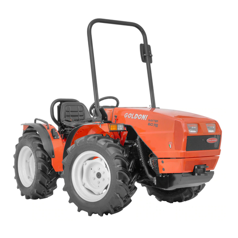
Textron Ransomes CT435 Specifications

Ransomes Way, Ipswich, England, IP3 9QG
RANSOMES
CT435 COMPACT TRACTOR
GB
OPERATORS INSTRUCTIONS
Publication No. 24080G (rev.1) (RSJ 001 101997)


1
PLEASEREADCAREFULLY:
Foracompletelistofthepre-deliveryservicechecksperformedby your dealer, refer to PRE-DELIVERYSERVICEon the upper portion of page
61and 63. The copy on page 61 is your record of the serviceperformed,andthe copy on page 63, which is to be removed from the manual, is
your dealer’s. MAKE SURETHAT YOUAND THE DEALER SIGN BOTH COPIES.
Afteryou have operated your tractorforfiftyhours,takethis manual and your tractortoyour dealer.Hewill then perform thefactory recommended
50-HOURSERVICEaslistedonthelowerportionsofpages61and63-withoutcharge - except for lubricant, oil, or filters replaced as part of
normal maintenance. MAKE SURE THATYOUANDTHE DEALER SIGN BOTH COPIES.
APRODUCTIDENTIFICATIONPLATEislocatedonthe left-hand side of the transmission housing. The numbers on the plate are important
shouldyour tractor requirefutureservice. For your convenience,haveyour dealer recordthenumbers in the appropriatespacesbelow.
RANSOMESpolicy is one of continuous improvement, andtheright to change prices, specification or equipmentatanytime without notice is
reserved.
Alldata given in thisbookis subject to production variations.Dimensionsand weights are approximate onlyand the illustrations donotnecessarily
showtractors in standardcondition. For exact informationaboutany particulartractorplease consult your RANSOMESTractorDealer.

2
INTERNATIONAL SYMBOLS ..................................................................................3
SAFETY PRECAUTIONS ...................................................................................... 4-5
CONTROLS AND INSTRUMENTS....................................................................... 6-13
SEAT AND ROPS ....................................................................................................6
LIGHTING ................................................................................................................7
INSTRUMENT PANEL ........................................................................................... 7-9
THROTTLE CONTROLS .........................................................................................9
BRAKE CONTROLS ...............................................................................................10
DIFFERENTIAL CONTROL ....................................................................................10
TRANSMISSION AND PTO CONTROLS............................................................ 10-12
HYDRAULIC LIFT SYSTEM CONTROLS ........................................................... 12-13
OPERATION ........................................................................................................ 14-31
BREAK-IN PROCEDURES .....................................................................................14
STARTING THE ENGINE .................................................................................... 14-15
STOPPING THE ENGINE ......................................................................................15
OPERATING THE TRANSMISSIONS,
FOUR-WHEEL DRIVE AND PTO........................................................................ 15-18
TOWINGTHETRACTOR.........................................................................................18
OPERATING THE DIFFERENTIAL LOCK .......................................................... 18-19
OPERATING THE HYDRAULIC LIFT SYSTEM .................................................. 19-22
DRIVING THE TRACTOR.................................................................................... 22-24
WHEEL TREAD SETTINGS................................................................................ 24-27
TRACTOR WEIGHTING...................................................................................... 28-29
TYRE PRESSURES ............................................................................................ 30-31
LUBRICATION AND MAINTENANCE.................................................................. 32-55
LUBRICATION AND MAINTENANCE CHART .................................................... 32-33
FUEL AND LUBRICANTS.................................................................................... 34-37
FUEL AND LUBRICANT SERVICE PROCEDURES ........................................... 37-42
GENERAL MAINTENANCE ................................................................................. 42-53
TRACTOR STORAGE ......................................................................................... 53-54
GENERAL TORQUE SPECIFICATION TABLE ......................................................55
SPECIFICATIONS ............................................................................................... 56-60
SAFETY DECALS AND INSTRUCTION DECALS .............................................. 61-66
PREDELIVERY AND 50-HOUR SERVICE .......................................................... 69-71
CONTENTS

3
INTERNATIONAL SYMBOLS
Asa guide to the operation ofyourtractor,
variousinternational symbolshave been
utilisedon the instruments and controls.
Thesymbols are shown belowwithan
indicationof their meaning.
Enginespeed
Hoursrecorded
Enginewater
temperature
Airfilter
Engineoil
pressure
Hazardwarning
Axleconnect
Axledisconnect
Continuously
variable
Increase
Decrease
Fuellevel
Creeperrange
High range
Middlerange
Lowrange
Neutral
Dieselfuel
Glow
Enginestop
Engineoil
Parkingbrake
Lights(upper
beam)
Lights(lower
beam)
Lock
Releaselock
Up
Down
Differentiallock
Readoperator’s
manual
Battery
Powertake-off
(on)
Powertake-off
(off)
“Tortoise,” slow or
minimumsetting
“Hare,”fast or
maximumsetting
Warning
Controllever
operating
direction
Rockshaft
(raised)
Rockshaft
(lowered)
Remotecylinder
(float)
Remotecylinder
(retracted)
Remotecylinder
(extended)
Forward
Warning!
contains
asbestos

4
pressurisinglines.
Iffluid is injected into the skin, obtain medical attention
immediatelyor gangrenemay result.
7. Donotmodifyor alter or permit anyone elsetomodify or
alterthis tractor or any of its components or any tractor
function
withoutfirst consulting RANSOMESTractor Dealer.
8. Thefuel oil in the injection system is under highpressure
andcan penetrate the skin.Unqualifiedpersons should not
removeor attempt toadjusta pump, injector, nozzle orany
otherpart of the fuel injection system.Failureto follow these
instructionscan result in serious injury.
9. continuouslongtermcontact with used engine oilmay
causeskin cancer.Avoid prolonged contact with used
engineoil. wash skin promptlywith soap and water.
10. Somecomponentsonyour tractor,such as gasketsand
frictionsurfaces (brake linings, clutch linings etc.), may
containasbestos. Breathing asbestos dust isdangerousto
yourhealth.Youare thereforeadvisedto haveany
maintenanceof repair operationson such components
carriedout by an authorised SHIBAUARATractor Dealer. If
however,serviceoperations are tobe undertakenon parts
thatcontain asbestos, theessentialprecautions listed below
mustbe observed:
• Work out of doors orinawell ventilated area.
•. Dustfoundonthe tractor or produced during work on the
tractorshould be removedby extraction notbyblowing.
• Dustwaste should be dampened,placedin a sealed
containerand marked toensuresafe disposal.
• Ifany cutting, drilling, etc., is attempted onmaterials
containingasbestos, the itemshould be dampened andonly
handtools or low speedpower tools used.
OPERATING THE TRACTOR
1. Applythe parkingbrake, place theP.T.O. lever in the “OFF”
position,the lift control lever inthe down position, the remote
controlvalve levers intheneutral position, andthe
transmissionin neutral before startingthe tractor.
2. Donotstartthe engine or operate controlswhilestanding
besidethe tractor.Always sit in the tractor seat when
startingthe engine oroperatingcontrols.
3. Donot bypasstheneutral start switches. consult your
RANSOMESTractor Dealer if your neutral start controls
malfunction.Use jumper cables onlyin the recommended
manner.Improperuse can result intractorrunaway.
4. Avoid accidental contactwith thegearshiftlevers while the
engineis running. Unexpectedtractormovement can result
fromsuch contact.
5. Donot get offthe tractor while it is in motion.
6. DisengagePTO,shut offthe engineandapplythe parking
brakebefore getting off the tractor.
7. Donot parkthetractoron a steep incline.
8. Donotoperatethe tractor engine inanenclosed building
withoutadequate ventilation.Exhaustfumes cancause
death.
9. Ifpowersteeringor engine ceases operating,stopthe
tractorimmediately.
10. Pullonlyfrom the drawbar or the lowerlinkdrawbar in the
downposition. Use only a drawbar pinthatlocks in place.
Pullingfrom the tractorrearaxle or any pointabovethe axle
maycause the tractor to upset.
SAFETY PRECAUTIONS
Thefollowing precautions aresuggestedto help prevent accidents.
Acareful operator is the best operator. Most accidentscanbe
avoidedby observingcertainprecautions. Readandtake the
followingprecautions before operatingthistractor to helpprevent
accidents.Equipment should beoperatedonly by thosewhoare
responsibleand instructed to do so.
THE TRACTOR
1. ReadtheOperator’sManualcarefully before using the
tractor.Lackof operating knowledge canleadto accidents.
2. Ensurethatanyattached equipment or accessoriesare
correctlyinstalled,are approved for use withthetractor,do
notoverload thetractorand are operatedand maintained in
accordancewith the instructions issued bytheequipment or
accessorymanufacturer.
3. UseanapprovedRoll bar and Seat Beltforsafe operation.
Overturninga tractor without a roll bar can resultindeathor
injury.Ifyourtractor is not equipped with a roll bar and seat
belt,see your RANSOMESTractor Dealer. Always use the
seatbelt. Do not use the seat belt if the roll bar has been
removedfrom the tractor.
4. Ifa front end loader is to be installed, always useaFOPS
canopyto avoid injury fromfallingobjects.
5. Usethe handholdsandstep plates when getting on and off
thetractor to prevent falls. Keepstepsand platform cleared
ofmud and debris.
6. Donotpermitanyone but the operator torideon the tractor.
Thereis no safe place for extra riders.
7. Rememberthatyourtractor,ifabusedor incorrectly used,
canbe dangerous and becomea hazard to boththe
operatorand bystanders. Donotoverload or operatewith
attachedequipment which is unsafe, notdesignedfor the
particulartasks or is poorlymaintained.
8. Replaceallmissing,illegible, or damaged safetydecals.
Seelist of decals on page 53.
9. Keepsafety decalscleanof dirt and grime.
SERVICING THE TRACTOR
1. Thecooling systemoperatesunder pressure which is
controlledby the radiator cap.Itis dangerous to removethe
capwhile system is hot. Always turn cap slowly to the first
stopand allow thepressureto escape before removingthe
capentirely.
2. Donotsmokewhile refuelling the tractor. Keep anytypeof
openflame away. wait for engineto cool before refuelling.
3. Keepthetractorand equipment, particularlybrakesand
steering,maintained in areliableand satisfactory condition
toensure your safetyandcomply with legalrequirements.
4. Keepopenflameaway from batteryorcold weather starting
aidsto prevent fires or explosions.Usejumpercables
accordingto instructions to prevent sparks which could
causeexplosion.
5. Stoptheenginebefore performing anyserviceon the
tractor.
6. Escapinghydraulic/dieselfluidunderpressure can
penetratethe skin causing seriousinjury.
• DoNOT use your hand to check for leaks. Use a piece of
cardboardor paper to search forleaks.
• Stopengine and relievepressurebefore connecting or
disconnectinglines.
• tightenall connections beforestartingengine or

5
SAFETY PRECAUTIONS
SAFETY PRECAUTIONS (Continued)
11. If the front end of the tractor tends to rise when heavy
implementsare attached to thethree-pointhitch, install front
endor front wheel weights. Donotoperate the tractor with a
lightfront end.
12. Alwayssetthe hydraulic selector leverinposition control
whenattaching equipmentandwhen transporting
equipment.Be sure hydrauliccouplersare properly
mountedand will disconnect safely in caseofaccidental
detachmentof implement.
13. Donotleave equipment intheraised position.
DRIVING THE TRACTOR
1. watchwhereyouare going especially atrow ends, on roads,
aroundtrees and lowhanging obstacles.
2. To avoid upsetsdrive the tractor with care and atspeeds
compatiblewithsafety,especially whenoperatingover rough
ground,when crossing ditches or slopes, and whenturning
corners.
3. Locktractorbrakepedals together whentransportingon
roadsto providetwowheel braking.
4. Keepthetractorin the same gear whengoingdownhill as
usedwhen going uphill. Do not coastorfree wheel down
hills.
5. Anytowedvehiclewhose total weightexceeds that of the
towingtractor must be equipped with brakesforsafe
operation.
6. whenthe tractor is stuck ortiresarefrozentothe ground,
backup the tractor to prevent upset.
7. Alwayscheckoverhead clearance, especiallywhen
transportingthe tractor.
8. Whenoperating atnight,adjust lights to prevent blinding an
oncomingdriver.
OPERATING THE PTO
1. Whenoperating P.T.O driven equipment, shut offthe engine
andwait until the P.T.O. stopsbefore getting off the tractor
anddisconnecting theequipment.
2. Donotwearloose clothing whenoperating the power
takeoff,orwhen near rotating equipment.
3. WhenoperatingstationaryP.T.O.drivenequipment, always
placeboth gear shift levers inneutral,applythe tractor
parkingbrake and block the rearwheelsfront and back.
4. To avoid injury,donot clean, adjust, unclog or service P.T.O.
drivenequipment when thetractorengine is running.
5. Makesure the P.T.O. master shield is installed at all times
andalways replace the P.T.O.shieldcapwhen the P.T.O. is
notin use.
DIESEL FUEL
1. Undernocircumstancesshould gasoline, alcohol or
blendedfuels be added todieselfuel. These combinations
cancreate an increased fireorexplosive hazard. Such
blendsare more explosivethanpure gasoline inaclosed
containersuch as a fuel tank. Do not use these blends.
2. Neverremovethefuel cap or refuel withtheengine running
orhot.
3. Donotsmokewhile refuelling or when standingnearfuel.
4. Maintaincontrol ofthefuel filler pipe nozzle when filling the
tank.
5. Donot fill the fuel tank to capacity.Allowroom for
expansion.
6. Wipeupspilled fuel immediately.
7. Alwaystightenthefuel tankcap securely.
8. Ifthe original fuel tank cap is lost, replace it with a
RANSOMESapproved cap.Anon-approved, proprietary
capmay not be safe.
9. Keepequipmentclean andproperlymaintained.
10. Donotdrive equipment near openfires.
11. Neverusefuel for cleaning purposes.
12. Arrangefuelpurchases so that summer grade fuels are not
heldover and used in thewinter.
SAFETY FRAME (ROPS)
IfyourRANSOMESTractor is equipped with a safety frame it must
bemaintained in aserviceablecondition. Be carefulwhendriving
throughdoorways or workinginconfined spaces withlowheadroom.
Underno circumstances:
1. .. . . modify, drill or alter the safety frame in any way as
doingso could renderyouliable to legal prosecution.
2. .. . . attempt to straighten orweldanypartofthemainframe
orretainingbracketswhichhave suffered damage. By doing
soyou may weakenthe structure andendangeryour safety.
3. .. . . secure any parts on the main frame or attach your
safetyframe with other than the specialhightensile bolts
andnuts specified.
4. .. . . attach chains or ropes to the main frame for pulling
purposes.
5. .. ..takeunnecessary risks even though your safety frame
affords you themaximumprotection possible.
5
When you See this symbol it means: ATTENTION! BECOME ALERT! YOUR SAFETY IS Involved!

6
CONTROLS AND INSTRUMENTS
SEAT AND ROPS
TRACTOR SEAT
Your RANSOMES Tractor is equipped with a
suspension seat as shown in Figure 1. The seat is
adjustable to obtain the most comfortable position.
To move the seat fore and aft, move the seat
release lever to the right and slide the seat fore and
aft as desired, Figure 2.
To adjust the seat for flotation, turn the flotation
adjusting bolt right for a firm ride, or left for a soft
ride, Figure 2.
Figure 1 - Tractor Seat and ROPS
Figure 2 - Tractor Seat Adjustment
ROLLOVER PROTECTIVE STRUCTURE (ROPS)
A Roll Over Protective Structure (ROPS) are
optional equipment for this tractor at time of factory
assembly. If the ROPS was deleted by the original
purchaser or has been removed, it is recommended
that you equip your tractor with a Roll Over
Protective Structure (ROPS). ROPS are effective in
reducing injuries during tractor over-turn accidents.
Overturning tractor without a ROPS can result in
serious injury or death.
Roll Over Protective Structure (ROPS) are available
from your RANSOMES Tractor Dealer.
The safety offered by the roll bar is minimised.
WARNING: DO NOT attach chains or
ropes to the roll bar for pulling purposes
poses since the tractor can tip
backward. Always pull from the tractor
drawbar. Be careful when driving
through door openings or under low
overhead objects. Make sure there is
sufficient overhead clearance for the
roll bar.

7
CONTROLS AND INSTRUMENTS
LIGHTING
FLASHER WARNING LAMP
Your RANSOMES tractor is equipped with flasher
warning lights, Figure 3. The switch, Figure 4 for the
warning lights is located on the instrument panel.
Figure 3 - Flasher Warning andTail Lamp
The light switch must be turned to one of the “ON”
positions before the flasher will operate. For your
protection, use the safety flasher lights when
travelling on public roads, day or night.
LIGHT SWITCH
The light switch, shown in Figure 4, is a pull type
switch. lts positions are
1 st position OFF”
2nd position Tail Lamp “ON”
3rd position Headlights (Low Beam), and Tail Lamp
“ON”
4th position Headlights (High Beam), and Tail Lamp
“ON”
Figure 4 - Light Switch
INSTRUMENT PANEL
KEY SWITCH
The key switch is shown in Figure 5. Turning the
‘key to the left will activate the cold-start aid.
Turning the key to the right to the “on” position will
activate the warning lights and instruments. Turning
mg the key further right to the “start” position will
start the engine. Upon release, the key will spring
return to the “on” position.
Figure 5 - Instrument Panel
The starting circuit can only be activated when the
clutch pedal is. fully depressed and P.T.O. control
lever and MID P.T.O. control lever (if equipped) are
in the “OFF” position. Always check to make certain
the transmission main shift lever and P.T.O. levers
are in neutral before attempting to start the engine.
Refer to page 1 4 for complete starting instructions.

8
CONTROLS AND INSTRUMENTS
FUEL GAUGE
The fuel gauge is shown in Figure 5 and 6. The
needle indicates the amount of fuel in the tank.
Figure 6 - Temperature Gauge and Fuel Gauge
FUEL SHUTOFF VALVE
The fuel shutoff valve is shown in Figure 7. To open
the fuel shutoff valve, move the handle so
Figure 7 - Fuel Shutoff Valve
that it points straight up and down. To close the fuel
shutoff valve, move the handle to the horizontal
position. Always shut off the valve ‘A/hen servicing
any portion of the fuel system.
WARNING LIGHTS
The engine oil pressure, charge indicator, glow plug
indicator and air cleaner warning lights are located
as shown in Figure 5. When the key switch is turned
“ON” these lights will come on. After the engine has
been started, the lights should go out within a few
seconds. If they do not go out:
• Engine oil pressure warning light : Stop the
engine immediately and investigate the
cause. It is important to remember that this
light indicates oil pressure only. The operator
must regularly check the crankcase for proper
oil level.
• Charge indicator warning light : This is an
indication that the charging system is not
operating normally. Investigate the cause as
soon as possible, otherwise the battery will
become fully discharged.
• The glow plug indicator warning light : This
light comes on when turning the key switch to
the “HEAT” position and “START” position.
Refer to page 14 for starting engine
information.
• Coolant warning light: If the light comes on,
check the coolant level in the coolant reserior.
Add coolant so the level is between FULL and
LOW marks on the side of the reseroir.
• Air cleaner warning light : This is an
indication that the air cleaner element is
clogged. Disassemble the air cleaner, and
clean. Refer to page 40.
• Parking brake warning light: This light comes
on only when the parking brake is applied.
Release the parking brake before moving the
tractor.
NOTE: Make certain that all warning lights turn on
for a moment when turning the key switch to the
“START” position. If one of the warning lights does
not turn on, the bulb should be replaced.
PROOF-METER
The Proof-Meter is located on the right side of the
instrument panel, Figure 5 The Proof-Meter
indicates:

9
CONTROLS AND INSTRUMENTS
• The hours and portions of hours your tractor
has operated, based on an average engine
speed of 1867 rpm. Engine speeds below 1
867 rpm accumulate engine hours at a slower
rate than clock hours. Engine speeds above 1
867 rpm accumulate engine hours faster than
clock hours. Use the Proof-Meter as a guide
to determine hourly service and maintenance
intervals.
• Use the engine revolution per minute on the
Proof-Meter when operating P. 1. 0. driven
equipment. P.1. 0. -driven equipment must be
operated at an engine speed not to exceed
2238 rpm as shown by the P.1.0. symbol on
the rpm scale. Additional information on
P.T.O. operation can be found on page 18.
Ground speeds are indicated on a decal attached to
the top of the left fender. Additional ground
information can be found on page 60.
TEMPERATURE GAUGE
The engine coolant temperature gauge is shown in
Figure 6. When the needle is in the middle area, the
engine is at its normal operating temperature. The
needle at the “red” end indicates an overheated
engine.
WARNING: When engine is at
operatingtemperature alwaysrelieve
pressure in the cooling system before
removingthe radiator cap.
THROTTLE CONTROLS
HAND THROTTLE AND ENGINE STOP
CONTROL
The hand throttle is shown in Figure 8 Push the
throttle forward to increase engine rpm. Pull the
throttle rearward to decrease engine rpm. Turning
the key switch to the “OFF” position stops the
engine.
Figure 8 - Hand Throttle
FOOT THROTTLE
The foot throttle, shown in Figure 9, can be used
separately, or in conjunction with the hand throttle
With the hand throttle control lever set at selected
engine rpm, the foot throttle can be used to increase
engine rpm to its maximum speed Upon release of
the foot throttle, the engine speed will return to the
rpm at which the hand( throttle has been set.
Figure 9 - Foot Throttle and Brake Control

10
CONTROLS AND INSTRUMENTS
BRAKE CONTROLS
BRAKE PEDALS
The brake pedals are shown in Figure 9. The right
brake pedal is used to brake the right rear wheel.
The left pedal is used to brake the left rear wheel.
Depress both pedals simultaneously to stop the
tractor.
To assist in making sharp turns at slow speed,
depress the right or left brake pedals as required.
WARNING: When operating the tractor
at high speeds, never attempt to make
sharpturns by usingthe brakes.
BRAKE PEDAL LOCK
The brake pedal lock, shown in Figure 9, is used to
secure the brake pedals together. Lock the pedals
together whenever the tractor is operated at high
speeds and at any time the tractor is used on the
highway.
PARKING BRAKE
A convntional handbrake lever coupled to the
footbrake linkage is installed to the left of the drivers
seat. To apply the handbrake, pull the lever up. To
release, ease the lever up further, depress the button
on the end and lower the lever. Figure 13.
IMPORTANT: Ensure the handbrake is fully released
beforedriving off.
DIFFERENTIAL CONTROL
DIFFERENTIAL LOCK PEDAL
The differential lock pedal is shown in Figure 10.
Depressing the pedal locks the rear axle shafts
together, providing additional traction in wet or loose
soil. Refer to page 18 for differential lock operating
information.
WARNING: Tractor is very difficult to
steerwith differentiallocked.
Figure 10 Differential Lock Pedal
TRANSMISSION AND PTO CONTROLS
12 x 4 TRANSMISSION GEARSHIFT LEVERS
Thetransmission main shiftlever is shown in
Figure 11 -Transmission Controls

11
CONTROLS AND INSTRUMENTS
Figure 11. A diagram showing the shift pattern is
shown on the bezel around the gear shift lever.
Range selector is located at the left-hand side of the
seat, Figure 11. Three forward and one reverse
speed are provided for each of the three ranges.
This provides a total of 12 forward and 4 reverse
speeds.
SYNCHROMESH SHUTTLE TRANSMISSION
GEARSHIFT LEVERS (OPTIONAL)
Your RANSOMES Tractor is equipped with the
shuttle shift lever, shown in the Figure 12, which is
used to travel forward or rearward. The transmission
main shift lever is shown in Figure 12. A diagram
showing the shift pattern is provided on the bezel
around the gear shift lever. Range selector level is
located at the left-hand of the seat, Figure 1 2
Figure 12 - Synchromesh Transmission Controls
Four speeds are provided for each of the three
ranges. This provides a total of 12 forward and 12
reverse speeds.
CREEPER RANGE (ACCESSORY)
A creeper range accessory with a 1 2.29 : 1 ratio is
available which provides an additional 1 2 forward
and 4 reverse speeds or a total of 24 forward and 8
reverse speeds. The creeper range accessory of
synchromesh transmission provides an additional 1
2 forward and 1 2 reverse speeds or a total of 24
forward and 24 reverse speeds. The control is
located on the left-hand front of the rear-axle centre
housing, Figure 13, below the range selector lever.
Full upward movement of the lever engages the
creeper range. Full downward movement
disengages it.
FOUR-WHEEL DRIVE
The shift lever for the four-wheel drive is located on
the right-hand and below the seat, Figure 13. Full
downward on the lever disengages the four-wheel
drive (OFF). Full upward engages the four-wheel
drive (ON).
Figure 13 - Four-Wheel Drive Lever
CLUTCH PEDAL
The foot operated clutch pedal, Figure 14, must be
completely depressed to stop forward travel and P.1.
0. shaft rotation. Always fully depress the pedal
when changing gear ratios or engaging four-wheel
drive or creeper range.

12
CONTROLS AND INSTRUMENTS
Figure 14- Clutch Control
DUAL CLUTCH
The dual clutch allows stopping tractor movement
while the P. T. 0. shaft continues rotation.
When the clutch pedal is depressed to position (1),
Figure ‘1 5’ the tractor movement stops while the
P.T.O. shaft continues rotation (if the P. T.O. is
engaged). If the pedal is depressed completely (2),
both tractor and P. T. 0. motion stop.
Figure 15 - Dual Clutch
NOTE: The clutch pedal is equipped with an
alternate pedal stop. When engaged the alternate
stop prevents the pedal from being depressed into
the P. T. 0. disengaged position. The alternate stop
is intended to provide more convenient operation
during uses such as loader operation, that do not
require use of the P. T. 0. system.
WARNING: The P. T. 0. system cannot
be disengaged with the alternate clutch
pedal stop. DO NOT engage the
alternate STOP with the P. T. 0. control
lever in the on position. Never attempt
to operate P. T. 0. driven equipment
with the alternate stop engaged.
TRANSMISSION P. T. 0. CONTROL LEVER
The transmission P. T. 0. control lever is shown in
Figure 1 6 The lever engages and disengages the P.
T. 0. If the tractor engine is running, always depress
the clutch pedal fully before moving the lever. Move
the lever forward to engage the P. T. 0. and
rearward to disengage the P.T 0.
Figure 16 - P. T. 0. Control
HYDRAULIC LIFT SYSTEM CONTROLS
HYDRAULIC LIFT CONTROL LEVER
The hydraulic lift control lever is shown in Figure
1 7. The lever is located at the right hand side of

13
CONTROLS AND INSTRUMENTS
the seat. To lower the lift arms, push the lever
forward. The adjustable stop is provided for
returning the lever to a preset position in the
quadrant. To raise the lift arms, pull the lever
rearward. The flow control valve must be opened
before the hydraulic lift control will function.
Figure 17 - Hydraulic Lift System Control
FLOW CONTROL VALVE
The flow control valve is shown in Figure 18.
Turning the valve “in” (clockwise) will decrease the
lowering speed of the lower links, and turning the
valve “out” (counterclockwise) will increase the
lowering speed of the lower links. Refer to “FLOW
CONTROL,” page 21 , for additional information on
operating the flow control valve.
Figure 18 - Hydraulic Flow Control Valve
DRAFT AND POSITION CONTROL LEVERS
(OPTIONAL)
The hydraulic lift control levers are shown in Figure
1 9 The levers are located at the right hand side of
the seat. The outer lever is position control lever,
the inner lever is the draft control lever. The position
control lever is used to raise or lower the hydraulic
lift arms. To raise the lift arms, pull the lever
upward. To lower the lift arms, push the lever
downward. The adjustable stop is provided for
locating the lever at any position in the quadrant.
The draft control lever is used to adjust sensitivity to
draft loads. For light draft loads the lever is moved
forward, and for heavy draft loads the lever is pulled
rearward.
Figure 19 - Hydraulic Lift System Control -Draft
and Position Control (Optional)
REMOTE CONTROL VALVES - OPTIONAL
Two types of remote control valves are available for
your RANSOMES Tractor. A single or double spool
valve is available to operate one or two remote
cylinders for front and rear-mounted implements.
Refer to page 21 for operating instructions.
HYDRAULIC MANIFOLD BLOCK
Your RANSOMES Tractor is equipped with a
hydraulic manifold block, which can be utilized to
supply oil to hydraulic equipment such as a front
loader, dozer blade, etc.
Refer to “OPERATING HYDRAULIC MANIFOLD
BLOCK” on page 22.

14
OPERATION
BREAK-IN PROCEDURES
Your RANSOMES Tractor will provide long and
dependable service if given proper care during the
50 hour break-in period During the first 50 hours of
operation.
1. Avoid “lugging” the engine. Operating in too
high a gear under heavy load may cause
engine “lugging”, which is indicated when the
engine will not respond to a throttle increase.
2. Use the lower gear ratios when pulling heavy
loads and avoid continuous operation at
constant engine speeds. You will save fuel
and minimize engine wear by selecting the
correct gear ratio for a particular operation.
Operating the tractor in low gear with a light
load and high engine speed will waste fuel.
3. Avoid prolonged operation at either high or
low engine speeds without a load on the
engine.
4. Check the instruments frequently and keep
the radiator and oil reservoirs filled to their
recommended levels. Daily checks include
• Engine oil level
• Radiator coolant
• Air cleaner
STARTING THE ENGINE
A safety key switch on the tractor allows the starting
motor to be used only when the main shift lever,
shuttle shift lever (if equipped) and P. T. 0. control
lever are in neutral position. For safe operation the
range selector lever should be in neutral position
prior to starting the engine.
WARNING: Never attempt to start the
engine while standing beside the tractor
- always sit in the seat when starting
the engine.
IMPORTANT: Do not engage the starting motor
continuously for more than 30 seconds doing so
may cause starting motor failure.
WARM WEATHER STARTING
To start a cold engine in warm weather or to start an
engine that is warm:
1 Depress the clutch pedal fully and move the
transmission shift and P. T. 0. lever to the off
and neutral positions.
2. Move the hand throttle forward to a near full
open position.
3. Turn the key switch to the “START” position,
Figure 20. When the engine starts, release
the key. Check to be sure the warning lights
go out. If the engine fails to start after
cranking for approximately 10 seconds, refer
to the following “COLD WEATHER
STARTING” information.
Figure 20 - Key Switch
COLD WEATHER STARTING
If the engine fails to start using the preceding warm
weather starting procedure or when starting the
engine in cold weather
1. Depress the clutch pedal fully and move the
transmission shift and P. T. 0. levers to the off
and neutral positions.
2. Move the hand throttle forward to the wide-
open position.
3. Turn the key switch to “HEAT” to preheat the
combustion chambers and wait until the cold
start aid indicator warning light goes out
(approximately 4 seconds).
4. Turn the key switch to the “START” position.
When the engine starts, release the key.
Check to be sure the warning lights go out.

15
OPERATION
IMPORTANT: In cold weather below 23°F (-5°C)
start the engine after holding the key switch to the
“HEAT” position for approximately 10 seconds even
if the glow plug indicator warning light has gone out.
WARNING: Do not use ether with the
themostat starting aid.
NOTE: A coolant immersion heater which provides
for easier starting in temperatures below 0°F
(-17.7°C) by warming the engine oil and coolant is
available as a dealer installed option.
STARTING THE TRACTOR WITH JUMPER
CABLES
WARNING: Start engine only from
operator’s seat. If safety start switches
are bypassed, engine can start with
transmission and/or P. T. 0. in gear.
If it is necessary to use jumper cables
to start the tractor, follow the
instructions below.
1 Shield eyes.
2. Connect one end of the jumper cable to the
tractor battery positive (+) terminal and the
other to the auxiliary battery positive (+)
terminal. Connect one end of the other cable
first to the auxiliary battery negative (-)
terminal, and the other end to the tractor
starter ground terminal. Follow the starting
procedures noted above. Idle the engine and
turn on all electrical equipment (lights, etc.),
then disconnect the cables in reverse order of
the connecting procedure above. This will
help protect the alternator from damage due
to extreme load changes
WARNING: Batteries contain sulphuric
acid and produce explosive gases.
Follow the instructions below to prevent
personal injury.
• Wear eye and skin protection.
• Keep sparks and flame away.
• Always have adequate ventilation while
charging or using the battery.
• Follow the battery manufacturer’s instructions
which are shown on the battery
STOPPING THE ENGINE
Pull the hand throttle fully rearward and turn the key
switch, Figure 20, to the “OFF” position to stop the
engine.
IMPORTANT: Failure to turn the key switch to the
“OFF” position when engine has stopped will allow
the warning lights to remain on, causing the battery
to discharge
OPERATING THE TRANSMISSION,
FOUR-WHEEL DRIVE AND PTO
12 X 4 TRANSMISSION
The transmission operates through the use of a
clutch pedal, a main shift lever and a range selector
lever. Figure 21 illustrates the pedal and levers
involved. Ground speeds for the various gear ratios
can be found on page 60. Figure 22 shows the
combinations of main shift lever and range selector
lever positions to obtain the 1 2 forward and four
reverse speeds.
Figure 21 - 12 X 4 Transmission ~Controls
When in motion, always depress the clutch pedal
fully and bring the tractor to a complete stop before
moving either gearshift lever. Do not attempt to
change gears while the tractor is in motion.

16
OPERATION
Figure 22 - Speed Range Combinations (12 x 4
Transmission)
12 X 12 SYNCHROMESH SHUTTLE
TRANSMISSION
The 2 X 1 2 Synchromesh Transmission operates
through the use of a clutch pedal, a shuttle shift
lever, main shift lever and a range selector lever.
Figure 24 illustrates the pedal and levers involved.
Ground speeds for the various gear ratios can be
found on page 60. Figure 23 shows the
combinations of shuttle shift lever, main shift lever
and range selector lever positions to obtain the 1 2
forward and 12 reverse speeds.
The shuttle shift lever is used to travel forward or
rearward. Depress the clutch pedal and pull the
shuttle lever upward and push forward for travel
forward, pull rearward for travel rearward. Always
depress the clutch pedal fully before changing the
shuttle lever position. The main shift lever has 4
positions to select the required transmission range.
Any of main gear ratios may be selected with the
tractor moving or stationary provided the clutch
pedal is depressed.
The range selector lever has 3 positions to select
the required transmission range. Always depress the
clutch pedal fully and bring the tractor to a complete
stop before moving the range selector lever. Do not
attempt to change gears while the tractor is in
motion.
Figure 23 - Speed Range Combinations
(12 X 12) Synchromesh Transmission)
IMPORTANT: When shifting down on the go, shift
through each gear sequence. Skipping gears while
down shifting can damage components due to over
speed.
Figure 24-12 X 12 Synchromesh Transmission
Controls

17
OPERATION
IMPORTANT: Avoid using the clutch pedal as a
“footrest” (riding the clutch). Prolonged operation in
this manner can cause damage to the clutch
components.
FOUR-WHEEL DRIVE
The four-wheel drive is engaged and disengaged
through the use of the lever on the right-hand and
below the seat, Figure 13.
To engage the four-wheel drive, depress the clutch
pedal fully and move the four-wheel drive lever fully
upward. To disengage, move the lever full
downward.
IMPORTANT: The front wheel drive should be used
when additional traction is required while operating
in loose soil, wet, slippery conditions or on slopes
For normal operation on firm soil, level hard
surfaces and roading the unit at high speeds, front
wheel drive should be disengaged to maximize tire
and drive line life and fuel economy.
POWER TAKE-OFF
The power take-off (P. T. 0.) in your tractor transfers
engine power directly to mounted or pull-type P. T.
0. equipment. The standard P. T. 0. speed is 540 +
10 rpm. Most P. T. 0. equipment is designed to
operate efficiently at this speed. This speed is
obtained when engine rpm is set at 2238 rpm, as
indicated by the P. T. 0. symbol on the Proof-Meter
rpm scale.
IMPORTANT: Do not exceed 2238 rpm engine
speed when operating P. T. 0.- driven equipment.
The transmission P. T. 0. is controlled through a
lever shown in Figure 16 .The transmission P. T.O.
can be engaged, operated, and disengaged as
described under “POWER TAKE-OFF
OPERATION”.
IMPORTANT: The drawbar is required to provide
standard P. T. 0. drawbar relationship, Figure 25.
Figure 25 - Drawbar Settings for P. T. 0. Operation
P.T. 0. SHIELD AND CAP
The P T 0 shield, shown in Figure 26, is standard
equipment. The shield is to be used with both
mounted and pull-type equipment. The
P. T. 0. cap should always be installed when the P.
T. 0. is not in use.
Figure 26 - P. T. 0. Shield and Cap

18
OPERATION
POWER TAKE-OFF OPERATION
1 Attaching the P.T.0.
WARNING: To reduce the possibility of
personal injury comply with the
following before attaching or detaching
P.T.0. equipment, and before working
on, or clearing, P.T.0. equipment.
• Stop the engine.
• Depress the clutch pedal completely and
move the transmission gearshift lever to the
neutral (N) position.
• Set parking brake.
• Disengage the P. T. 0. with the P.T.0. control
lever, Figure 16.
• Remove the P.T.0. cap.
• Wait until the P.T.0. shaft stops turning.
• Attach the mounted or drawn equipment.
Make sure the equipment-driven shaft is
properly aligned and locked to the tractor
P.T. 0. drive shaft and that the P.T.O. shield is
down in the guarded position.
2. With the P.T.0. disengaged, start the engine.
In the case of mounted equipment, raise and
lower the equipment to make sure proper
clearances exist.
3. With the transmission in neutral, depress the
clutch pedal completely, then engage the P.T.
0. by moving the P.T.0. control lever, Figure
16, forward.
NOTE: Failure to move the P.T.0. lever
through its full range may result in damage to
the P.T.0.
4. Check the P.T.0. driven equipment for proper
operation by gradually releasing the clutch
pedal and increasing engine rpm.
5. After determining that the equipment is
operating properly, depress the clutch pedal
and shift to the desired operating gear.
Release the pedal gradually to start the P.T.0.
and tractor in motion.
6. Control the P. T. 0. speed with the throttle,
never exceeding 2238 rpm or the speeds
shown in the following table. If the tractor
movement is too fast for the P. T. 0. load, stop
the tractor and shift transmission to a lower
gear.
7. Disengage the P. T. 0. with the P. T. 0. control
lever when making sharp turns with pull-type
equipment and with mounted equipment in
the fully raised position.
8. Disconnect the P. T. 0.-driven shaft at the
tractor P. T. 0. shaft before travelling on
highways or for any great distance.
epyT.O.T.PoitaR .O.T.P deeps ).nim/.ver(
enignE deepS
deepselgniS-0458322
deepS-4
1
2
3
4
045 045 057 0001
8642 1581 1752 0002
9. Reinstall the P. T. 0. shaft cap when the P.T.0.-
drivenequipment is disconnectedfrom the
tractor or when the P. T. 0. is not being used.
WARNING: To avoid inadvertent
movement of P.T.0. implement,
disengage P.T.0. after each use.
TOWING THE TRACTOR
To tow your tractor, place the transmission gearshift
levers in neutral. Do not exceed 1 2 m.p.h. (20
k.p.h.) Do not tow your tractor to start it.
If the tractor is to be moved any great distance, use
a solid tow bar and pull the tractor at a speed not to
exceed 1 2 m.p.h. (20 k.p.h.).
WARNING: For safety reasons, towing the tractor
on the highway is not recommended. Also, for safety
reasons, never attempt to start the engine by
towing.
OPERATING THE DIFFERENTIAL LOCK
The differential lock is engaged by depressing the
pedal located on the right side of the rear axle centre
housing,Figure 27.Depressing thepedal
Table of contents
Other Textron Tractor manuals
Textron
Textron RANSOMES LN Series Guide
Textron
Textron Jacobsen Turfcat 600 Series Operating instructions

Textron
Textron Ransomes Jacobsen HR3806 Series Guide
Textron
Textron Steiner 420 Owner's manual
Textron
Textron Ransomes CT445 Specifications
Textron
Textron RANSOMES VN Series Guide

Textron
Textron Steiner 430 MAX Owner's manual

Textron
Textron Steiner 425 Owner's manual
