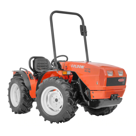
Textron Steiner 425 Owner's manual

Owner/Operator's Manual
Form # 09-223A
4 x 4 SUPER TRACTOR
Model 425
CAUTION
Avoid injuries. Read and understand Operator’s manual
before operating tractor or equipment.
It contains instructions for safe operation.

Date of Purchase: Month ________________Day____________________Year _______________
Dealer Name _________________________Phone__________________
Serial Number ________________________
Model Number ________________________
ALWAYS GIVE MODEL AND SERIAL NUMBER WHEN ORDERING SERVICE PARTS
• READ AND UNDERSTAND OPERATORS MANUAL
BEFORE OPERATING OR SERVICING.
• OBEY ALL SAFETY INSTRUCTIONS. FAILURE TO DO SO
MAY RESULT IN INJURY TO YOU OR OTHERS.
• BE SURE MACHINE IS IN SAFE OPERATING CONDITION
BEFORE USE.
• INSPECT MACHINE DAILY. REPLACE ALL WORN OR
DAMAGED PARTS.
• KEEP ALL GUARDS AND SHIELDS IN PLACE.
• CHECK OPERATION OF ALL SAFETY INTERLOCK
SWITCHES DAILY.
• DO NOT OVERRIDE INTERLOCK SYSTEM, IT IS FOR YOUR
PROTECTION.
• DO NOT ALLOW MINORS OR THE INEXPERIENCED TO
OPERATE MACHINE.
• KEEP PEOPLE AND PETS A SAFE DISTANCE AWAY FROM
MACHINE USING POWER DRIVEN ATTACHMENTS.
INJURY COULD RESULT FROM FLYING DEBRIS.
CAUTION
STEINER TURF EQUIPMENT, INC.
289 N. Kurzen Rd., P.O. Box 504
Dalton, Ohio 44618
Telephone: (330) 828-0200
FAX: (330) 828-1008

TABLE OF CONTENTS
INTRODUCTION SECTION 1 page
Introduction..........................................2
Specifications ........................................3
SAFETY SECTION 2
General Safety ........................................4
Operator Safety .......................................4
PRE-START INSTRUCTIONS SECTION 3
Starting Instructions .....................................5
Fuels and Oils ........................................5
OPERATION SECTION 4
Controls ...........................................6
Operating Precautions ....................................8
Operating Instructions ....................................10
Tractor Operation ......................................11
SERVICE SECTION 5
Service Schedule.......................................15
Oil Change Procedures ...................................17
Emergency Moving......................................18
Adjustments .........................................18
Trouble Shooting Chart ...................................20
ATTACHMENTS appendix
Roll Bar............................................A-1
Weights............................................B-1
3-Point Hitch .........................................C-1
Warranty ...........................................last page
1
Form #09-223A 10/91

INTRODUCTION section 1.1
Description
»The Steiner 4 wheel drive tractor is designed with the user in mind. From the rugged
industrial frame to the operator controls the tractor is ready for demanding turf and grounds
care assignments.
»Power steering and articulated frame, combined with a low center of gravity and high
flotation tires, provide exceptional maneuverability.
»Fully hydrostatic, single lever control lets you choose infinite ground travel speeds to
match the task. No clutching, jerking or braking, just smooth power flow to the 4 full time
drive wheels for added traction in tough areas. 2-speed transaxles allow a choice of
“HIGH” or “LOW” range.
»Front mounted attachments offer a wide range of working tools and all of them attach to
the “Quick Hitch” that is a Steiner exclusive. The front hitch is standardized for all models
of Steiner power units so your present attachments are not obsolete.
»You can do many tasks with this one tractor, compared to higher priced single purpose
machines, by simply changing attachments in less than 2 minutes.
» Operator safety and comfort, power, performance and dependability will provide years of
enjoyment with your Steiner tractor.
2

INTRODUCTION section 1.2
SPECIFICATIONS
Dimensions:
Overall Width _______________50"
Overall Length ______________74"
Overall Height ______________46"
Wheelbase________________44"
Inside Turning Radius ___________45"
Weight, Kubota D950B ___________1260 lbs.
Weight, Onan P224 ____________1150lbs.
Engine:
Standard ________________Onan P224 Performer
24 HP air-cooled
Optional _________________Kubota D950B Diesel
liquid-cooled 21.5 HP
Drive Train:
Transmission _______________Sundstrand Hydrostatic
Series 15 Pump and 2 motors
Transaxles ________________Peerless 2500
2-speed
Forward Speed (Kubota engine) _______0-9.1 MPH (high range)
0-4.7 MPH (low range)
Forward Speed (Onan engine) ________0-10 MPH (high range)
0-5.2 MPH (low range)
Reverse Speed ______________0-5.7 MPH (high range)
0-2.9 MPH (low range)
Steering _________________Hydraulic power steering
Parking Brake ______________Foot Activated, dry disc type
Tires:
TurfType ________________24x13.00-12 4 ply
Electrical:
Starting _________________12volt, Key switch
Battery _________________12volt, Group 22F
Fuel System:
Tank capacity_______________7Gallons
Fuel Pump ________________Diaphragm (Onan)
Electric (Kubota)
Specifications are subject to change without notice.
3

4
SIGNAL WORD DEFINITIONS
DANGER- Indicates an imminently hazardous situation which, if not avoided, will result in death
or serious injury. This signal word is limited to the most extreme cases.
WARNING- Indicates a potentially hazardous situation which, if not avoided, could result in
death or serious injury.
CAUTION- Indicates a potentially hazardous situation which, if not avoided, may result in minor
or moderate injury and/or property damage. It may also be used to alert against unsafe
practices.
ATTENTION: This symbol
identifies potential health
and safety hazards. It
marks safety precautions.
ATTENTION: Your safety
and the safety of others is
involved.
GENERAL SAFETY
1. Read and understand the owner’s manual,
before attempting to operate this machine.
2. Operate all controls from the operator’s seat.
NO RIDERS.
3. Keep all shields in place and safety switches
adjusted properly.
4. Do not leave equipment unattended. STOP
the engine and remove the key.
5. Do not allow minors or the inexperienced to
operate this machine.
6. Keep people and pets a safe distance away
from machine using power driven attachments. Injury
could result from flying debris.
SAFETY section 2.1
BE ALERT!
OPERATING SAFETY
. STOP ENGINE to install drive belts or make
adjustments.
2. WARNING! The tractor may coast when the
engine stops.
3. DO NOT TOW!...(See emergency moving
stalled unit instructions in Section 5.)
4.DONOTattempt towork onunit orany attach-
mentswith theenginerunning. STOPENGINE!
•
•5. Before leaving the tractor seat:
1. Disengage mower drive
2. Set Parking Brake
3. Stop engine

5
PRE-START INSTRUCTIONS section 3.1
BEFORE STARTING:
1. READ SAFETY DECALS
2. Check engine and transaxle oil levels.
3. Check coolant level.(Kubota)
4. Visually check tires.
5. Visually check for loose or missing parts or bolts.
6. Fill with clean fuel.
STARTING INSTRUCTIONS:
1. Safety switch requires PTO to be OFF for engine to
start.
2.Open throttleapproximately one-fourthofits travel.
3. Turn key counter-clockwise to “preheat” until indi-
cator light goes off. (diesel only). No preheat is re-
quired when engine is warm.
Pull choke on gasoline engine.
4. Turn key to start engine.
5. Warm up engine at medium speed. Push choke in on
gasoline engine as engine warms up.
6. In cold weather, allow the hydraulic oil to warm up a
few minutes at medium engine speed before using
tractor.
SPECIFICATIONS FOR FUELS AND OILS
ENGINE OIL (Kubota engines)
Fill the crankcase with oil that meets API service
designation CC or CD for diesel engines and SF for gas-
oline engines. Do not mix brands or grades of oil. Rec-
ommended weights for expected temperatures are:
Above 77 F.(25 C.)..........SAE 30
32 F.-77 F.(0 C.-25 C.).....SAE 20 or 10W-30
Below 77 F.(0 C.)..SAE 10W or 10W-30
ENGINE OIL (Onan)
Fill the crankcase with oil that meets API service
designation SE or SE/CC. Do not mix brands or grades
of oil. Recommended weights for expected tempera-
tures are:
Above 32 F.(0 C.)..........SAE 30
Below 32 F.(0 C.)..........SAE 5W-30
COOLANT (Kubota)
Fill coolant system with a mixture of 1 part Perma-
nent Anti-freeze and 1 part water.
FUEL
On gasoline engines, use clean, fresh, regular or un-
leaded fuel. Use of unleaded fuel results in less mainte-
nance.
On diesel engines, use clean, fresh, No. #2 diesel
fuel. In extreme cold temperatures No. #1 diesel fuel
may be used. Do not use kerosene or damage to en-
gine may result. Refer to engine manual for fuel bleed-
ing instructions.
TRANSAXLE HYDRAULIC OIL
Fill transaxle to the safe range with Steiner
Trans-Hydraulic Oil or Texas Refinery Corp. 6440 Uni-
versal Torque Fluid only. Do not use automatic trans-
mission fluid, motor oil, or any other type of hydraulic
oil.
NOTE: THE USE OF ANY OIL OTHER
THAN STEINER APPROVED OIL MAY VOID
WARRANTY AND IS NOT RECOMMENDED.
CAUTION! NEVER USE ETHER
AS A STARTING AID OR
SEVERE DAMAGE TO ENGINE
MAY OCCUR.
BE ALERT! STOP RUNNING
THE UNIT AT THE FIRST SIGN
OF ANY ABNORMAL HYDRAU-
LIC FUNCTION. SERIOUS DAM-
AGE TO THE HYDRAULIC SYS-
TEM CAN RESULT!
DANGER! NEVER FILL
FUEL TANK WITH ENGINE
RUNNING!

6

7

8
OPERATION section 4.3
OPERATING PRECAUTIONS
•Observe all Safety Decals.
•Keep all Shields in place.
•Do not allow minors or the inexperienced
to operate machine. NO RIDERS!
•Do not operate mower with other persons
in the area. Irregularities in ground
surface can permit foreign material to be
propelled from beneath deck to cause
serious injury or death.
•Beforeleavingoperator'sseat,disengage
PTO,moveFORWARD--REVERSE levertoNEUTRAL,setPARKINGBRAKEand STOP ENGINE.
•Remove key from ignition if maintenance procedures are to be performed or tractor is to be left
unattended.
•Counter balance weights are required for some attachments. See the Owner/Operator's Manual for
each attachment to determine proper counter weights.
•Tire pressures are very important! Check tire pressures according to Service Schedule (Section 5.1)
OPERATING ON SLOPES
USE EXTRA CARE WHEN WORKING ON SLOPES. The operator must be experienced with the
Steiner tractor and it's unique operational responses. A ROPS roll bar and seat belt is essential. Be alert to
dips and rises which change the general slope. Watch for holes, rocks, and roots in the terrain and other hid-
denhazards.Keepawayfromdropoffs.Avoidground conditions which willcausethemachinetoslide.Main-
tain engine RPM and control ground speed with the Forward -- Reverse lever.
The following recommendations for slopes are only a guide, based on normal turf conditions. If the
operator is uncomfortable or unsure of the machines stability, he should cease operation on the slope
immediately.
30 Degrees max. down slope in forward.
25 Degrees max. across slope.
30 Degrees max. up slope in forward.
25 Degrees max. backing up slope in reverse.
30 Degrees max. backing down slope in reverse.
On uneven, loose or wet ground, the angles should be reduced. Only smooth maneuvers (not erratic)
should be made to help maintain stability. Use LOW RANGE (1), avoid high speeds and sharp turns on
slopes. Do not start or stop suddenly when going uphill or downhill. THE ULTIMATE RESPONSIBILITY
FOR SAFE OPERATION ON SLOPES RESTS WITH THE OPERATOR.
USE LOW (1) RANGE
ON ROUGH, UNEVEN OR STEEP TERRAIN
AND
FOR OPERATION OF MOUNTED ATTACHMENTS
WARNING

9
Position Less than 10 minutes
continuous operation Continuous
operation
Front up 30° 25°
Front down 30° 25°
Left or right
side down 30° 25°
OPERATION section 4.4
MAXIMUM ENGINE INCLINATION RECOMMENDATIONS
When using an engine in an inclined position continuously, the following points must be
remembered:
•1. On water cooled engines there is a possibility of an air pocket forming in the cylinder head due to
inadequate circulation and/or coolant vaporization.
•2. The effective volume of the fuel tank becomes less, so air suction must be prevented.
CAUTION!
Continuous operation on slopes exceeding
25° is not recommended.

10
1. Read and understand this manual before
attempting to operate this machine
2. Check all fluid levels before starting unit.
3.Become familiar with allcontrolsand their
functions.
4. Safety switch requires the PTO lever in
the “OFF” position to start engine.
5. Select desired engine speed with the
throttle.
6. Vary vehicle speed with the Forward -
Reverse lever.
7. ALWAYS OPERATE WITH BOTH
TRANSAXLES IN THE SAME RANGE. BOTH IN
HIGH (2) OR BOTH IN LOW (1). Select “LOW” (1)
range with the transaxle shifters for operating front
mounted equipment.
8. Operate mower and other similar front
mounted equipment with the front lift lever in
“FLOAT” position.
9. Safety seat switch requires operator to be
seated when PTO is “ON” or engine will stop. On
units equipped with electric clutch, the seat switch
requirestheoperatortobeseatedwhenthePTOis
“ON” or the clutch will disengage and the PTO will
stop.
10. The hydrostatic transmission provides a
brakingaction when the Forward- Reverse lever is
returned to neutral.
11. Set parking brake and stop engine
before dismounting.
12 DO NOT TOW! ... Transaxle shifters
must be in “NEUTRAL” position before moving a
stalled unit. Neutral detent is between “HIGH” (2)
and “LOW” (1) position.
13. Be alert for loose bolts and nuts. It is the
operator’s responsibility to keep bolts tight.
14. See the following pages for more
information on specific operator controls and
adjustments.
CAUTION
BE ALERT! STOP RUNNING THE UNIT AT
THE FIRST SIGN OF ANY ABNORMAL
HYDRAULIC FUNCTION. SERIOUS DAMAGE
TOTHEHYDRAULIC SYSTEM CANRESULT!
DO NOT TOW! SERIOUS DAMAGE TO
HYDRAULIC SYSTEM WILL RESULT. ALWAYS
OPERATE WITH BOTH TRANSAXLES IN THE
SAME RANGE. BOTH IN “HIGH” (2) OR BOTH
IN “LOW” (1).
OPERATING TIPS
A. Take some time and get used to the handling characteristics of your new tractor.
B. Always look before backing.
C. Tractor must be equipped with ROPS roll bar when operated on slopes.
D. Slow down... Use “LOW RANGE” (1) over rough, uneven or steep terrain.
E. Do not make sharp turns at high speeds.
F. When going down hill with mower on, be sure mower is in “FLOAT” position.
G. When front mounted attachment cannot be lowered, BACK down the hill.
H. Do not expect your tractor to think for you! USE COMMON SENSE!
CAUTION
OPERATION section 4.5
OPERATING INSTRUCTIONS

11
Photo 4 - PTO Drive and Front Lift
OPERATION section 4.6
ATTACHING PTO BELT DRIVE (Serial No. 1001 -- 1641)
•The attachment drive belt is installed around the left hitch arm before the attachment is connected to
the front lift Quick Hitch. Attach the implement.
STOP ENGINE!
•Releasethebelttension adjustmentleverontheleftfront frame.Placethedrivebelton thepulleys.
Follow these steps to assure proper belt tension:
1. With the implement and drive belt attached, move the belt tension adjustment lever forward a notch at a
time and observe the double pulley as it moves toward the left and downward. The pulley must move
down approximately 3/4 inch. This assures the implement belt is tightened.
2. Start engine and engage the PTO lever carefully. The implement should start to run immediately. (ON
position)
3. Raise the implement to the highest position and check for proper release (implement stops running) when
the PTO is disengaged. (OFF position)
4. If the implement continues to run with the PTO in the “OFF” position, STOP ENGINE, release the belt
tension adjustment lever one notch and repeat steps 2, 3 & 4. If the PTO does not release, check for a
wrong size implement belt.
FRONT LIFT
•The front lift control valve is equipped with a detent float position. Always use “FLOAT” position when
mowing, sweeping, etc.
•The QUICK HITCH allows fast interchange of attachments. Push down on hitch control handle to open
latches. Pull up to close and lock latches.
AUXILIARY HYDRAULICS
•The auxiliary valve and quick couplers are standard equipment. Keep dust covers in place when
couplers are not in use. Be sure hose end couplers are clean before engaging couplers.
CAUTION!
Do Not Operate Implements With Improper
Belt Tension Settings.
Always Engage and Disengage PTO at Low Engine RPM.

12
OPERATION section 4.7
Operating Instructions for Electric PTO Clutch (Serial No. 1642 - )
follow these steps for implement drive belt installation:
1. Place the correct size implement drive belt
around the left hitch arm of the implement
beforeattachingto the quick hitch front lift. See
the belt size chart (section 4.7) for belt sizes.
2.Attach the implement tothe front lift. Pushdown
on the latch handle to open latches. Pull up to
lock latches.
3. Stop engine and release the belt tension
adjustment lever by moving it as far as it will go
toward the rear.
4. Install the implement drive belt on the double
idler pulley.
5. Each time a PTO belt driven attachment is
installed, it is necessary to adjust the drive belt
tension. This is done by moving the belt
tension adjustment lever on the left side of the
front tractor frame. (See Photo 4A) Proper
tension is very important! The proper setting is
obtained by moving the lever two notches after
all slack is taken up on the drive belts. If drive
belt slips, tighten one additional notch.
6. The PTO clutch is engaged or disengaged with the PTO push-pull switch. Engage the clutch with the
engine at approximately 1/2 throttle.
7. NOTE: The operator must be seated for the PTO electric clutch to operate. Do not attempt to by-pass this
safety device.
8. SPECIAL INSTRUCTION FOR DIESEL ENGINES: To stop the engine... Pull the knob on the fuel shut-off
cable and hold it until the engine stops. Push it in after the engine stops so the engine is ready to start the
next time. Engine will not start with the fuel shut-off knob pulled out.
Photo 4A - Belt Tension Adjustment Lever
CAUTION!
DO NOT ENGAGE CLUTCH WITH ENGINE AT FULL THROTTLE.
STARTING HEAVY LOADS AT FULL THROTTLE WILL SHORTEN
CLUTCH AND/OR BELT LIFE.

13
OPERATION section 4.8
Belt Size Chart for Steiner Tractors and Attachments
Model Description 425
without electric clutch
*Part No.
425
with electric clutch
*Part No.
Engine Drive Pulley to Idler 81-B042 81-B041
BM425 Boom Mower 81-B041 or 81-A040 81-B040
All Rotary Mowers 81-B041 or 81-A040 81-B040
PB100 Power Blower 81-B041 or 81-A040 81-B040
RM674 Reel Mower 81-B044 or 81-A043 81-B043
RS350 Rotary Sweeper 81-B041 or 81-A040 81-B040
SB348 Snowblower 81-B054 or 81-A053 81-B053
SC101 Stump Cutter 81-B045 or 81-A044 81-B044
TL348 Tiller 81-B041 or 81-A040 81-B040
* See attachment Parts Manual for correct belt part numbers.
Use only Steiner approved belts.
Photo 4B - Electric Clutch Access Door
TIRE BALLAST
Liquid, foam, rubber or powder ballast in
tires causes excess loads on the drive train and
WILL VOID WARRANTY ON THE DRIVE TRAIN
COMPONENTS of the power unit. Modified or
makeshift weights are not acceptable.
Rear weights must be used with attachments
over 120 pounds for stability. See attachment
operator's manual for weight requirements.
Always remove all rear weights when front
mounted attachments are removed, or when
using attachments less than 120 pounds, to
reduce the danger of unit tipping over backward
while climbing steep slopes or loading ramps.

14
OPERATION section 4.9
Hydraulic System Warning Horn
SOUNDING HORN INDICATES LOW HYDRAULIC
OIL PRESSURE. SEE DECAL UNDER TOOL BOX
COVER AND OPERATOR’S MANUAL FOR
INSTRUCTIONS.
CAUTION!
This unit is equipped with a warning horn to signal low hydraulic oil pressure.
A hydraulic oil pressure switch monitors the charge pressure of the hydrostatic system, and gives a
warningsignalifthe charge pressuredropstoanunsafe level. Continuedoperationwithlowchargepressure
will result in severe damage to the hydraulic pump and motors.
IF HORN SOUNDS, CHECK THE FOLLOWING:
1. Is unit operating under heavy load in “HIGH”(2) range?
Shift both transaxles to “LOW”(1) range and proceed.
2. Low hydraulic oil level or wrong type of oil.
Check oil level and fill with approved hydraulic oil.
3. Dirty or plugged hydraulic filter.
Replace with an approved filter.
4. Check for air leaks in filter base, suction lines or fittings.
Repair or replace damaged parts.
5. If horn signal continues after checking steps 1 to 4, there may be internal damage to the
hydrostatic pump and motors.
Contact dealer for service.

15
SERVICE section 5.1
SERVICE SCHEDULE
DAILY
PRESTART 50
HOUR 100
HOUR 500 HR
ANNUAL
SERVICE INTERVAL
SERVICE INSTRUCTIONS
Read safety decals. X
Check fuel level. X
Check engine oil level. X
Check transaxle oil level. X
Check air cleaner. X
Visual inspection of:
1. Bolts and fittings for signs of loosening. X
2. Accumulation of dirt or foreign matter around
engine restricting engine cooling. X
3. Oil leaks or belts and hoses showing signs
of wear. X
4. Tires for low pressure or signs of abnormal
wear. X
Change engine oil and filter:
1. ONAN engines:
initial change at 25 hours
and 50 hours thereafter. X
2. KUBOTA engines:
initial change at 35 hours
and 100 hours thereafter. X
Check air cleaner:
Clean or replace. XXXX
Check battery water level:
Fill to cover plates 1/4". XXX
Transaxles:
Check transaxle oil level. XXXX
Refill with Steiner Trans-Hydraulic Fluid or
TRC 6440 Universal Torque Fluid. Do not use
automatic transmission fluid or motor oil.
Initial hydraulic oil change 100 hours. X
Initial filter change 50 hours. X
Change hydraulic oil every 500 hours. X
Replace hydraulic oil filter every 500 hours or
at the first sign of any abnormal hydraulic function. X
BE ALERT!
Stop running the unit at the first
sign of any abnormal hydraulic
function. Serious damage to the
hydraulic system can result.

16
SERVICE section 5.2
SERVICE SCHEDULE
DAILY
PRESTART 50
HOUR 100
HOUR 500 HR
ANNUAL
SERVICE INTERVAL
Fuel system:
Check or replace fuel filter. X
Lubrication:
Grease center pivot. X
Check tire pressure:
Front - 16 lbs. max. X
Rear - 16 lbs. max. X
Storage:
Drain fuel tank. X
Maintain proper tire pressures. X
Remove battery and maintain charge. X
Grease exposed cylinder shafts. X

SERVICE section 5.3
ENGINE OIL CHANGE PROCEDURE
Onan:
25 hours initial;
50 hours thereafter.
Kubota:
35 hours initial;
100 hours thereafter.
1. Run engine until engine is warm for complete
draining.
2. Remove oil drain plug (Onan).
Open drain cock (Kubota).
3. Remove oil filter and wipe filter base clean.
4. Lube filter gasket with oil and install new filter.
Tighten 1/2 turn after seal contacts base. Do
not over tighten.
5. Re-install drain plug (Onan).
Close drain cock (Kubota).
6. Add 3 U.S. Quarts (2.9 liter) engine oil for Onan
engines. Add 4 U.S. Quarts (3.8 liter) for
Kubota engines. Refer to engine manual for oil
specifications.
7. Run engine and check filter and drain plug or
cock for leaks.
8. Stop engine and refill to proper oil level.
THE USE OF ANY AIR FILTER OR OIL FILTER
OTHER THAN THOSE SPECIFIED BY THE
ENGINE MANUFACTURER MAY VOID
WARRANTY AND IS NOT RECOMMENDED.
TRANSAXLE OIL CHANGE
PROCEDURE
Change hydraulic filter after first 50 hours.
Change hydraulic oil and filter at 100 hours
initially, and annually or at 500 hour intervals
thereafter, whichever occurs first. Change oil and
filter at any time contamination is suspected.
1. It is best to drain transaxles after the tractor has
been thoroughly warm to assure maximum
drain.
2. Remove dipstick and drain plugs from
transaxles.
3. Remove hydraulic filter and wipe filter base
clean.
4. Lube filter gasket with oil and install new filter.
Tighten 3/4 turn after gasket contacts filter
base. Do not over tighten.
5. Re-install drain plugs in transaxles.
6. Add 5 quarts (4.6 liters) to the rear transaxle. Fill
front transaxle to full mark on dipstick with
approved hydraulic oil. Use only Steiner
Trans-Hydraulic Oil or Texas Refinery Corp
6440 Universal Torque Fluid.
7. Run engine, and turn steering wheel extreme
right to extreme left several times to purge all
air from the circuit.
8. Shift both transaxles to neutral (neutral detent is
halfway between LOW and HIGH) and move
the Forward -Reverse lever back and forth to
purge air from the drive circuit.
9. Re-check oil level to be sure it is in the safe
operating range.
THE USE OF ANY OIL OTHER THAN STEINER
TRANS-HYDRAULIC OIL OR TRC 6440
UNIVERSAL TORQUE FLUID MAY VOID
WARRANTY AND IS NOT RECOMMENDED.
THE USE OF ANY HYDRAULIC OIL FILTER
OTHER THAN A STEINER HYDRAULIC OIL
FILTER MAY VOID WARRANTY AND IS NOT
RECOMMENDED.
17
TRANSAXLE OIL LEVELS
After a period of time the level on the front
transaxle dipstick may show to be low even
though there are no apparent oil leaks. This
condition could be caused by a transfer of oil from
the front transaxle to the non-vented rear
transaxle replacing the air cavity in the rear
transaxle.
Before refilling front transaxle to the top mark on
the dipstick,remove the “top plug” on the rear
transaxle and allow air to enter to equalize the oil
levels in the transaxles. After oil level is stabilized,
replace the plug and refill the front transaxle as
needed.
Equalize oil levels any time an excessive amount
of oil, more than a quart (liter), needs to be added
to the front transaxle.

EMERGENCY MOVING A STALLED UNIT
DO NOT TOW!
Transaxle shifters must be in neutral before
moving a stalled unit. Neutral detent is
between “HIGH ” and “LOW” position.
SERVICE section 5.4
ADJUSTMENTS
Throttle Adjustment
Tension adjustment is made by simply tight-
ening the spring loaded friction washers on the
throttle lever. High and low idle speeds are ob-
tained by adjusting the linkage at the engine.
HYDROSTATIC TRANSMISSION
Forward - Reverse Lever Tension
Adjustment
A large knob is located near the Forward -
Reverse lever. Turn clockwise to tighten tension
and counter clockwise to reduce tension. Addi-
tional tension may be needed whenever the lever
does not stay in the desired position.
Neutral Linkage Adjustment:
Absolute neutral is when the tractor will not
creep on a level smooth surface with the engine
running and the Forward - Reverse lever in neutral
position. If the unit creeps it is necessary to adjust
thecontrollinkage.Adjustthelinkage by loosening
the locking nuts at both ends of the rod and rotate
the rod to shorten or lengthen the desired amount.
Shorten the rod if the unit creeps forward or
lengthen the rod if the unit creeps backward.
Tighten locking nuts when neutral setting is cor-
rect. (see Photo 5)
18
Photo 5 - Hydrostatic Adjustments
CAUTION! DO NOT TOW!
SERIOUS DAMAGE TO HY-
DRAULIC SYSTEM WILL RE-
SULT.
Table of contents
Other Textron Tractor manuals
Textron
Textron Ransomes CT435 Specifications

Textron
Textron Ransomes Jacobsen HR3806 Series Guide

Textron
Textron Jacobsen Turfcat 600 Series Operating instructions
Textron
Textron RANSOMES LN Series Guide
Textron
Textron RANSOMES VN Series Guide
Textron
Textron Ransomes CT445 Specifications

Textron
Textron Steiner 420 Owner's manual

Textron
Textron Steiner 430 MAX Owner's manual
