TEXYS texense WTS User manual
WTS User Guide V05 Page - 1 -
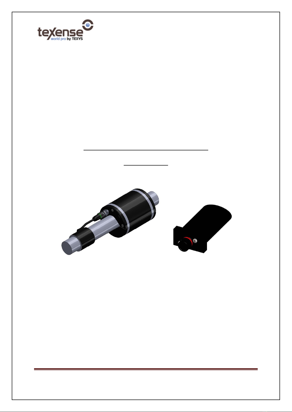
WTS (Wireless Torque Sensor)
User Guide

WTS User Guide V05 Page - 2 -
1. System contents
WTS wireless system includes the following components:
- 1 x Master box GenWM.
- Up to 22 slave torque sensors.
2. Installation recommendation
In order to reach the best performances for radiofrequency communication, we do recommend taking into
account the following recommendations:
- Both master box and slave sensors should be attached in a place where there is as less as possible
shield between antennas and air.
- Both master box and slave sensors should not be attached above a metal plate.
- If possible, it is recommended to not have any metallic parts closer than 20cm from both master
box and slave sensors.
3. Running the system
- Master box has to be connected and powered (see also specification sheet for pinout and operating
voltage).
- When switching ON the master box, CAN data should be received (see also CAN communication
chapter).
- The slave has a power management algorithm that includes radiofrequency and accelerometer
information (please refer to power management chapter for further details).
- When one or more slave sensors are switched ON from a sleep mode, RF connection should occur in
less than 1 minute and the system should run providing data on CAN bus.
- In addition, each slave sensor uses a 3-axis accelerometer for detecting the car state (steady or
moving).
WTS User Guide V05 Page - 3 -
4. Power management
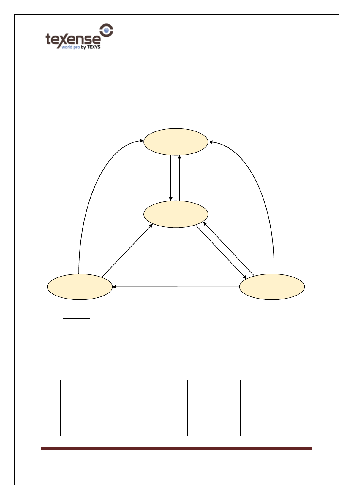
4.1 State machine
- Slave sensors are provided with a 1600 mAh primary battery.
- Batteries should be replaced when voltage drops below 3.15V.
(1) Master lost: No master was found for more than 40 seconds
(2) Car is moving: At least one accelerometer axis is higher than 2G (default value).
(3) Car is steady: Timeout elapsed with accelerometer’s 3 axis slopes lower than 1.5G (default value).
(4) Disconnect/Reconnect connector: The Deutsch connector between the gauge and the electronic module also
acts as a “switch” to power ON/OFF the system.
Current consumptions and LED pattern:
State
LED pattern
Consumption
SLEEP mode
OFF
<10µA
IDLE mode
OFF
100µA
RUN mode (emission 10Hz):
Fast blinking
10 mA
RUN mode (emission 50Hz):
Fast blinking
15 mA
RUN mode (emission 100Hz):
Fast blinking
20 mA
RUN mode (emission 200Hz):
Fast blinking
32 mA
RUN mode (waiting for RF connection):
Slow blinking
30 mA
RUN H mode
RUN L mode
IDLE mode
Car is moving (4)
Car is steady (3) for 4 minutes
OR Master lost (1)
Car is steady (3)
for 40 seconds
Car is moving (2)
SLEEP mode
Disconnect
connector (4)
Connect
connector (4)
Disconnect
connector (4)
Disconnect
connector (4)

WTS User Guide V05 Page - 4 -
RUN H mode definition:
The Run high mode is a run mode where the data acquisition is triggered with master selected data rate
(10Hz to 200Hz). Typically, this mode is intended to work when the car is running.
RUN L mode definition:
The Run low mode is a run mode where the data acquisition is sent at 10Hz. In this mode, the system still
provides data but with a smaller data rate to reduce battery consumption. Typically, this mode is intended
to work when the car is in the garage for test.
IDLE mode definition:
This mode is intended to have a small consumption when the system is not moved (typically in the
garage).
SLEEP mode definition:
This mode is intended to have a very small consumption when the system is not used for long term and is
susceptible to be moved (typically during the transport and storage).

WTS User Guide V05 Page - 5 -
5. RF Communication.
5.1 Overview.
5.1.1 RF Frequency
The system is configurable for being used in 868MHz, 902MHz or 920MHz frequency bands. As a
general guideline, 868MHz is dedicated to Europe when 902 and 920MHz are dedicated to
Americas and Asia-Pacific. Both master box and slave sensor uses RF transceivers that are suited
for systems targeting compliance with EN 300 220 (Europe) and FCC CFR Part 15 (US).
Nevertheless, approval for the finished product is not yet performed. Therefore, prior to use the
system in any country, we do recommend checking for local regulation.
RF Frequency can be set by end user on master side (please refer to master specification sheet).
Whatever the RF frequency is, any slave will be able to synchronize by scanning automatically all
bands without any configuration change.
5.1.2 RF pairing
When delivering a system, we provide a master box paired with up to 22 slave sensors. The
pairing mechanism is based on 3 parameters:
•Customer ID: this ID is factory set and cannot be changed by the end user. This prevents
from any interference between end users.
•System ID: this is the ID of a whole system including one master and up to 22 slaves. The
system ID must be the same for the master and all its slaves. So special care must be
taken regarding this parameter. In fact, using a same system ID for 2 different systems
will result in interferences between the 2 systems. The end user can use simultaneously
up to 16 different systems.
•Slave ID: This ID is dedicated to discriminate and identify the slaves. The end user can
use simultaneously up to 22 slaves. Depending on CAN data frequency used, this number
can be reduced (please refer to configuration section).
5.1.3 RF anti-collision mechanism
In order to deal with several systems in the same area, the system uses a channel jump
mechanism. There are 5 channels shared with 3 different channel jump sequences.
The channel jump sequence can be configured by the end user (please refer to configuration
section). In order for a team to get several cars communicating easily in the same box, we
recommend:
- to have a different channel jump sequence for each car.
- to have the same channel jump sequence for a whole system (a master and its paired
slaves would have the same channel jump sequence).
Note: About channel jump sequence, we can advise customer regarding the best option to choose
when ordering the system, depending on its application.

WTS User Guide V05 Page - 6 -
6. CAN communication
- CAN bus can run according to Bosch’s CAN 2.0A or 2.0B specification. The CAN type A or B is
configurable (please refer to GenWM datasheet).
- Data is available on the CAN bus according to 2 mechanisms:
•Standard mechanism: each data is classically defined by the CAN frame ID.
•Multiplexed mechanism. In this case, one single CAN frame ID is used for up to 22 slaves.
The frame itself contains other IDs to discriminate the data and the slave.
The mechanism is configurable, please refer to GenWM datasheet for more information.
- Data received by RF from any slave sensor, is converted to CAN frames and provided to ECU by
master box. The frames contain temperature measurements, battery voltage, sensors internal
temperature and a free running counter (please refer to master specification sheet for CAN IDs
and data formatting).
- If there is no slave sensor running around, master box will only provide the CAN frame dedicated
to free running counter.
- Even if the system is sized for up to 22 slave sensors, CAN frames dedicated to measurement are
sent only if data are received by RF. So the bus will be loaded only with consistent data.

WTS User Guide V05 Page - 7 -
7. Data rate
The end user can select between 2 data rate modes: the mono-frequency and the multi-frequency modes.
This feature can be changed on master side (please refer to master specification sheet). The term
“frequency” here defines the measurement refresh rate as it will appear on the CAN bus.
The master GenWM is a generic master and can work with multiple slave sensors. Moreover, it is possible
to mix the slave types (pressure sensors, temperature sensors, torque sensors…). As all slave types don’t
work at the same frequency, it is important to understand the behaviour of the whole RF system.
7.1.1 Mono-frequency mode
In this mode, all the slave measurements are triggered with the configured frequency but the number of
possible slaves to use is limited and depends on the chosen frequency:
•If configured to 200Hz, only 1 slave can be used (slave ID 1).
•If configured to 100Hz, only 3 slaves can be used (slave IDs 1 to 3).
•If configured to 50Hz, only 6 slaves can be used (slave IDs 1 to 6).
•If configured to 10Hz, all the 22 slaves can be used (slave IDs 1 to 22).
•If configured to 1Hz, all the 22 slaves can be used (slave IDs 1 to 22).
7.1.2 Multi-frequency mode
In this mode, all the slave measurements are not triggered with the configured base frequency. The system
will work as follow:
•If configured to 100Hz :
o2 slaves will work at 100Hz (IDs 1 and 2).
o10 slaves will work at 10Hz (IDs 3 to 12).
•If configured to 50Hz :
o4 slaves will work at 50Hz (IDs 1 to 4).
o10 slaves will work at 10Hz (IDs 5 to 14).
WTS User Guide V05 Page - 8 -
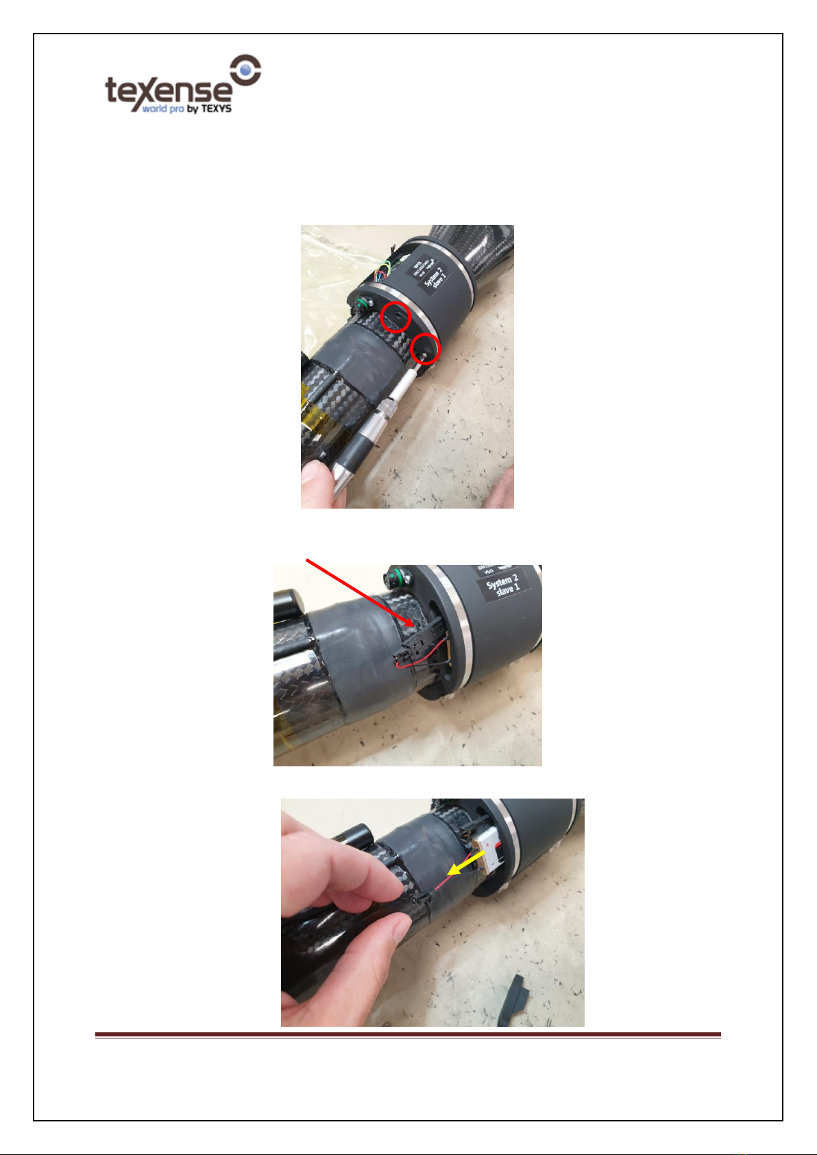
8. Replacing batteries on sensors.
1. Remove the 2 screws, the cover and the seal:
2. Disconnect the connector:
3. Remove the battery:

WTS User Guide V05 Page - 9 -
4. Put back the new battery
5. Put back the seal and the cover. Take care to place the wires in the dedicated slot of the cover to
avoid to pinch them
6. Put back the 2 screws. The recommended torque is 1N.m.
Slot

WTS User Guide V05 Page - 10 -
9. Changing parameters.
Many parameters can be configured by the end user. A CAN protocol is available for the end user to modify
the parameters: the “Texense’s CAN protocol”. Texense can provide this protocol on request.
9.1 Master GenWM configuration
The master parameters are basically:
- System ID
- CAN type
- data frequency
- RF band
- ...
Please refer to GenWM datasheet to see all available master parameters.
To modify a parameter, simply use the Texense’s CAN protocol.
9.2 Slave WTS configuration
The slave parameters are basically:
- Slave ID
- System ID
- idle acceleration thresholds
- …
Please refer to WTS datasheet to see all available slave parameters.
To modify a parameter, you must first establish a “configuration” RF connection between the slave and the
master then you can use the Texense’s CAN protocol. To do this:
oStep 1: Power on only one master.
oStep 2: Execute the first 2 commands of Texense’s CAN protocol:
o“ID request” command (0x10). At this step, the master will stop to send CAN
data.
o“Setup mode” command (0x20).
oStep 3: Power on or wake up the slave to configure. It doesn’t matter whether the slave
was previously paired with the master, the RF connection will be forced. Do not power on
any other slave on the field. The led will blink fast indicating that the RF communication
is OK. At this step, you have direct access to the slave through the CAN.
oStep 4: simply use the basic commands of Texense’s CAN protocol to configure the slave
parameters.
Table of contents


