TH3D EZABL Pro User manual
If you were sent here from Creality, EBay, Aliexpress, Amazon or any other site
selling ABL kits be aware these are clones. They are NOT supported.
Buying them will directly impact our ability to continue to provide for the 3D
printing community and put food on our table.
Please click here to get a Genuine EZABL™kit from our website.
Before we start, we just wanted to thank you for choosing the TH3D EZABL™Pro kit.
We’ve been working on perfecting the easiest, well documented, and supported ABL kit
on the market. The EZABL™ Pro kit is the result of over 2 years of research and testing
done by TH3D and feedback given to us from our customers.
We pride ourselves by using the highest quality parts in the kits and doing extremely
thorough testing on every kit before packaging. Unlike other companies that use off the
shelf hardware and/or low-quality parts on their boards we only use the best and work
directly with our suppliers to bring you the best performing and reliable kits that we can.
We would not be where we are without YOU and your feedback. If you see something
that needs changing/updating or you just want to suggest a new feature, we would love
to hear from you. We can be easily reached by visiting ContactUs.TH3DStudio.com.
If something is not up to our rigorous QC standards, please let us know so we can
correct it.
TH3D gives back to the community through many ways and you supporting us allows us
to put out information for everyone as well as making donations every month to
multiple open source projects (like the Marlin project that our firmware is built on and
OctoPrint).
Thank you again for choosing TH3D and Happy Printing!
Sincerely,
~Tim Hoogland
V2.1 –1/12/2021 Need help? Visit ContactUs.TH3DStudio.com
TH3D EZABL™Pro Installation Guide -Copyright © 2021 TH3D Studio LLC –ALL RIGHTS RESERVED
2
TH3D EZABL™Pro
Installation Guide
V2.1 –1/12/2021
This guide is property of TH3D Studio LLC
Re-distribution is NOT permitted and must be downloaded from our website
ONLY FOR USE WITH EZABL™PRO KITS
Copyright © 2019 TH3D Studio LLC –ALL RIGHTS RESERVED

V2.1 –1/12/2021 Need help? Visit ContactUs.TH3DStudio.com
TH3D EZABL™Pro Installation Guide -Copyright © 2021 TH3D Studio LLC –ALL RIGHTS RESERVED
3
Getting Started
Welcome to the EZABL™Pro kit installation guide!
This will walk through the steps to install the EZABL™Pro sensor on the printer. Be sure to
follow all the steps and if you have issues or a question do not hesitate to reach out to us by
visiting http://ContactUs.TH3DStudio.com.
There are optional accessories for the EZABL™Pro Kit like AC power adapter or USB power
adapter that are not pictured below. If you ordered these options, they will be in the EZABL™
Pro kit package when you receive it.
We are always making things better so the case or sensor may look slightly different than the
below pictures.
V2.1 –1/12/2021 Need help? Visit ContactUs.TH3DStudio.com
TH3D EZABL™Pro Installation Guide -Copyright © 2021 TH3D Studio LLC –ALL RIGHTS RESERVED
4
Preparation
If you are not comfortable flashing your printer’s firmware, moving wires around, and/or taking your hotend
mount apart you should NOT be attempting this upgrade as you could damage the printer. Contact us with any
questions before hand if you are unsure of upgrading. Support covers the product itself. If you need assistance
with your slicer, tuning your machine, or other non-product related issues please check out our communities at
Community.TH3DStudio.com.
Before you begin you should have the following:
•TH3D EZABL™Pro Kit
o1x EZABL™Pro Control Box
oPower Wire
o1X EZABL™Pro or EZABL™Pro Mini Sensor (depends on your selection)
▪EZABL™Pro Mini Sensors will have 2x Adapter Rings included
o10X Zip Ties for Securing the Sensor Wiring
o1X Micro Screwdriver for Adjusting the Sensor and Screw Terminals
•Printed Parts to Mount the Sensor to your printer
oWe include a multitude of mounts in our Unified Firmware package in the
“EZABL STL Files folder”. You can also use any custom ones if you know the
sensor offset values (this is noted in the firmware).
oWe offer printed parts if you do not want to print your own.
Prices are about $10-30 (depends on the mount) for an ABS printed mount. If
you want one please contact us with the STL files for a quote.
oSmall ones like the can be purchased on the EZABL Product page or separately
on our site in the Printed Parts section.
•Latest copy of the Unified or Marlin firmware for your printer
oWe have firmware for over 20 different machines on our website for customers
–Check your order email for download info or download from
Firmware.TH3DStudio.com.
oIf you have a custom printer see the notes on the firmware section for the Marlin
setup guide.
•USB Cable to connect your printer to your PC to update the firmware
oYour board MUST have the bootloader already flashed on it to perform this
update. Check our video guide page at Bootloader.TH3DStudio.com to flash the
bootloader.
If you are missing anything from the TH3D EZABL™Pro kit please visit ContactUs.TH3DStudio.com.
Email support is included in the kit for setup, install, and firmware questions. Phone/Remote
Support is available at an additional charge.

V2.1 –1/12/2021 Need help? Visit ContactUs.TH3DStudio.com
TH3D EZABL™Pro Installation Guide -Copyright © 2021 TH3D Studio LLC –ALL RIGHTS RESERVED
5
Pre-Installation Checks
Before installing the kit, there are a few things we recommend checking to make sure the
printer is in optimal condition before installing the EZABL™Pro kit.
1. Make sure your bed is level if you are using springs still, use Loctite or superglue to lock
the nuts in place on the screws to prevent shifting.
a. You can replace springs with aluminum spacers from a hardware store. We also
sell solid mount kits that integrate bed wiring strain relief and optional camera
mounts for select models on our website.
b. Check all the wheels and eccentric nuts if your machine uses these.
2. Run through the Z axis checks that are outlined in our knowledge base.
3. Make sure the power cord your printer uses has a grounding plug. If you are using an
adapter and/or extension cord make sure they are also grounded. If it is not grounded
there can be electrical interference that can cause the sensor to not work
a. If you are using a separate power adapter, make sure the power adapter/usb
power source is on the same power strip as the printer.
4. Depending on what mount you are using, printer model, etc you may need additional
screws. Most mounts use M3 screws so it would be recommended to pick up an M3
screw assortment from TH3D, Amazon, or your local hardware store.
5. Some printers require a bootloader to load the firmware. You will need an Arduino Uno
with some jumper wires. We sell a bootloader kit in the TH3D Shop that comes with the
Uno and ALL the cables needed.
a. Any of the models with the 1284p chips require a bootloader.
b. The Anets, CR-10, Ender 2, Ender 3, Ender 5, and Wanhao i3 all use the same
process for the bootloader.
c. There is a video guide and information for flashing your bootloader at
Bootloader.TH3DStudio.com and you will need an Arduino Uno to flash the
bootloader using our guide.
Troubleshooting Information
If you should have issues with your EZABL™kit first visit our knowledge base on our website.
This is where we document all known issues with the machines these kits are used on. If you
cannot find a solution to your issue you can visit ContactUs.TH3DStudio.com.

V2.1 –1/12/2021 Need help? Visit ContactUs.TH3DStudio.com
TH3D EZABL™Pro Installation Guide -Copyright © 2021 TH3D Studio LLC –ALL RIGHTS RESERVED
6
Mounting the sensor
Once you have the new mounts you will need to install them on your hotend and then mount
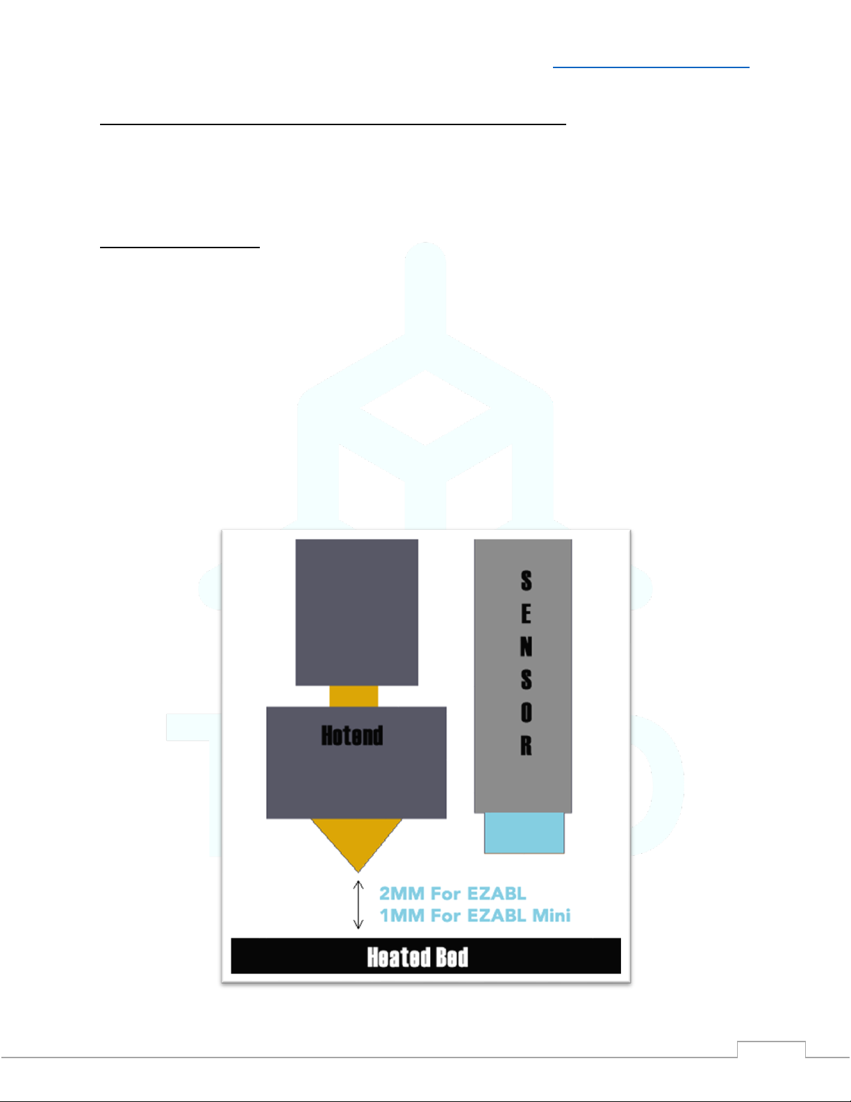
the sensor to the new printed mount. When you mount the sensor, it should be about 2mm
ABOVE the tip of the nozzle for both sensor sizes. This does not have to be exact just higher
than the nozzle but not too high. Most of the flat wrenches included with the printers are about
2mm in height and can be used to set the sensor height.
If you are using the EZABL™Mini size sensor and using the standard 18mm sensor mount use
the included adapter rings to center the EZABL™Mini in the 18mm mounting hole. The smaller
side should be inside the ring of the 18mm hole to center the probe.
Once mounted make sure the nuts are tight and you check them from time to time. If the nuts
loosen the sensor will not work reliably. You can use Loctite (blue preferred) to keep them in
place if this happens to your setup frequently.
2MM higher than nozzle.

V2.1 –1/12/2021 Need help? Visit ContactUs.TH3DStudio.com
TH3D EZABL™Pro Installation Guide -Copyright © 2021 TH3D Studio LLC –ALL RIGHTS RESERVED
7
Powering the EZABL™ Pro Control Board
Connect power to the EZABL™Pro Module is easy and flexible.
You can power the kit with the included power wire to your printer power supply OR if you
ordered the AC adapter/USB adapter you can power it externally.
Do not press the self test button with a sensor connected to the EZABL control board.
It is only for use when directed to be used by our support team. This emulates the sensor
trigger signal when pressed.
EZABL™ Pro Control Board Connections/Features
Separate Power Adapter
If you are using our AC adapter or USB adapter connect the DC plug to the DC Power Input Jack
on the EZABL™ Pro Control Board.
V2.1 –1/12/2021 Need help? Visit ContactUs.TH3DStudio.com
TH3D EZABL™Pro Installation Guide -Copyright © 2021 TH3D Studio LLC –ALL RIGHTS RESERVED
8
Directly Wiring Power
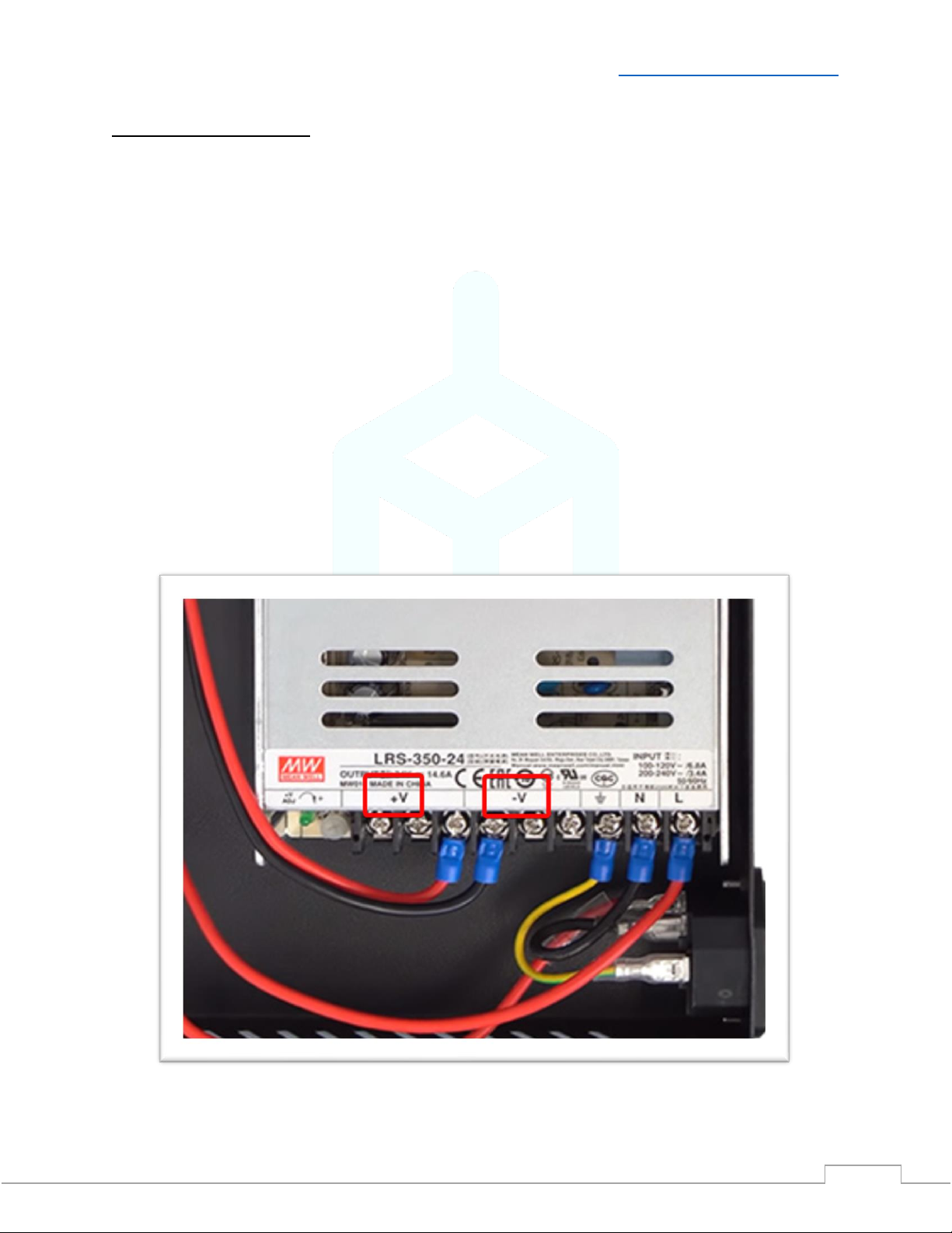
If you are wiring to your printer power supply, make sure that you match the positive and
negative connections on the power supply and EZABL™ Pro Control Board DC Power Input
Terminal. DO NOT connect to the AC lines.
The supplied wire has a red wire and a black wire contained inside the outer sheathing. Strip
this back at both ends and then strip the black and red wires at each end as well.
Positive is labeled with + on our board and usually is V+ on your power supply. Use the red wire
for this connection.
Negative is labeled with –on our board and usually is V- on your power supply. Use the black
wire for this connection.
Use the included screwdriver to secure the wires in the terminal, do NOT over tighten.
If in doubt sent a picture of the wiring to our support BEFORE you power the machine on and
we will verify proper connection
V2.1 –1/12/2021 Need help? Visit ContactUs.TH3DStudio.com
TH3D EZABL™Pro Installation Guide -Copyright © 2021 TH3D Studio LLC –ALL RIGHTS RESERVED
9
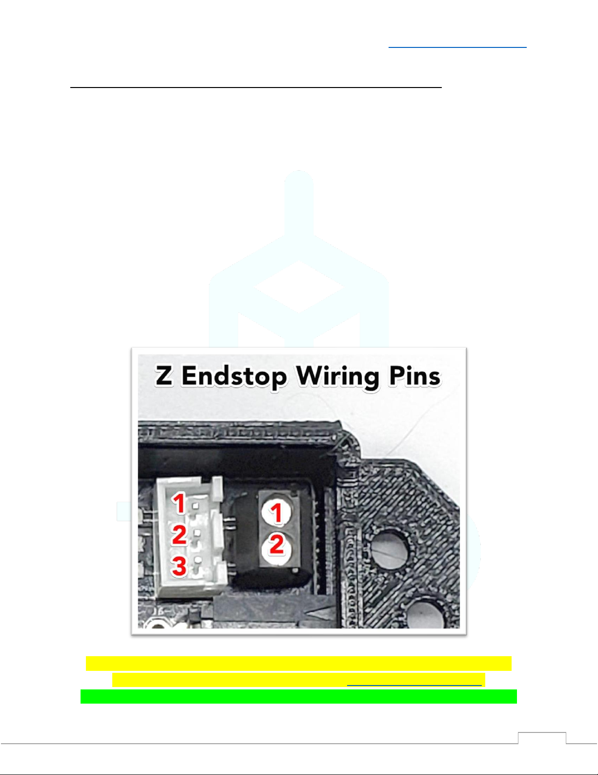
Connect your Z endstop to the EZABL™Pro Control Board
The EZABL™Pro Control board replaces your Z endstop switch. It accepts 2 types of Z endstop
connections, 2/3 Pin JST XH and stripped wires.
Printers with a 2 or 3 Pin JST XH Plug (Creality, Geeetech, Alfawise):
If you have a printer that uses a 2 or 3 pin JST XH plug then you can use the 3 pin header on the
EZABL™Pro Control Board.
If you have a 2 pin JST XH you will want to connect to pins 1 and 2.
Printers with soldered Z endstop wires:
If you have a printer with wires that are soldered to the Z endstop switch or one without a JST
plug, you will cut the wires and insert them into the black screw terminal on the right. Wire
placement does not matter. Use the included screwdriver to secure the wires in the terminal,
do NOT over tighten.
If you printer has 3 wires going to the Z endstop connection, please contact our support
BEFORE connecting. You can contact us through ContactUs.TH3DStudio.com.
For the Geeetech machines with a 3 pin endstop see our Knowledge Base for wiring the Z.
V2.1 –1/12/2021 Need help? Visit ContactUs.TH3DStudio.com
TH3D EZABL™Pro Installation Guide -Copyright © 2021 TH3D Studio LLC –ALL RIGHTS RESERVED
10
Verify Power and Test the EZABL™ Pro Sensor Detection
When you power on your printer the Power LED on the EZABL™Pro Control Board will light up
green. If the power LED is not lighting check that you have the polarity correct if directly wired
or if you are using a separate power adapter that it is plugged into a power source that is on.
Now plug the EZABL™Pro Sensor plug into the EZABL™Pro Sensor Connector on the control
board.
V2.1 –1/12/2021 Need help? Visit ContactUs.TH3DStudio.com
TH3D EZABL™Pro Installation Guide -Copyright © 2021 TH3D Studio LLC –ALL RIGHTS RESERVED
11
To verify that the sensor is working touch the tip sensor with your finger. The Red LED light on
the Sensor AND the Status LED on the EZABL™Pro Control Board should light up. Depending on
your sensor it may or may not also have a green power LED that will be lit (this will shut off
when triggered).
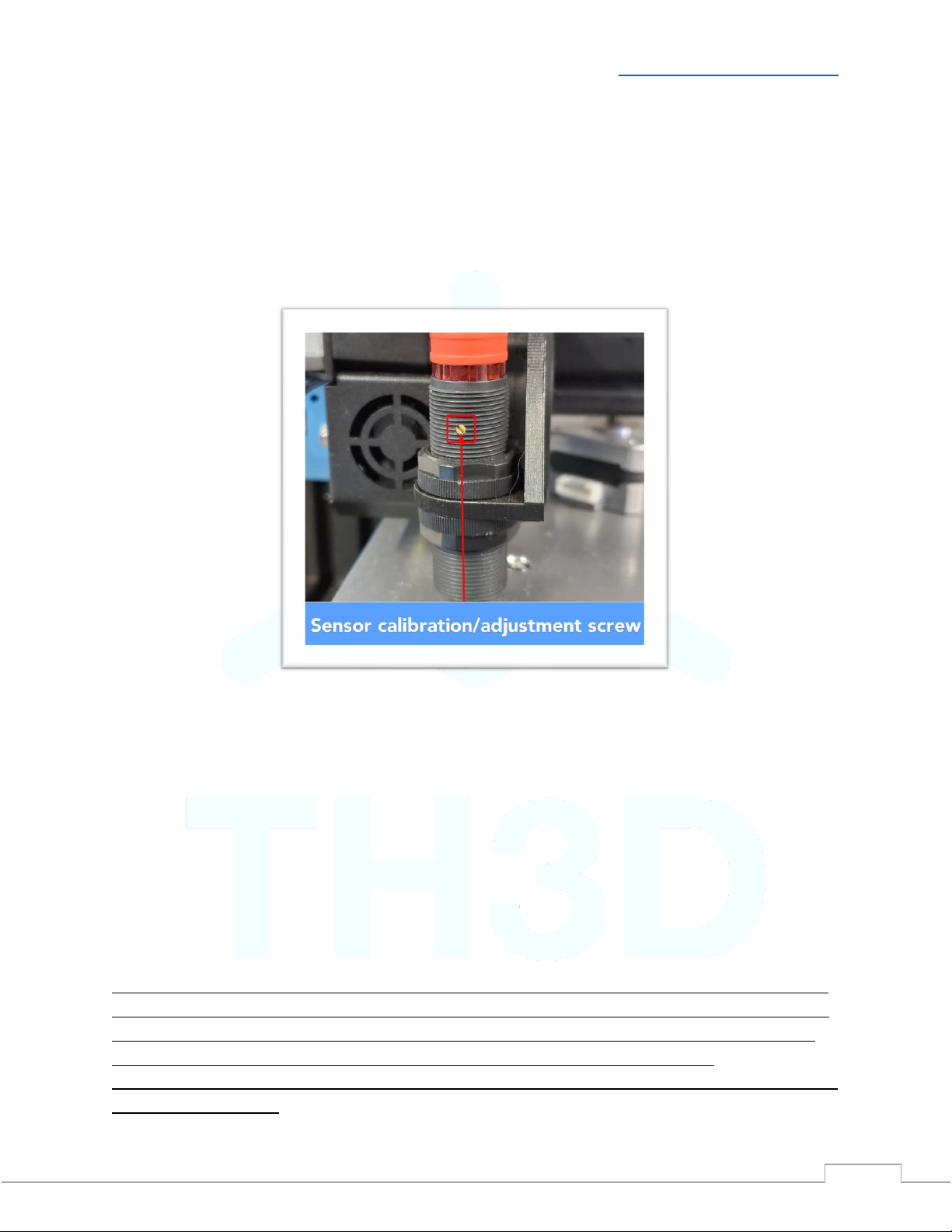
If they do not light up place your finger on the tip of the sensor while adjusting the gold screw
clockwise on the side of the sensor until it lights up when you touch it.
V2.1 –1/12/2021 Need help? Visit ContactUs.TH3DStudio.com
TH3D EZABL™Pro Installation Guide -Copyright © 2021 TH3D Studio LLC –ALL RIGHTS RESERVED
12
Firmware Setup –CLOSE ALL SLICERS BEFORE FLASHING
We support over 25 different printer models and all are listed on the Unified Firmware page.
•Download the latest Unified Firmware Package for your machine from
Firmware.TH3DStudio.com and extract all the files to a folder on your computer.
oCheck Unified 2 section for your machine/board support and if it is not
supported in Unified 2 yet then go with the Unified 1 firmware.
•Follow the directions at the top of the Configuration.h and on the firmware download
page for your machine.
oBe sure to follow each step and make sure you enable a probe mount for the
mount you are using on your machine.
•Set the EZABL_PROBE_EDGE setting to 45-50mm for larger printer beds (300mm+ size
beds) and 15-20mm for smaller printer beds.
oAdjust the probe edge so that it is not probing over any bed clips or screws. This
will skew the reading.
•We recommend using an EZABL_POINTS setting of 3 (this is the default) to start with
and most people use this value on beds up to 300x300. Larger beds should use 5.
If you have a printer that needs a bootloader this must be flashed before you can load any
firmware on the machine. Most printers with a 1284p CPU will need their bootloader flashed.
You can follow our bootloader flashing guide by visiting Bootloader.TH3DStudio.com
The EZABL™Probe mount STL files are included in the Unified Firmware package for every
model and probe mount variation that we support.
Be sure to reset your printer EEPROM by either going to Control>Reset EEPROM or you can
reset it via Gcode by sending a M502 followed by a M500. This will wipe the EEPROM and put
the firmware defaults in. Failure to do this step will result in erratic printer behavior.
Adding the EZABL™ Pro Kit to a Custom Printer
Setup the firmware as if you did not have a probe and follow our Marlin setup guide here:
https://support.th3dstudio.com/hc/en-us/articles/360043293552-EZABL-Firmware-Setup-for-Vanilla-Marlin
Custom Probe Mount Setup
If you have a probe mount you will need to measure the distance on X and Y that the center tip
of the probe is from the tip of the nozzle. Those will then be entered into the custom probe
section in the firmware. This is in the “Custom Probe Mount Settings” section and there is a
visual layout in the firmware showing an example.
V2.1 –1/12/2021 Need help? Visit ContactUs.TH3DStudio.com
TH3D EZABL™Pro Installation Guide -Copyright © 2021 TH3D Studio LLC –ALL RIGHTS RESERVED
13
Sensor/Endstop Test
The next step you want to do is to check if the endstop is properly being recognized by your
board.
Make sure you have your Z endstop wire connected to our EZABL™Pro Control Board.
DO NOT HOME YOUR Z OR “HOME ALL” UNTIL YOU VERIFY THAT THE FIRMWARE IS SEEING THE
SENSOR CORRECTLY AND YOU HAVE CALIBRATED THE SENSOR.
YOU CAN DAMAGE YOUR HOTEND AND/OR PRINTER.
Start by moving the Z up until the light on the sensor and the Status LED on the EZABL™Pro
Control Board turn off.
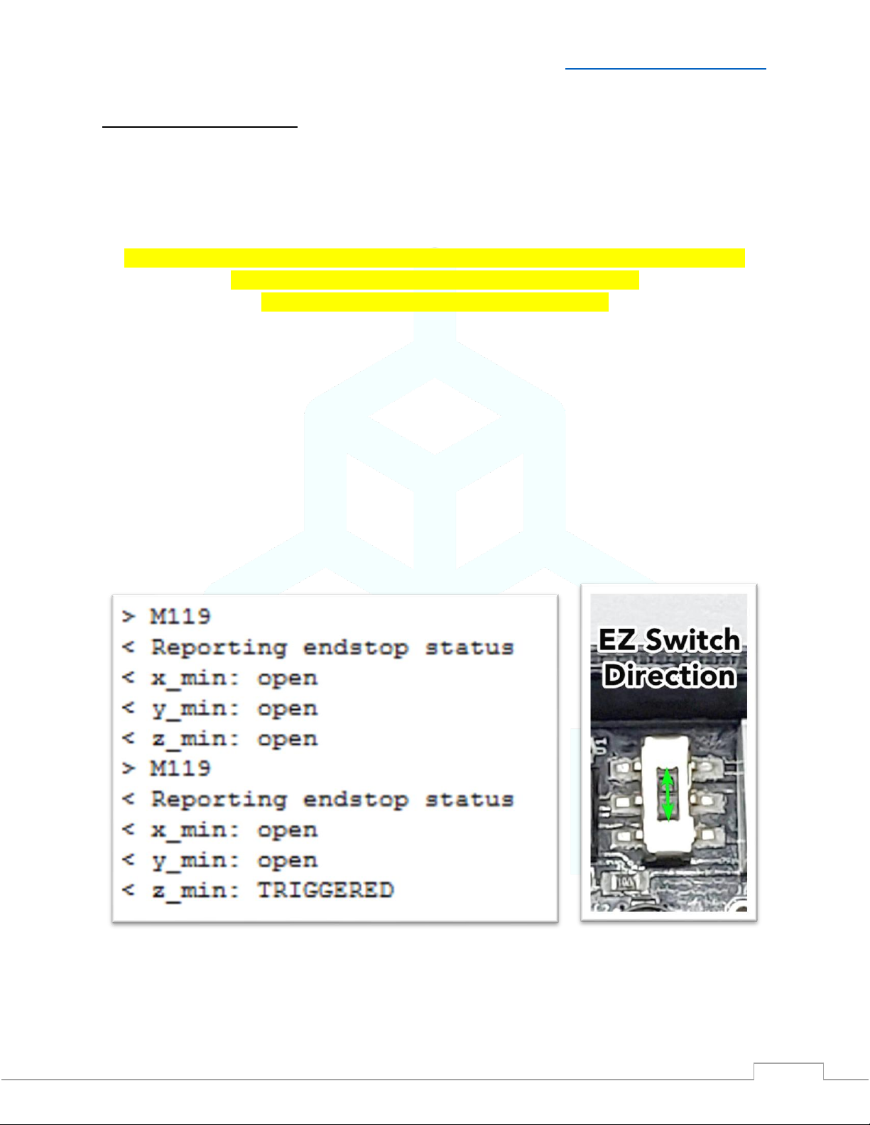
Next, connect to your printer over your preferred slicer (or Octoprint) and issue an M119 and
see if the Z_min is showing TRIGGERED or open.
If it shows open place your finger or an object under the sensor so the light comes ON and then
issue M119 again. If it shows TRIGGERED then proceed to setting your sensor sensitivity.
If your slicer (namely Cura) does NOT support sending terminal commands then use the Gcode
sender program in the “Extra Programs” folder of the Unified Firmware Package.
If it does not, then move the “EZ Switch” on the EZABL™ Pro Control Board and re-run the
M119 test. If it is in the up position, then move it down. If it is in the down position, then
move it up.
V2.1 –1/12/2021 Need help? Visit ContactUs.TH3DStudio.com
TH3D EZABL™Pro Installation Guide -Copyright © 2021 TH3D Studio LLC –ALL RIGHTS RESERVED
14
Mounting the EZABL™ Pro Sensor to your printer
Now that we have the wiring completed and verified that your printer is seeing the sensor
correctly it is time to mount the sensor on your machine. In the Unified Firmware package that
we downloaded earlier there is a folder called “EZABL STL Files”, all mounts are in here.
Install the sensor mount for your machine and place the sensor in the mount where it is higher
than the nozzle, we will adjust this in the next step. Use the sensor nuts to secure the sensor in
the hotend mount. Use the included zip ties to secure the sensor wire to your hotend wires.
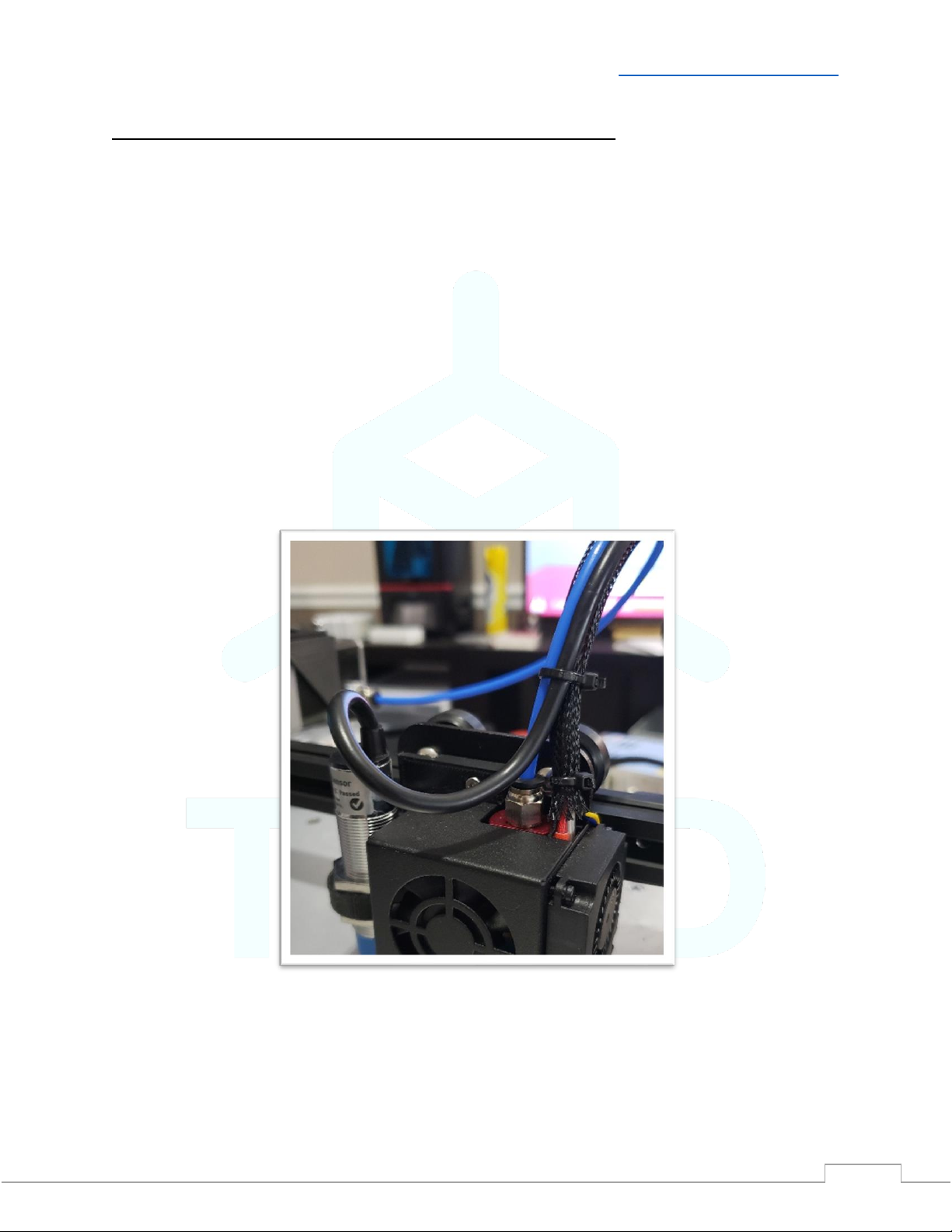
When you route the wire for your sensor so NOT create a pinch point with a zip tie where the
wire will be bending back and forth while the print head is moving. This will internally break the
wires on the cable and the sensor will no longer work. Leave some slack do NOT make a “loop”
with the wire. Install the sensor wire exactly as seen in the picture below, notice the curve of
the wire to the sensor top. This is what you want to see when you secure the wire. See
appendix for example of what NOT to do when installing the sensor wire.
Zip Tie/Wire Strain Notes
Do NOT overtighten the zip ties as you can damage your printer wiring and/or the EZABL™
Pro sensor wire. Damaged wires due to excessive zip tie force and/or improper strain relief
are not covered under warranty. See above picture for proper cable routing.
V2.1 –1/12/2021 Need help? Visit ContactUs.TH3DStudio.com
TH3D EZABL™Pro Installation Guide -Copyright © 2021 TH3D Studio LLC –ALL RIGHTS RESERVED
15
Calibrating the EZABL™ Pro Sensor for your printer
The next step is setting the sensor sensitivity. If you have a heated bed do this with your bed
heated to your normal print temperature. This is to account for the bed changing shape during
the heating cycle.
Status LED Information
•Both sensor sizes have a RED LED that lights when the sensor is triggered.
•18mm Size –Has 2 LEDs, a GREEN LED that lights to indicate power and shuts off when
the RED LED lights (triggered).
•12mm (Mini) Size - ONLY has the RED LED (triggered) and no green power led.
If you print at different temperatures depending on the material, you are printing then select
one in the middle of the highest and lowest print temps you use. Lower the Z until your NOZZLE
is on the bed, if you have filament on the nozzle heat it before lowering and clean it off.
Manually move the Z with the printer LCD or your Computer/Pi until the nozzle is on the bed,
then move the Z up 2mm for EZABL™Pro and 1mm for EZABL™Pro Mini.
V2.1 –1/12/2021 Need help? Visit ContactUs.TH3DStudio.com
TH3D EZABL™Pro Installation Guide -Copyright © 2021 TH3D Studio LLC –ALL RIGHTS RESERVED
16
If you have an AC bed turn the heat off during this step. If you have a direct drive printer
disable steppers as well to make sure E is off. This mitigates any potential EMI from the bed/e
motor.
The adjustment screw is on the SIDE of the sensor and gold/brass colored. Some mounts may
cover it up. If this is the case hold the sensor in position while calibrating it and then secure the
sensor with the included nuts after calibrating.
If the sensor RED LED is already on, turn the screw counter-clockwise until the RED LED turns
off. Now turn the screw clockwise slowly until the sensor RED LED turns on. Make sure the RED
LED stays on when you remove your screw driver AND move your hand away from the sensor. If
it shuts off or flickers when you do this turn it just a hair clockwise and move the screwdriver
and your hand out of the way again.
RED LED Turning off? - Repeat the clockwise adjustment until the RED LED stays on when you
remove your screwdriver and hand from the sensor. If you are having issues getting the RED
LED to stay on check the grounding on your machine, visit our Knowledge Base on grounding
checks and how to perform them.
Do NOT change the sensitivity if you are getting different heights between prints due to temperature
changes. This should be handled by the Z Offset/BabyStepping the Z height. Under normal conditions
at most you should only have to occasionally Babystep small amounts. If you are getting more than
that please contact our support to go through more advanced troubleshooting steps.
Large babystep changes are usually related to a physical machine issue if M48 is returning a consistent
reading under 0.01mm.

V2.1 –1/12/2021 Need help? Visit ContactUs.TH3DStudio.com
TH3D EZABL™Pro Installation Guide -Copyright © 2021 TH3D Studio LLC –ALL RIGHTS RESERVED
17
Setting your Z Offset
I HIGHLY recommend you watch the video as it is much easier to see what to do. Here is a video
on how to set the Z Offset: https://www.youtube.com/watch?v=IP-UHn7_yqs
Now that we have the sensor installed and calibrated you need to set your Z Offset. This is the
distance the printer needs to move the head down to place it on the bed after the sensor
triggers.
To set your Z Offset heat the bed to your normal print temp and do a G28 to home the sensor.
Your EZABL™Pro sensor should be in the middle of the bed. Let it sit there for 1 minute after
the bed has reached its target print temperature. After homing the Z will show 5mm. This is
NOT included in the ZOffset. Move Z down 5mm before proceeding.
What you will do now is grab a sheet of standard paper and then move the nozzle down by
0.1mm until it just grabs the paper. Once you do that you can look at your printer LCD and note
the number that the Z shows. This will be a negative number. That is what your Z Offset is.
Enter that number in the ZOffset section using your printer LCD, look for Probe Z offset. This is
located under Menu>Control>Motion. Make sure you store your Z Offset by going to
Menu>Control>Store Settings. If you do not store your memory the Z offset will be forgotten
when you restart the printer.
Now do another G28 command. The Z should show 5mm still but if you notice it will be 5mm as
the offset is considered when homing Z.
You can now move the nozzle down 5mm and it should be grabbing the paper. If it is too high
or too low you can further fine tune your Z Offset by increasing or decreasing that number. We
recommend using the babystepping Z feature below to fine-tune on your first print.
When printing if you are getting it starting too high or too low press the printer menu button
2 times while printing and it will bring up the “Probe Z Offset” menu. You can then turn the
knob left to bring the nozzle closer to the bed in real time or right to move it further away. It
is NORMAL to have to babystep a little especially when changing bed temps. If the resulting
1st layer is level after adjusting the 1st layer height then the probe is working correctly.
If you notice that you ALWAYS have to babystep a certain amount every print then add that
to the Z offset. Lets say you have to babystep -0.2mm and your offset is -2.0. You can change
your offset to -2.2mm and store it.

V2.1 –1/12/2021 Need help? Visit ContactUs.TH3DStudio.com
TH3D EZABL™Pro Installation Guide -Copyright © 2021 TH3D Studio LLC –ALL RIGHTS RESERVED
18
Updating your Slicer
Update your 1st Layer settings - To get the best 1st layer and adhesion we recommend the
following settings:
•150% 1st layer width
•0.3mm 1st layer height
•Print SLOW 25-30% speed or 20mm/s
•Use a skirt set 2-3mm from the part with 2-3 outlines. Use this to adjust/check the
leveling result.
oUse the Babystepping feature mentioned on the previous page to live adjust
your Z height.
•DO NOT TURN ON ANY SETTINGS IN YOUR SLICER TO MAKE THE HOME POSITION THE
CENTER OF THE BED. Your X0 Y0 position is still the same as it was before the upgrade,
which is the front-left corner of the bed.
Update your starting Gcode
•Open the “EZABL Starting Gcode V2.txt” file located in the Installation Guides folder.
•Copy the entire file contents and paste it into the starting code/scripts section of your
slicer replacing the existing code
The new gcode will have a 10 second wait for heaters to recover after probing. If 10 seconds is
not enough to let your heaters recover change the S10 in the starting code above to however
many seconds you want to wait for the heaters to recover.
Get into the habit of leaving your sensor homed BEFORE you start a print this will ensure that
the bed is in the same state as when the sensor was calibrated.
Your bed will warp/flex during each heating cycle and this minimizes getting an inaccurate
mesh when the sensor takes its readings.
You can now run your first print!
Slice up your favorite test file (ours is the 3D Benchy) and print!
Make sure to check the skirt and use the Babystepping feature to fine-tune your
first layer. If you made any adjustments be sure to store them using Control>Store
Settings.

V2.1 –1/12/2021 Need help? Visit ContactUs.TH3DStudio.com
TH3D EZABL™Pro Installation Guide -Copyright © 2021 TH3D Studio LLC –ALL RIGHTS RESERVED
19
Installation Finished!
Congratulations! You have installed your EZABL™ Pro sensor kit!
Enjoy the benefits of having Automatic Bed Leveling on your printer!
Things to note
•Make sure you are only using Gcode that was sliced after you installed the kit so that the
starting code is present. If it is not then the system will not work correctly
•Join our communities! Check them out at Community.TH3DStudio.com
•Make sure your machine is mechanically sound in terms of your belts, leadscrews,
wheels (if any), and hotend mount
oIf you have a Creality Ender 3/3X/Pro look up “The Edge of Tech” as they have
some great assembly/troubleshooting guides for the Ender 3
•Be sure to check the sensor nuts from time to time to make sure they are not “walking”
loose. If they are you can secure them with some Loctite Blue thread locker to make
sure they are staying put.
•Most issues that come up are machine related and not issues with the kits themselves.
Be sure to rule our machine issues and check our Knowledge Base before contacting
support.
•If you should have issues with your EZABL™kit first visit our knowledge base at
Support.TH3DStudio.com. This is where we document all know issues with the
machines these kits are used on. If you cannot find a solution to your issue you can
reach technical support at ContactUs.TH3DStudio.com

V2.1 –1/12/2021 Need help? Visit ContactUs.TH3DStudio.com
TH3D EZABL™Pro Installation Guide -Copyright © 2021 TH3D Studio LLC –ALL RIGHTS RESERVED
20
OctoPrint/EZPi Notes and Tips
For those of you using OctoPrint/EZPi I highly recommend installing/using the Marlin EEPROM
plugin (our version).
This allows you to set your offset from your web browser instead of the display. This is MUCH
quicker and saves it to EEPROM automatically. This is the plugin we use on all our machines.
Plugin Details: https://plugins.octoprint.org/plugins/eeprom_marlin/
This plugin is pre-installed on our EZPi kits that we sell.
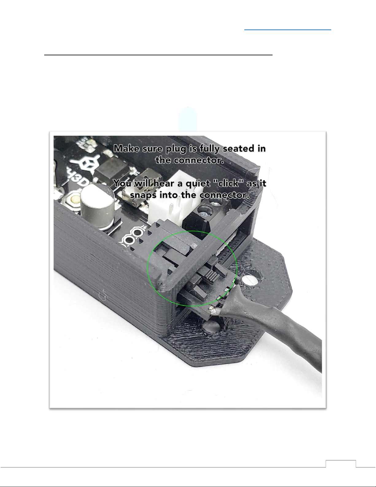
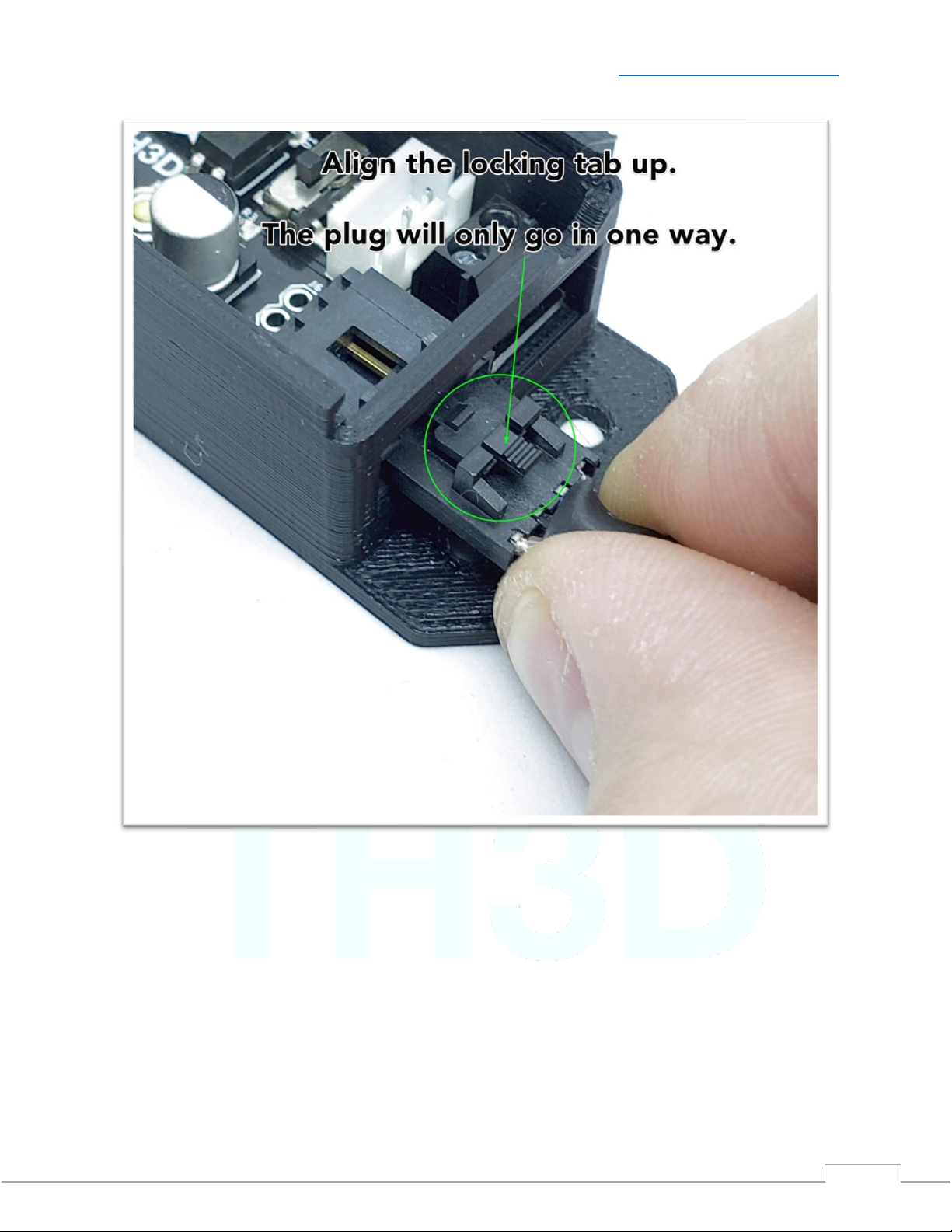
Sensor Connector Wiring
When disconnecting the EZABL Pro sensor wiring you must press the locking tab to release the
plug from the EZABL Pro Board. With the locking tab pressed use your other fingers to grasp the
sides of the plug and pull out. Do NOT use the wires to pull the plug out of the socket. Do NOT
try to remove the plug from the socket without first pressing the locking tab down to release
the tab. The picture below shows where the locking tab is. If wires are pulled out of the
connector due to mis-use this is not covered under warranty and all connectors are checked
before shipment to ensure they are fully crimped.
Table of contents


