3DBNZ ATLAS 4070 User manual

USER MANUAL
ATLAS 4030
ATLAS 4070
This guide will take you through the steps to set
up and operate your 3DBNZ ATLAS 3D printer.
Version 1.3
Revision A

TECHNICAL SUPPORT
For any questions or problems with
3DBNZ products, please contact us at:
3DBNZ
Ul Wilcza 4
Ustka 76-270
Poland
www.3dbnz.com
LIST OF CONSUMABLE COMPONENTS
This document lists the Consumable
components that, for its natural
deterioration, are excluded from the
Warranty:
Nozzle (Hotend), Bowden
Tube, Hotbed Glass, Filament Spools,
Printed Parts.
3DBNZ grants this Warranty to the ATLAS brand Product users.
This Warranty is only valid in the country where the
p
roduct has been
purchased originally, as long as it is member of the European Union,
Iceland, Norway, Switzerland, Liechtenstein or Turkey. Otherwise,
review the Warranty for non EU countries.
3DBNZ guarantees that, within the Warranty Period, 3DBNZ or an
authorized service company will correct, in a reasonable commercial
time, the claims related with the non-conforming Product according
to the following clauses.
WARRANTY PERIOD
The Warranty Period starts when the Product is rst delivered to the
end-user.
The Warranty period lasts twelve (12) months.
Both the parts that suer wear and tear due to the normal operation
of the Product and the “Consumable” elements are not covered by
this Warranty.
The present Warranty is invalidated in case of incurring in any of the
cases exposed in the Exclusions chapter.
In case of resale, repair or substitution of the Products the Warranty
is not extended. The repaired or substituted parts are covered until
the end of the Warranty Period or during six (6) months, depending on
which date is later.
READ THE MANUAL
BEFORE POWERING ON
THE 3D PRINTER
!
2
ATLAS SERIES INTRODUCTION

ATLAS SERIES Index
SAFETY . . . . . . . . . . . . . . . . . . . . . . . . . . 4
Safety Guidelines . . . . . . . . . . . . . . . . . . . . 4
First Aid . . . . . . . . . . . . . . . . . . . . . . . . . . 4
Intended Use . . . . . . . . . . . . . . . . . . . . . . . 4
Symbols and Warning Labels . . . . . . . . . . . . . 5
TECHNICAL SPECIFICATIONS . . . . . . . . . . . . . . . . 6
Dimensions . . . . . . . . . . . . . . . . . 7
SHIPPING CRATE CONTENTS & UNPACKING . . . . . . . . . 8
Contents . . . . . . . . . . . . . . . . . . 8
Work Environment . . . . . . . . . . . . . . . . . . 9
INITIAL SETUP . . . . . . . . . . . . . . . . . . 10
Product description . . . . . . . . . . . . . . . . . 10
Connectors . . . . . . . . . . . . . . . . . . . 10
Powering On . . . . . . . . . . . . . . . . . . . 12
Sensor Verication . . . . . . . . . . . . . . . . . 12
Testing the axis . . . . . . . . . . . . . . . . . . . . 12
USB Connection . . . . . . . . . . . . . . . . . . . . . 13
Leveling the Bed . . . . . . . . . . . . . . . . . . . . 14
Load Filament . . . . . . . . . . . . . . . . . . . . . .15
Extruder Test . . . . . . . . . . . . . . . . . . . . . .15
Unload Filament . . . . . . . . . . . . . . . . . . . . . .16
Change Filament . . . . . . . . . . . . . . . . . . . . . .16
Prepare Print Bed . . . . . . . . . . . . . . . . . . . . . .16
Heat Print Bed . . . . . . . . . . . . . . . . . . . . . . 16
OPERATING . . . . . . .17
Test Print . . . . . . . . . . . . . . . . . . . . . .17
Changing the Nozzle . . . . . . . . . . . . . . . . . 18
Cleaning the Nozzle . . . . . . . . . . . . . . . . . . 19
Printing Via SD Card . . . . . . . . . . . . . . . . . . 19
Printing Via USB Connection with Computer . . . . 19
LCD Control Unit Operation . . . . . . . . . . . . . 20
SOURCE FILES . . . . . . . . . . . . . . . 21
Typical Work Flow . . . . . . . . . . . . . . . . . . . .21
PREPARING FILES FOR USE . . . . . . . . . . . . . . . .22
Converting 3D model to .stl . . . . . . . . . . . . . . 22
Converting .stl to .gcode . . . . . . . . . . . . . . . 22
Basic slicing parameters . . . . . . . . . . . . . . . 23
Start Gcode . . . . . . . . . . . . . . . 23
End Gcode . . . . . . . . . . . . . . . 23
3D PRINTING MATERIALS . . . . . . . . . . . . . . . . .24
Recommended Temperatures . . . . . . . . . . . . 24
Vendors and Manufacturers . . . . . . . . . . . . . 24
Storage Recommendations . . . . . . . . . . . . . . 24
Safety Considerations . . . . . . . . . . . . . . . . . 24
First Aid . . . . . . . . . . . . . . . . . . . . . . . . . 24
PRINTING TIPS . . . . . . . . . . . . . . . . . . . . . 25
Measuring Filament . . . . . . . . . . . . . . . . . . 25
The Importance of Temperature . . . . . . . . . . 25
Seasoning the Nozzle . . . . . . . . . . . . . . . . . 25
Getting a good First Layer . . . . . . . . . . . . 26
Orienting the Part . . . . . . . . . . . . 26
SUPPORTED COMMANDS . . . . . . . . . . 27
WARRANTY, SERVICE, AND SUPPORT . . . . . . . . . . 29
Return Policy . . . . . . . . . . . . . . . . . . 29
Terms and Conditions of Service. . . . . . . . . . 29
EU Warranty . . . . . . . . . . . . . . . . . . 30
Non Eu Warranty . . . . . . . . . . . . . . . . . . 31
3

To avoid potential residual risks the user should read and understand the following
safety measures ( you are strongly advised to read this before using the machine ).
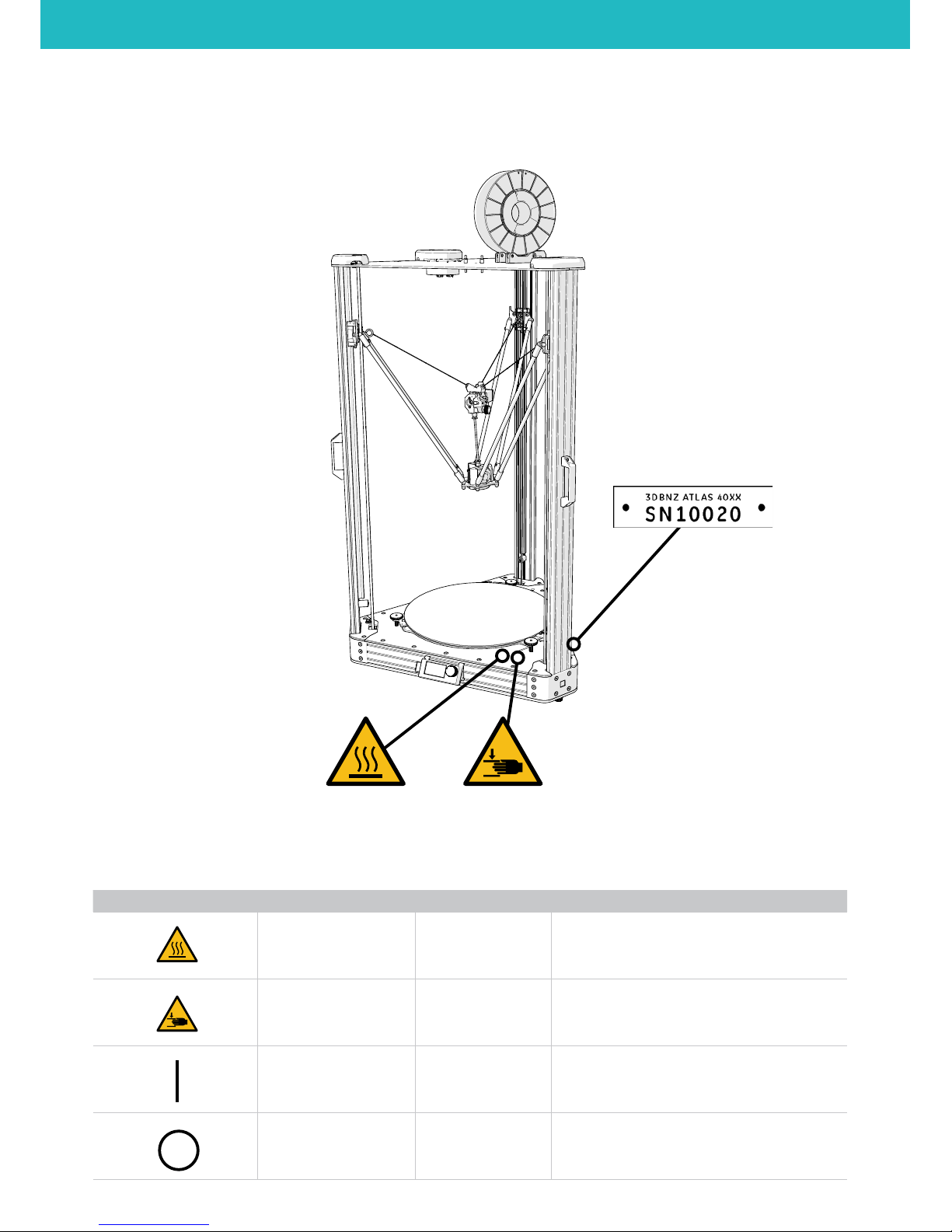
To highlight the areas where extra care should be taken, safety alert stickers have been
axed to the relevant parts of the machine to warn the user of potential hazards.
Any modications made to the machine without the manufacturer´s approval will
invalidate the product´s warranty.
Consequently, BNZ3D ARE EXEMPT FROM ANY LIABILITY IF THE USER DOES NOT FOLLOW
THE INSTRUCTIONS FOR USE:
SAFETY GUIDELINES & WARNINGS
The following safety guidelines, as well as the instructions within
this user manual, ensure the safety of the user while operating and
maintaining the ATLAS printer. If the printer is not operated as
specied, the operator’s safety may be compromised.
First Aid
• All operators should have access to rst aid equipment and
know how to use it.
Installation
• Connect the printer to the safety-certied power cord supplied
with the machine. The electrical outlet should be near the
printer and easily accessible.
• Never connect the printer to an outlet that does not have a
ground wire. Disconnecting the ground wire may result in
electric shock.
Operation
• The 3DBNZ ATLAS printer generates high temperatures in the
print nozzle and the print bed—do not touch when hot. Allow
the unit to cool before touching.
• Do not set objects on the heated print bed. Do not lean or
stand on the print bed. Doing so may cause injury to the
operator.
• Due to high temperature outputs and moving parts, the
location where the printer is operating should be equipped
with working smoke and ame detection.
• The 3DBNZ ATLAS printer melts material during printing. Some
materials may require ventilation.
• Do not leave the 3DBNZ ATLAS printer unattended while in
operation.
• The 3DBNZ ATLAS includes linear actuators that move in
multiple directions at variant speeds. When in motion, they
may cause injury.
• Do not place head or any other body part near the print head
or nozzle, as injury may occur if pinched between the print bed
and the nozzle.
• In case of emergency, unplug the unit from the electrical
outlet.
Maintenance
• All maintenance shall be performed according to the
manufacturers guidelines and instructions. Failure to follow
the guidelines may cause injury.
• When maintaining equipment that is hot, wear gloves to avoid
injury.
INTENDED USE
Each 3DBNZ ATLAS 3D printer is tested, prior to shipment, to ensure
proper functionality.
• This printer is intended for professional use by an operator
with the ability to read instructions, having basic/low level
knowledge of electronics, mechanics, and computers in
general.
• Intended for printing 3D objects with materials manufactured
for the FFF—fused lament fabrication—type of 3D printing.
• To be operated under normal operating conditions as specied
within this manual.
• Not intended to be used by children or persons not familiar
with the operating and safety instructions. Use by unqualied
persons may be dangerous to the user and/or damaging to
the printer. Printer damage due to mis-use is not covered by
the warranty.
• Any modications to the 3D printer are at your own risk and
will void the warranty. The manufacturer cannot be held
responsible for modications made by other persons.
ATLAS SERIES Safety Guidelines & Warnings
4

SAFETY AND WARNING SYMBOLS
The following stickers have been axed to the printer to warn users about the hazardous areas of the machine, and actions which are not
recommended as they will stop the machine from working properly.
Machine serial
Warning Symbol Meaning Location Comments
WARNING HOT SURFACE • Print nozzle
• Print bed
A hot surface is located in the vicinity ( do not
touch ).
CRUSHING OF HANDS
• X axis
• Y axis
• Z axis
When in motion, the Altas linear actuators that
move in multiple directions at variant speeds may
be a pinch hazard ( low risk due to force limitation )
ON • Rear panel of
electrical box Turns the machine on.
OFF • Rear panel of
electrical box Turn the machine o.
ATLAS SERIES Warning Symbols
5

Model name ATLAS 4030 ATLAS 4070
MECHANICS
Chasis Aluminium
Enclosure PLEXYGLASS
Kinematics Steel guide with recirculating balls, anti backlash magnetic joints
Motors Nema 23 1.8° 1/16 step
Motion transmission GT2 6mm belt
Endstops Optical
Build surface Tempered Glass
DIMENSIONS
General Dimensions 64 x 63 x 105 cm 70 x 65 x 148 cm
Weight 45 Kg (without lament spools) 65 Kg (without lament spools
ELECTRICAL
Input 100-120 VAC / 200-240V 50-60Hz
Energy consuption 400W Heaters on - 36W Standby
System voltage 24v
TEMPERATURES
Operating temperature 15-35°C
Stocking 0-30°C
Hotend max 290° C
Heated bed max 100° C
Hotend cooling 30x30x10 24v fan
Internal electronics cooling 80x80x20 24v fan
INFORMATIONS
Manufacturing technology Fused lament fabrication (FFF)
Printing volume Cylindical 400mm diameter x 300mm
height
Cylindical 400mm diameter x 700mm
height
Nozzle size 0,4 mm (standard) 0,15 / 0,25 / 0,3 / 0,5 /
0,6 available
Layer height 0,05 mm < 0,5 mm
Repetability XY 0,02mm / Z 0,05
Filament diameter 1,75 mm
Compatible materials ABS, PLA, PET, Nylon, FLEX, Polistirene,
Wood, Carbon, Experimental
SOFTWARE
CPU 32 bit
Host operating system Windows XP-7-8-10, Mac OSX, Linux
Slicing Software Cura, Simplify3D, Kisslicer, etc.
Firmware Smoothie
File format .gcode
CONNECTIVITY
LCD LCD panel with rotary encoder (autonomous operation)
USB Type C
TECHNICAL SPECIFICATIONS
ATLAS SERIES SPECIFICATIONS
6

DIMENSIONS
Printer dimensions illustrated below.
Note: Dimensions are not considering the lament spool
1047,77
579,89
641,55
625,78
ATLAS 4030
1447,77
579,89
641,55
625,78
ATLAS 4070
ATLAS SERIES DIMENSIONS
ATLAS 4030
ATLAS 4070
7

CONTENTS
• ATLAS 40xx 3D printer
• LCD Control
• Spool roller
• Power cord EU or UK
• USB cable
• Dimax ( Optional )
• SD Card ( Optional )
• Nozzle 0.6mm ( Optional )
UNPACKING THE PRINTER
The 3DBNZ ATLAS printer will arrive in 1 industrial strength wood crate. Please take a moment to review the unpacking procedure to
ensure the safety of the unpacker, as well as the printer.
• The optionals ordered together with the device could be inside the package or in separate package.
• Save the original package to be reused in case of device return to the manufacturer.
• Take great care not to break or splinter the printing surface which is made of glass.
CAUTION: The unit is heavy. Care must be taken to assure safety of machinery and operators.
Take care if using sharp tools for unpacking
• A phillips head screw driver is required.
1. Unscrew the screws and remove the front panel.
2. Carefully remove bracing, supporst, and /or tie downs what are used to secure the product for shipping
3. Remove the possible styrofoam if any before sliding out the device.
4. Bring the device out with care using the handles on each of the three sides.
• Replacement PTFE tube 235 mm
• Replacement Hotend fan
• Replacement Pusht extruder side
• Replacement Push t hotend side
ATLAS SERIES Shipping Crate Contents & Unpacking
8

INTRODUCTION
Congratulations on the purchase of your new device. With it you have chosen a high quality product.
During production, this equipment has been checked for quality and subjected to a nal inspection.
The functionality of your equipment is therefore guaranteed.
PRELIMINARY CHECKS
Before using, please check that the device is not damaged due to the transportation or due to the condition of preservation. To be checked
if all standard components and the optional are present in the package. In case of damages, notify the claim to the carrier and inform the
authorized dealer or manufacturer.
INSTALLATION
The device installation is easy, it is recommended to be done by skill people and to follow the instructions.
CAUTION: Do not install the device near to heaters or liquids.
The device should be positioned on a stable and at surface (not supplied), able to stand the device weight and to absorb the vibrations.
• If the surface is not at use the three regulation feet under each tower.
On the right side of the device is positioned the switch, this side should be easy accessible, on the lower side of the device there are the air
inlets and the fan that provides to the correct cooling of the electronics and the motors. Keep the cooling air inlets clean from obstacles.
The lament should be positioned on the upper part of the device using its spool roller that is included in the supply.
In case of shelves or wall too near to the device it could be alternative positioning of the lament reel, but it is mandatory that the lament
is easy accessible and without having obstacles to the pulling of the lament by the extruder.
The inner lower part of the device, made by glass, has an heating system, for an optimal work result it is suggested that the temperature in
the environment to be about +20C°. Lower or higher temperature could aect the nal result of the prints.
ATLAS SERIES Work Environment
9

PRODUCT DESCRIPTION
3D printing, or additive manufacturing, is a process of making three-dimensional objects of a variety of shapes and sizes from a digital
model. 3D printing is achieved using an additive process, where successive layers of material are heated and melted at the nozzle,
extruded and laid down on the build platform ( also known as Fused Filament Fabrication (FFF). )
The printer is capable of using any material manufactured for FFF type 3D printing, provided the melt temperature and print bed
temperature requirements are within the specications of the ATLAS outlined in this manual.
The ATLAS is capable of carrying out the additive manufacturing process under open source controls, via 3D model output in the .gcode
format. It can be operated using the USB computer interface or independently with the LCD control unit and SD card.
Layer Fan
Z Probe
Extruder 1
Not installed
End Effector
Extruder 0
Layer Fan
Z Probe
Extruder 1
Not installed
End Effector
Extruder 0
CAUTION: Turn OFF the machine before
connecting or disconnecting any cable.
Look at the orientation notch to align the connector to
the plug, never use too much force.
1. End Eector: 8 pin
2. Extruder 0: 4 pin
3. Extruder 1: 4 pin
4. Layer Fan/Zprobe: 4 pin
5. Not Installed
CONNECTORS
ATLAS SERIES Initial Setup
Extruder
Eector
Hotend
Carriages
Connector Box
Filament Spool
Build Plate
LCD control
Handles
Magnetic Rods
Endstop cover
10
1
23
4

In order to ensure the safe packaging and transport of your printer some of the components have been sent unassembled.
Before starting to print with the 3DBNZ Atlas printer you need to assemble them in order to complete the setting up process.
If you have any queries while assembling the machine, please contact 3DBNZ technical services.
Follow the steps below to prepare the printer:
1. LCD PANEL INSTALLATION
Connect the two ribbon cables, to the LCD control unit and install it
on the front of the machine. Cables are numerated 2 and 3.
2. BUILD PLATE
Remove the 3 clips that hold the glass in place during shipping and
any other styrofoam.
3. FILAMENT ROLLER
Put the spool rollers on the top of the machine. Check if the spool
turns freely and make sure is stable and secure.
4. END EFFECTOR
The End eector comes installed. If you remove it make sure the
rods are parallel to each other when re-installing.
ATLAS SERIES Initial Setup
11

POWERING ON
1. Plug the power cord into the power outlet.
2. Turn the switch on the ON position
ENDSTOPS SENSORS VERIFICATION
The ATLAS printer has three position sensors–one for the X tower, one for the Y tower, and one for the Z tower. We will name them alpha,
beta and gamma.
These sensors allows the printer to know its home position and prevent the hotend and/or the actuators from traveling beyond the
designated print area–which can cause serious damage or breakage to the extruder, glass, and/or the mechanical hardware on the
printer.
IMPORTANT: Each ATLAS is tested prior to shipping, but it is important to verify the functionality of the sensors in case of damage or
movement during the shipping process.
1. Hold a piece of opaque material into each sensor. The red light should turn o when triggered.
2. Using the LCD controls check if the CPU are receiving the signal when triggering each endstop sensor
LCD > PROBE > STATUS
Contact 3DBNZ if sensors are nonoperational. Do not attempt to operate the printer.
TESTING THE AXIS
1. Check that nothing blocks the axis mechanisms (belts, pulleys etc)
2. Ask the printer to go to its know position “home“
LCD > PREPARE > HOME ALL AXIS
CAUTION: While the eector is in the home position you CANT move in XY plane as the carriages dont have enough space to
accomplish that, take care when Jogging the postion of the end eector manually.
You should never move the eector by hand, use the carriages instead.
After a move command is sent to the printer the motors remains energized to hold their position, you can turn o the motors:
LCD > PREPARE > MOTORS OFF
ATLAS SERIES Initial Setup
12

USB CONNECTION
Connection to a host is not necassary to print, if you want more control on the machine use a host software to send Gcodes.
From March 2014 ATLAS don’t require drivers. The new rmware supports USB communication (as HID device) and internal SD drive
natively, without any necessary les.
1. Just plug USB cable, and wait until all devices are discovered by your system.
2. It is recommended to open Device Manager (if using Windows), and monitor installation there. You should see ‘Smoothieboard USB
Serial’ appear during the process and the assigned COM port.
3. After automatic installation a new disk drive named ATLAS should be discovered, where all conguration and rmware related les
are stored. The disk can also store g-codes for printing.
4. Important: please copy all contents of the SD card drive as soon as you can (backup).
5. After that, you can connect to the machine using a host of your choice, which can be for example pronterface
http://www.pronterface.com/
6. In Pronterface, select the correct COM port and click Connect.
If you have problems with the connection, then unplug/plug USB cable.
Or press RESET on the printer, wait and repeat all steps above.
If you still encounter connection issues try with another computer.
CAUTION: Do not write to internal memory while printing.
Make sure the ATLAS is plugged into the same outlet as the PC you are connected to, otherwise you can get ground loops.
ATLAS SERIES Initial Setup
13

LEVELING THE PRINT BED
Prior to rst printing is imperative to check for correct nozzle height.
IMPORTANT: improper height will result in a fail print or damaged glass and/or nozzle.
Setting the build to low and the lament will not stick to the build plate, setting it too high the nozzle will be blocked and the
lament will jam.
To change the height of the build plate use the three knobs. Turn clockwise to lower the build plate and counteclockwise to raise it.
1. Each regulation knob must have the screw above the knob of 1mm. This will give enought room for regulation up and down later.
2. Home the eector so the printer know its position in space :
LCD > PREPARE > HOME ALL AXIS
3. With a piece of regular paper on the build plate move the eector down until you get the nozzle near the glass barely pinching the
paper. Go down until you can feel slight resistance while sliding the paper, for ne adjustment you can select ner jog increments
LCD > JOG > MOVE 1mm > MOVE Z
4. Tell the printer how far in Z is the build plate from home position:
LCD > CUSTOM > SET Z0
Now the printer will home and store the new height information ( into Cong Override le on the internal memory )
5. Move the eector to Z0
LCD > CUSTOM > CALIBRATE CENTER
6. Check and correct build plate height at each tower beginning with the alpha tower
LCD > CUSTOM > CALIBRATE ALPHA
LCD > CUSTOM > CALIBRATE BETA
LCD > CUSTOM > CALIBRATE GAMMA
7. Repeat step 6 to rene the calibration as each regulation aects the others two
To maximize adhesion It is reccomended to ne adjust the bed height regulation on the y when printing rst layer.
Take into account temperature varations, for best result calibration should be run with a hot machine as elements change dimensions
with temperature.
1,00 mm
ATLAS SERIES Initial Setup
14

LOAD FILAMENT AND EXTRUDER TEST
Position the lament spool roller on top of the printer. Guide the lament through the rst PTFE tube then into the extruder.
1. Lower the End eector to make the loading operations easier.
LCD > CUSTOM > LOADING POSITION
2. Pre heat the 3D printer
LCD > PREPAE > PREHEAT
3. Set the nozzle temperature 10°C above the reccomended for the used material.
LCD > PREPARE > SET TEMPERATURES > HOTEND
4. While waiting temperature to stabilize load the lament
5. Push the lament by hand into the extruder until you see material owing from the nozzle.
The lament must ow consistetly without applyng to much force. Adjust temperature so the force needed to push the lamnent in is not
too high.
6. Turn the knob until the extruder block is fully closed. IMPORTANT: Do not overtight the knob
Depending on lament elasticity you can adjust the tensioner force by turning the two hex screws.
Tighten for hard materials and loosen for softer ones.
7. Test for consistent ow by extruding 4/5 timens 10mm of lament
LCD > CUSTOM > EXTRUDE 10mm
CAUTION: Do not RETRACT more than 3mm of lament or the hot end will jam.
ATLAS SERIES Initial Setup
15

UNLOAD FILAMENT
1. Preheat the hotend to 180°C (minimum)
2. Open the extruder tension block to release the hob
3. Pull the lament out ( use a fast moovment to reduce stringing )
Store lament in a cool place. Keep temperatures below (50° C). Keep material in sealed container or bag with moisture-absorbing
desiccant.
CHANGE FILAMENT
Filament can be changed at any time ( when the printer is idle or mid-print ).
• The hotend must be heated to 180º C (minimum) to remove or add lament.
• When printer is idle (not printing): Open the extruder tension block to release the hob and pull out existing lament, then follow the
Loading Filament instructions.
• When the printer is mid-print: press the main button on the LCD Control Unit, select CUSTOM , select SD Suspend. This manually puts
the printer into standby. Then follow the Loading Filament instructions.
• To resume the print press the main button on the LCD Control Unit, select CUSTOM , select SD Resume.
HEAT THE PRINT BED
The print bed on the ATLAS printer is heated to provide better adhesion of your printed parts. Each material you use will likely require a
dierent bed temperature.
• For easy removal of large or small parts, turn the bed temperature down to 20° C. You will hear the plastic loosening and the part will
pop o the print bed.
• Operate the temperature of the print bed through the LCD control unit or with 3D printing software.
See the Recommended Temperature table
CAUTION: For the safety of the user, use extreme caution when working with heated machinery.
PREPARE THE PRINT BED
Prepare the build area for printing. In order for your prints to adhere to the glass ( it needs to be clear of debris and sticky ) spray a good
amount of Dimax xative spray onto the build area.
Cover the entire area that your print will touch. Repeat this process between prints to remove lament particles and other debris, as well
as prepare the bed for the next print.
This is not the only method available. Other suggestions include: painter’s tape, glue stick, and hairspray.
Note: 3DBNZ recommends using Dimax or 3DLAC only. Any scented hairspray may contain oils and cause adherence
issues on the print bed.
Do not use glass cleaner or alcohol on the glass. Doing so will make adhesion very dicult.
For big prints the xative spray should be sprayed while the glass build plate is removed from the printer in order to avoid contaminations
of sticky material on the delta motion system.
• To remove the glass turn clockwise the glass retention knob to release pressure of the spring
• Clean the aluminium contact surfaces and the back of the glass before installing it into the printer
ATLAS SERIES Initial Setup
16

TEST PRINT
1. Spray a thick coat of Dimax or 3DLAC xative glue on the glass build plate while is cold.
2. Preheat the build plate to at least 45°C for PLA and 90°C for ABS.
LCD > PREPAE > PREHEAT
and
PREPARE > SET TEMPERATURES > BED
3. In the internal memory there are some test objects rady to be printed.
LCD > PLAY > SD > 3DBency.gcode
4. While printing the rst layer adjust the bed levelling knobs on the y until you get the optimal rst layer adhesion.
5. Wait the printer to cool down before removing the printed object
PRINT YOUR OWN GCODE
You can print your Gcodes in 3 dierent ways:
1. Load the Gcode into the internal 2GB memory using the USB cable ( slow transfer / safe to print )
2. Load the Gcode on a FAT 32 formatted SD, insert the SD into the LCD ( fast transfer / safe to print )
3. Stream the Gcode trough the USB connection using a host software like Pronterface ( not safe for long prints )
CAUTION: When creating your own gocdes remember to put the homing command, G28, into your software start routine.
Do not turn o the printer until the nozzle is below 50°C.
ATLAS SERIES Operating
17

CHANGING NOZZLE
The extruder is hot, handle with care
Do not touch the heater cables with metal while heating is on.
Do not turn o the machine if the hotend temperature is above 50°C
Tools needed:
• 7 mm wrench or Socket Wrench
• Crescent wrench
When installing the nozzle make sure that the nozzle and the heat break mate up inside the heater block, this is needed to prevent leakage
and lament jams.
An indication of succesful mating is resulting gap between the nozzle and the heater block after thightening the nozzle.
1. Preheat the hotend
2. Unload the lament
3. Set the extruder nozzle temperature to 200º C. This will melt any plastic inside the extruder and loosen the nozzle.
4. Once the temperature has reached 200º C, use a crescent wrench and 7 mm wrench to remove the nozzle. Use the crescent wrench
to hold the base steady and not able to rotate. Use caution—nozzle is hot!
5. Once nozzle is removed select the replacement nozzle. Nozzle size can be determined by inspecting stamped numbers along the side
of the nozzle.
6. Once new nozzle has been selected, hand thread it into the extruder.
7. Then use the wrench and crescent wrench to tighten the nozzle into the assembly, only tighten until snug. DO NOT OVER TIGHTEN.
8. Once nozzle is tightened, set the extruder temperature from 200º C to 280º C. This will heat up the nozzle and ensure it has a tight t.
9. Once the temperature has reached 280º C, use the wrench and crescent wrench to tighten the nozzle so it is snug.
GAP
HEATBREAK AND
HEATER BLOCK ALIGNED
HEATBREAK AND
NOZZLE MUST MATE
When reinsterting the PTFE tube make sure its fully inside
the extruder.
ATLAS SERIES Operating
18

CLEANING THE NOZZLE
Use extreme caution when maintaining or operating heated machinery. The nozzle must be heated to 180º C ( minimum ) when cleaning.
When to clean the nozzle:
• When lament is not owing smoothly
• When lament is not being extruded appropriately
• When changing material type
• Periodically between large prints—preventative maintenance
How to clean the nozzle:
Canola oil treatment:
1. Dip 20 mm of lament into oil and shake o excess
2. Heat nozzle to 250 - 260º C
3. Push lament through the extruder and nozzle by hand
4. Extrude 200 mm of lament
5. Repeat 3-4 times
CAUTION: Wear heat resistant gloves
Use appropriate tools for all cleaning and maintenance
ATLAS SERIES Operating
PRINTING VIA SD CARD
The ATLAS can be operated independently with the LCD Control Unit and an SD Card.
Select PLAY on the LCD Control Unit, then choose the .gcode le you wish to print
PRINTING VIA USB CONNECTION WITH COMPUTER
The ATLAS can be operated through the 3D printing software’s Manual or Machine Control Panel.
Follow the Connect the USB instructions on page 13.
Once connected, the printer can be operated via the computer and software interface.
NOZZLE SIZES AND TYPES
Nozzle Size Brass Hardened Steel Stainless Steel
0.15 mm High Precision - Slower Prints •
0.25 mm High Precision - Slower Prints • • •
0.30 mm • • •
0.35 mm • • •
0.40 mm Balanced Nozzle - Supplied by Default • • •
0.60 mm • • •
0.80 mm Lower Precision - High Speed • • •
undrilled •
19

LCD CONTROL UNIT OPERATION
There are three main functions of the LCD Control Unit:
1. Prepare the printer for printing
2. Manual control—both prior-to and during printing
3. Starting a print from the SD card
Use the button / knob combination to select and scroll through the screen options.
ATLAS SERIES Operating
PLAY Opens the PLAY menu
SD... List of .gcode les from internal memory
card
EXT... List of .gcode les from external
memory card
JOG Opens Move Axis menu
Back... Returns to main menu
Move 10 mm Opens Move Axis 10 mm menu
Move X Moves X axis in increments of 10 mm
Move Y Moves Y axis in increments of 10 mm
Move Z Moves Z axis in increments of 10 mm
Move 1 mm Opens Move Axis 1 mm menu
Move X Moves X axis in increments of 1 mm
Move Y Moves Y axis in increments of 1 mm
Move Z Moves Z axis in increments of 1 mm
Move 0.1 mm Opens Move Axis 0.1 mm menu
Move X Moves X axis in increments of 0.1 mm
Move Y Moves Y axis in increments of 0.1 mm
Move Z Moves Z axis in increments of 0.1 mm
PREPARE Opens prepare menu
Home all axis Homes the machine to x0, y0, z0
Set Home DO NOT USE Sets home position
Set Z0 DO NOT USE Sets temprally new bed
height
Motors O Turn o the motors
Preheat Heat the hotend to 180°C and the bed
to 60°C
Cooldown Turn o any heating
Extruder Opens the Extruder menu
Extrude 5mm Extrude 5mm of lament
Retract 5mm Retract 5mm of lament
Settings... Opens the Extruder Settings menu
E steps/mm Number of steps required for the
extruder to wmove 1 mm of lament
Filament d Sets the lament diameter ( only for
volumetric extrusion )
Flow Rate Sets extruder factor/multiplier for all
extruders—expressed in percentage
Accel Sets the extruder stepper accelleration
Retract Le Sets the retraction lenght ( only for
volumetric extrusion )
Set Temperatures Opens the Temperatures menu
Back... Returns to previous screen
Hotend Sets the hotend temperature
Bed Sets the bed temperature
CUSTOM Opens custom menu
Layer Fan ON Turn on the layer fans
Layer Fan OFF Turn o the layer fans
Go to load Position Lower the extruder for easy access
SD Suspend Pause the current print
SD Resume Resume the current print
E0 Extrude 10mm Extrude 10mm of lament using
extruder 0
E0 Retract 10mm Retract 10mm of lament using
extruder 0
Calibrate CENTER Move the nozzle to the center of the bed
Calibrate ALPHA Move the nozzle near the alpha tower
Calibrate BETA Move the nozzle near the beta tower
Calibrate GAMMA Move the nozzle near the gamma tower
Save Z0 Save the current position as Z0
CONFIGURE Opens congure menu
Accelleration Sets the global accelleration for XYZ
moovments
X Steps / mm
Number of steps required for the
stepper motor to move 1 mm in the X
direction
Y Steps / mm
Number of steps required for the
stepper motor to move 1 mm in the Y
direction
Z Steps / mm
Number of steps required for the
stepper motor to move 1 mm in the Z
direction
Z Home Ofs Sets the oset
Contrast Sets the LCD contrast
20
This manual suits for next models
1
Table of contents