Thaler KE-SP 60100 GM User manual

Operation Manual
Cable pulling winch
KE-SP 60100 GM
Diesel motor (Kohler)
Electronic Measuring System TM 3000
Indicate Serial Number W09SP5103EET06517
!"#
$%&"''(###%
)!"#
$%&"''(###(
*+,-.
/+000-.

Jakob Thaler GmbH
25335 Elmshorn GERMANY

Jakob Thaler GmbH
25335 Elmshorn GERMANY
This symbol calls attention to important safety instructions which, if not
followed, could result in serious personal injury or death.
Read, understand and observe all safety information and instructions in this manual,
and on safety decals on the KE-SP 60100 GM before using it. For safety reasons, read
the operators manual carefully and exercise caution while using the winch.
Please note specific safety requirements as explained by procedures called out in this
manual. Failure to follow these instructions could result in serious personal injury
or death.
All tools, materials and equipment manufactured and supplied by Jakob Thaler GmbH
are designed to be used by qualified and trained personnel only. Jakob Thaler GmbH
will not be held liable for any injury or damage to either people or property resulting from
the misuse of Thaler equipment.
Please save this user's guide for future reference and have it available to all
operating personnel. Personnel should thoroughly read this operating manual.
Warning:
Do not start, operate or service
machine until you read and
understand operator’s manual.
Failure to do so result in serious injury.
Warning:
Moving cable can crush and cut.
Do not operate with panel open. Shut off machine
before servicing, cleaning and inspection.
Warning:
Battery explosion can blind.
Acid can blind and burn.
Read manual before servicing
Warning:
Fuel and fume can explode and burn
No smoking - No fire - Stop engine

Jakob Thaler GmbH
25335 Elmshorn GERMANY
Warning:
Stay clear of front and rear while pulling cable
Equipment may move in either direction suddenly when under tension.
Warning:
Warning:

Jakob Thaler GmbH
25335 Elmshorn GERMANY
Follow all safety instructions concerning safety and possible danger.
Do not modify or remove the safety devices or warning labels of this machine. Keep all labels
regarding safety and possible danger on the machine in good, readable condition. Special care is
required before and during the safety check.
Every crew member should fully understand the safety measures required for the operation and
should be capable of following these regulations individually.
The KE-SP 60100 GM is manufactured to the current technical safety-relevant regulations.
Nevertheless, the use of the machine may represent a danger to the health and life of users or third
parties. Always ensure that you pay particular attention to warnings, safety labels and instructions.
Read Operators Manual
Before starting the machine, fulfil
l all safety related requirements. All
personnel should thoroughly read this operating manual.
Follow all safety instructions concerning safety and possible danger. Do not
modify or remove the safety devices or warning labels of this machine.
Keep all labe
ls regarding safety and possible danger on the machine in
good, readable condition. Special care is required before and during the
safety check.
Every crew member should fully understand the safety measures required
for the operation and should be capable
of following these regulations
individually.
Call Before You Dig
Check the existence and exact position of buried pipe and cables by
contacting the respective utilities or owners of networks. The exact and
definite existence and position of buried cabl
es and pipes should be defined
by trial pits or using cable and pipe detection equipment or other means.
Cable Strike
Should you accidentally hit an electrical cable, immediately leave the site,
ensure no one enters and contact the electrical company t
o turn off the
supply.
In case of a cable strike, the danger resulting from that damaged electric
cable can only be evaluated following detailed information by the respective
electrical company. Never rely on your own knowledge as to types of
cables, safet
y measures and protective measures that may not be correct
for the type of cable encountered. Always consider cables to be “live” and a
potential danger to life. Do not re-enter the site until authorized by the
electrical company.
No Loose Clothes
Do not wear loose clothes or long hair. Danger of body injury by loose
clothes or hair being caught in the moving parts of the machine.

Jakob Thaler GmbH
25335 Elmshorn GERMANY
Personal Protective Equipment
The operating crew should always wear the appropriate safety
equipment, safety shoes
/boots, hard hat, safety glasses, gloves, ear
protection etc.
Operation by Qualified Personnel Only
Operation of the winch should be carried out by suitably trained,
qualified, and certified personnel only. New operators or operators in
training should be working under the constant supervision of a qualified
person. Personnel operating the winch should have sufficiently
studied the operating manual.
Skin Burning Caution
This item can be hot or cold. Do not touch as burns may result.
Winch Maintenance
Use the machine only if it is in perfect working order and after studying
the operating manual, particularly the safety-
related sections. Always
check the machine and its accessories for unwanted movements. To
guarantee long life, regular maintenance is essential. Inadequate or
infrequent repair and maintenance operations may lead to accidents,
downtime and costly repairs of the machine.
During repair and maintenance operations always follow the respective
safety recommendations. Repair and maint
enance operations are
restricted to trained and certified staff only.
Transporting the KE SP 60100
Danger of accidents. Do not overload the transportation vehicle.
Starting & Exit Pit Excavation
Make sure that start and exit pits are excavated and sh
ored as
necessary to comply with the regulations and guard against collapse.

Jakob Thaler GmbH
25335 Elmshorn GERMANY
The KE-
SP 60100 GM constant tension, variable speed winch is a trailer mounted twin capstan mobile
hydraulic winch used for a variety of ap
plications including cable placing. The winch is comprised of three
major components including the twin capstan assembly, rope storage drum and the engine/hydraulic power
pack
The winch is mounted on a heavy-duty tandem axle trailer fitted with overrun bra
kes for towing safety. The
machine is normally fitted with a ring eye and wired for stop and turn signals and night running lights.
2.
A. Product Identification
Record Identification Numbers.
If you need to contact your service station or Jakob Thaler f
or information on servicing, always provide the
model and serial numbers.
You will need to locate the Identification numbers for the machine. Record the information in the spaces
provided below.
Machine Identification Numbers
Model #__________________
Serial # __________________
Engine Identification Numbers
Model #__________________
Serial # __________________

Jakob Thaler GmbH
25335 Elmshorn GERMANY
B. Control Identification dependent to Model
1 Electronic Recorder TM 3000
2 Engine Control Box
3 Winching Lever
4 Dead Man’s Control
5 Engine Accelerator
6 USB Port
7 Beacon Light
8 Emergency Stop
9 Fuel Gauge
10 Printer
11 TM 3000 On/Off
12 Red Control Lamp Winch Function Off
13 Green Control Lamp Winch Function On
14 Air filter control
15 Ignition Key
16 Set Button
17 Display
When Pressing the set button the display shows:
Engine speed, working hours, service hours, oil
pressure, coolant temperature and engine torque
1
2
3
4
5
6 7
8
7
10
9
11 12 13 14
15
16
17

Jakob Thaler GmbH
25335 Elmshorn GERMANY
B. Control Identification dependent to Model
Rope Payout 0 Pulling in
Winch control lever
As more the lever is pushed in one direction than
higher the line speed increases.
For pulling higher loads it is essential to set the
lever into lower line speed mode.
The operator must maintain a balance between
required pulling force and line speed.
Please note:
High loads = low speed
Low load = higher speed
Dead man’s control
For winching the dead man’s control must be
pressed. Place the control in the holder as
shown in picture.
For leaving the winch for observing the line pull
in the pit take the control and keep the red lever
pressed. As soon as the lever is released
winching function stops automatically.
Diesel engine’s throttle lever.
Pulling the lever increase the engine speed.
Please note:
In most winching application it is sufficient
when the engine runs in medium speed. The
engine generates the highest performance at
1500 rpm.
Only for quick rope pay out the engine
should run with maximum speed of 2700
rpm.

Jakob Thaler GmbH
25335 Elmshorn GERMANY
A. Pulling Force
Winch type
Pulling force
KE-SP 60100 GM
22046 lbs (10 000 kg)
B. Winch Line Specifications
Line diameter
Line length
5/8 in. (16 mm)
3182 ft. (970 m)
C. Engine Specifications
Engine
Power
3-cylinder Kohler diesel engine
56 HP (42 kW)
D. Chassis
Type
Hitch
Weight capacity
Tires
Tandem
Pintle eye
8818 lbs (4000kg)
215/75 R 17,5
E. Winch Specifications
Length
Height
Width
Weight
F. Twin Capstan Assembly
The capstans are of equal diameter and are driven by one or two hydraulic motors. Unlike winches that pull
off the drum, the hydraulic system of the KE-
SP 60100 GM ensures full power output regardless of storage
drum back tension. The line pull is
regulated automatically, giving very smooth operation without jerking or
slack. The capstan and associated parts are machined from low wear, case hardened steel and include
roller bearings.
G. Winch Line Storage Drum
The winch line storage drum is indep
endent of the winch and is driven by a separate hydraulic motor. A
cross groove spindle-
layering device ensures precision rope layering on the drum during operations,
preventing winch line damage.
H. Hydraulic System
The hydraulic power system is comprise
d of a combustion engine, hydraulic pump and motors to operate
capstan and rope storage drum. A separate hydraulic reservoir and, if required an oil cooler allow for
continuous operation with no overheating. The system provides fully automatic winching control.
Hydraulic power is generated by an axial piston pump that is driven by a diesel or petrol engine. The
hydraulic flow from the pump determines the line speed that is infinitely variable by a winching lever. The
hydraulic system is close center circuit ( hydro-static drive).

Jakob Thaler GmbH
25335 Elmshorn GERMANY
Safe Operating Procedures
A. Safety Instructions
For your protection and the protection of others, practice the following safety rules.
1. Read operators manual and safety decals before operating this winch.
2. Only authorized personnel familiar with this winch and its functions to operate.
3. Do not use to lift, support or transport personnel.
4. ONLY pull load in horizontal direction. Do not use to lower or pull equipment vertically.
5. Do not operate until all safety shields are in place and controls function properly.
6. Turn off engine and secure against accidental movement and/or unauthorized start-up if leaving winch
unattended.
7. Keep winch clear of motor vehicle traffic or provide barriers, signs and/or
warning lights.
8. Verify all safety shields are refitted after maintenance.
9. Provide a quality inspection by a qualified specialist at least once a year.
10. Shut off winch and wait for movement to stop before,
servicing, cleaning or inspecting.
11. Only authorized operations personnel to remain near
equipment while cable is pulled under load.
12. NEVER enter manhole or excavation pit while winch is
pulling cable under load.
13. Personal protective equipment is required while operating
this machine. Keep hands, feet
B. Hydraulic Equipment
1. Tighten all connections before applying pressure. Relieve pressure when service unit.
2. Check for leaks with a piece of cardboard. Do not use hands.
3. Do not exceed working pressure of hydraulic hoses.
4. Visually inspect hydraulic system and connections regularly. Service if needed
C. Rope Inspection, Maintenance
(See Appendix A, B)
Transporting The Winch
A. Towing the Winch
In Standard version the KE_SP 60100 GM has an adjustable ring eye to allow the winch to be towed by
vehicles with various height rear bumpers. By turning the lever on the tow bar , the tires will support the load
at a level attitude at most vehicle hitch levels.
1. To change the winch attitude, lower the front jack stand to support the front oft the winch and provide a
level winch attitude. Turn the lever on the towing bar.
2. Raise or lower the hitch to the proper tow vehicle hitch height.
3. Tighten all bolts of the pintle hitch firmly.
IMPORTANT: Winch must be level for safe highway towing.
4. Fit the emergency brake cable to a rigid part of the towing vehicle!
5. Connect winch lights/electrical system to towing vehicle. Check that lights are functioning correctly.
6. Check all accessories on winch that they are properly placed and secured.
7. After winch is properly secured to tow vehicle check that the manual brake is released before
towing. (See Appendix C)
CAUTION: The KE-SP 60100 weighs in excess of 4000 kg. The tow vehicle must be rated for
this load.
A trailer connection light cable is provided to transfer lighting and signals to the winch. Check all
lights for proper operation prior to towing. Due to the weight of the winch, limit operations to normal
highway speeds and be aware of increased stopping distances with the winch attached. Rain, ice
and snow will

Jakob Thaler GmbH
25335 Elmshorn GERMANY
have a detrimental effect on safe highway operations.
B. Parking the Winch
On level ground simply apply the parking brake of the
winch before uncoupling it from the towing vehicle.
Only winches having overrun brake
chassis!
With electric brake place the chocks in front of
both wheels
In down-
hill position apply the parking brake of the
winch and put the chocks (held on the side of the
winch) in front of both wheels.
Only winches having overrun brake
chassis!
With electric brakes never park the winch down-
hill!
In up-
hill position allow the towing vehicle to roll back
far enough to let the brake system engage into
reverse mode, apply parking brake and put the
chocks behind both wheels.
Only winches having overrun brake
chassis!
With electric brakes never park the winch up-hill!

Jakob Thaler GmbH
25335 Elmshorn GERMANY
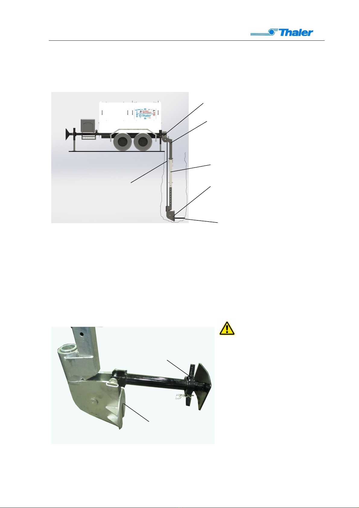
The majority of winch operations using the winch involve either a manhole or trench box
(excavation). The following setup will describe a typical underground cable laying situation.
2 A. Winch Placement and Manhole Selection
A pre-survey of the site conditions will help the operator determine which manhole to set the winch,
what position around the manhole to set the winch; and depth of manhole will determine the length of
the boom.
An ideal winch placement includes adequate space for cable and equipment staging, minimal
disruption to the surrounding area and a properly sized manhole in good condition (see Fig.).
In a pipe bursting application the receiving manhole or winch manhole selection is based on several
factors including the following.
1. CABLE STAGING
Adequate space is needed to safely and properly stage the fused length of cable laying.
Avoiding public inconvenience or disruption such as blocked driveways or business entrances may
require switching manhole choice.
2. OBSTACLES
Any obstacles adjacent to the selected manhole such as street lights, trees, damaged walls,
landscaping, etc. and ground conditions such as mud, water, decorative stone, peripheral utilities, etc.
will affect where and how the winch can be set up.
3. MANHOLE CONSTRUCTION OR CONDITION
Offset inverts and chimneys, damaged walls and loose bricks may make the manhole unusable.
NOTE: Cones, barricades, etc., should be placed around the winch in a traffic situation. A minimum
10-ft. (3 m) working radius around the winch is desired to prevent traffic problems.
Boom
Cable
Exit pit
Support leg

Jakob Thaler GmbH
25335 Elmshorn GERMANY
Stabilizing the Winch
The KE-SP 60100 GM has two rear jacks in addition to the front jack stand. This allows leveling
both laterally and side to side. In most situations, this is done after the winch boom is in position (if
required).
1. Turn the rear jack down.
2. Turn the front jack down to ensure proper stand of the winch.
Use proper lashing equipments as chains or
belts and connect them with the eyes of the
winch and a rigid point.
Rear Jack
Front Jack
Lashing points
Only for lifting the winch
Lashing eyes

Jakob Thaler GmbH
25335 Elmshorn GERMANY
Boom Assembly
Warning:
The assembled boom is too heavy for manual installation! The use of a backhoe is
recommended to avoid injury
Top section
Intermediate section
Swivel bottom section
Support leg
bolt
bolt
bolt
Jakob Thaler GmbH
25335 Elmshorn GERMANY
Boom Installation
Place the top section of the boom to the swivel pulley of the winch. Secure it with the appropriate
bolt. Dependent of required working depth use the intermediate sections. Fit them the top section.
Mount the swivel bottom section and adjust it to the required working depth.
Pull out the rope and insert the thimble of the rope through the swivel bottom section and guide the
rope over the pulley.
Note:
The face plate of the bottom section must placed against a rigid part in the pit or the support
leg must be mounted to the face plate and andjusted with the spindle to match a solid part!
When working with the
complete boom unit (maximum 16
ft.) it may be required to use
additional support legs at the
inter mediate sections! The
sections are fitted with
appropriate eys.
Swivel pulley
Top section
Intermediate section
Swivel bottom section
Winch rope
Winch rope
Face plate
Adjustable spindle

Jakob Thaler GmbH
25335 Elmshorn GERMANY
Boom Application
When using the top and the swivel bottom section only the minimum working depth is 4 ft. and the
Maximum working depth 6 ft.
With one intermediate section the maximum working depth is 9 ft. With two intermediate sections
the maximum working depth is 13 ft. and with three sections 16 ft.
The bottom part of the boom is depth-adjustable in 3.94 inches steps. The supporting leg is
adjustable from 22 inches up to 34 inches

Jakob Thaler GmbH
25335 Elmshorn GERMANY
Starting the Winch Before
Check to see if it is safe around the winch before starting.
Check low fuel indicator (only Diesel engines) when ignition
switch is on, if necessary fill with diesel fuel as required.
Check motor oil and hydraulic oil levels and fill as needed. (For
type of oils to be used check Technical Specifications.)
Make sure all covers and shields are closed and secured,
before start-up. (Except for winch controls cover.)
Make sure the dead man’s control is switched on.
Make sure the emergency-stop button is not pressed.
Caution: Do not run the winch in closed or poorly vented
areas.
Starting Procedure
Turn the winching lever to the neutral position
Set the engine throttle lever to a middle position.
Turn the ignition switch to the start position.
Do not start for longer than 20 sec. If winch did not start allow
starter to cool before attempting to start again.
Cold Starting Procedure
In cold weather the engine and hydraulic oil need a longer warm up time, allow at least 5-10 minutes
at half throttle before operating any functions.
NOTICE: Never use any spray starting additives, damage to the engine
could occur.
Winch Payout Procedure
With engine running using the throttle lever
increase engine speed to a 3/4 throttle.
Turn the winching lever completely into “pay-out”
position
Pull winch line out as needed.
Set the winching lever in 0 position
when the rope has been pulled out. Never
keep the capstan sheaves turning over a
longer period without pulling! Otherwise the
steel wire rope cause excessive wear to the
sheaves!

Jakob Thaler GmbH
25335 Elmshorn GERMANY
Winching In
After the rope has been pulled out to the
required length and the cable is connected
shift the lever carefully into “pull-in” position.
Observe winch’s movement. Stop winching
immediately if the winch is not proper
anchored!
During pull keep a balance between
generated pulling force and line speed. As
higher the reqired pulling force than lower
the line speed.
When pulling in the rope it must be sure that the rope is not pulled over sharp edges. Use
only swivel joints and tools which are declassified from winch’s manufacturer suitable for
use.
Make sure that no person enter the manhole during pull!
Stop winching
Shift the
winching lever in neutral position to stop
process.
Remove the cable from the rope’s thimble.
When pulling in the rope for transport make sure
that the thicker end is not pulled into the swivel
pulley to avoid damages to the layering arm and
measuring system!
For transport fix the end to a lashing eye with a
shackle.
Table of contents


