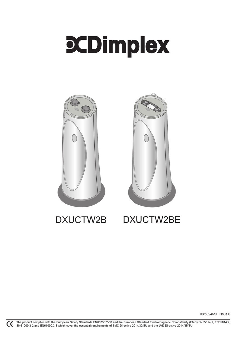
The Collection By Michael Miller Glimpse Mounting instructions

Glimpse, Glimpse Duplex R,
Glimpse Duplex L
& Glimpse Triplex
LOG EFFECT BALANCED FLUE ROO HEATER
Installation, aintenance & User Instructions
Hand these instructions to the user
odel No. DCHLSTRN, DCHLCRRN, DCHLLRN & DCHL3SRN are for use on Natural
Gas (G20) at a supply pressure of 20 mbar in G.B. / I.E.

CONTENTS
PAGE
Section 1 Information and requirements
1.0 Appliance information 3
1.1 Product dimensions - Glimpse model 4
1.2 Product dimensions - Glimpse “Duplex R” model 5
1.3 Product dimensions - Glimpse “Duplex L” model 6
1.4 Product dimensions - Glimpse “Triplex” model 7
1.5 Conditions of installation 8
1.6 Flue terminal position 9
Section 2 Installation of the fire
2.1 Unpacking the components 9
2.2 Specifying the flue system and associated components 10
2.3 Installation of the gas supply 11
2.4 Balanced flue system in horizontal configuration 12
2.5 Balanced flue system in vertical configuration 13
2.6 Balanced flue system in vertical configuration (flat roof) 13-14
2.7 Balanced flue system in vertical configuration (pitched roof) 14
2.8 Securing the combustion chamber - Glimpse model 15
2.9 Securing the combustion chamber - Glimpse “Duplex R” & “Duplex L” models 16
2.10 Securing the combustion chamber - Glimpse “Triplex” model 17
2.11 Assembling the false chimney breast - Glimpse model 18-21
2.12 Assembling the false chimney breast - Glimpse “Duplex R” & “Duplex L” models 22-25
2.13 Assembling the false chimney breast - Glimpse “Triplex” model 26-30
2.14 Removing / replacing the glass panels - all models 31-32
Section 3 Assembling the fuel-bed and commissioning
3.1 Assembling the log fuel-bed - Glimpse, Glimpse “Duplex R” & Glimpse “Triplex” models 33
3.2 Assembling the log fuel-bed - Glimpse “Duplex L” model 34
3.3 Assembling the pebble fuel-bed - all Glimpse models 35
3.4 Ceramic log set advice 36
3.5 Positioning the flue restrictor plates 36
3.6 Making the final gas connection & checking for gas tightness 36-37
3.7 Making the electrical connection 37
3.8 Lighting the appliance 37-40
3.9 Fitting the handset wall bracket & dimmer light bulbs 40
3.10 Instructing the user / product handover 40
Section 4 Servicing and maintenance / repair
4.1 Removing and replacing the burner assembly 41
4.2 Removing and replacing the burner controls plate assembly 41
4.3 Removing and replacing the gas control valve 41
4.4 Removing and replacing the control board / receiver unit 41
4.5 Removing and replacing the pilot assembly 42
4.6 Removing and replacing the main burner injector 42
4.7 Removing and replacing the power module 42
4.8 Removing and replacing the convection fan assembly 42
4.9 Removing and replacing a dimmer light bulb 43
4.10 Wiring diagram 44
4.11 Spare parts list 45
Section 5 User Instructions
5.1 Installation Information 46
5.2 About your new gas fire 46
5.3 Lighting the fire / user controls 47-50
5.4 Cleaning instructions 50
5.5 Removing / replacing the glass panels 51-52
5.6 Assembling the log fuel-bed - Glimpse, Glimpse “Duplex R” & Glimpse “Triplex” models 53
5.7 Assembling the log fuel-bed - Glimpse “Duplex L” model 54
5.8 Assembling the pebble fuel-bed - all Glimpse models 55
5.9 Ceramic log set advice 55
5.10 User replaceable spare parts list 56
2

SECTION 1
INFOR ATION AND REQUIRE ENTS
1.0 APPLIANCE INFOR ATION
GAS INFOR ATION
Main injector : (1 off) Stereomatic Pattern 4 – size 2.55mm
Pilot Type : Black Technigas - Polidoro G27.2
Max. Gross Heat Input : 9.8kW
Min. Gross Heat Input : 4.5kW
Gas Rate : 0.903 m3/hr (High)
0.415 m3/hr (Low)
Cold Pressure : (G20) 20.0+/-1.0 mbar (8.0 +/- 0.4 in w.g.)
Ignition : Via remote handset, integral to gas valve control system
Electrode Spark Gap : 4.0mm
NOx Level Class 5
Packed Weight Combustion Chamber 105kg
ELECTRICAL INFOR ATION - PLEASE NOTE THIS PRODUCT REQUIRES A AINS ELECTRICITY SUPPLY
Supply Voltage : 230V a.c.
Supply Frequency : 50Hz
Supply Fuse : 3 Amp to BS 1362
Electrical Supply Required 230v AC, 50Hz
IP Rating IPX0
APPLIANCE EFFICIENCY DECLARATION
The efficiency of this appliance has been measured as specified in BS EN 613 : 2001 on a CII flue systen and the result
obtained is up to 69%. The gross calorific value of the fuel has been used for this efficiency calculation. The test data from
which it has been calculated has been certified by BSI. The efficiency value may be used in the U Government’s Standard
Assessment Procedure (SAP) for energy rating of dwellings.
3

1.1 PRODUCT DI ENSIONS - GLI PSE ODEL
Fig. 1 FRONT VIEW
Fig. 2 TOP VIEW
4

1.2 PRODUCT DI ENSIONS - GLI PSE “DUPLEX R” ODEL
Fig. 3 FRONT VIEW
Fig. 4 TOP VIEW
5

1.3 PRODUCT DI ENSIONS - GLI PSE “DUPLEX L” ODEL
Fig. 5 FRONT VIEW
Fig. 6 TOP VIEW
6

1.4 PRODUCT DI ENSIONS - GLI PSE “TRIPLEX” ODEL
Fig. 7 FRONT VIEW
Fig. 8 TOP VIEW
7

INSTALLATION REQUIRE ENTS
1.5 CONDITIONS OF INSTALLATION
It is the law that all gas appliances are installed only by a GAS SAFE Registered Installer, in accordance with these
installation instructions and the Gas Safety (Installation and Use) Regulations 1998 as amended. Failure to install
appliances correctly could lead to prosecution. It is in your own interest and that of safety to comply with the law.
The installation must also be in accordance with all relevant parts of the Local and National Building Regulations where
appropriate, the Building Regulations (Scotland Consolidation) issued by the Scottish Development Department, and all a
pplicable requirements of the following British Standard Code of Practice.
1. B.S. 5871 Part 1 Installation of Gas Fires
2. B.S. 6891 Installation of Gas Pipework
3. B.S. 5440 Parts 1 & 2 Installation of Flues and Ventilation
4. I.S 813 : 1996 Domestic Gas Installation, issued by the National Standards Authority of Ireland.
1.6 FLUE TER INAL POSITION
The minimum acceptable dimensions from the flue terminal to obstructions and ventilation openings are shown
below and listed in the table. It is important that the position of the flue allows the free passage of air across it at
all times. The minimum acceptable space from the flue terminal to obstructions and ventilation openings are s
pecified below in figure 9.
Fig. 9
DI ENSION TER INAL POSITION INI U DI ENSION
A Directly below an opening, air brick, 300mm (12in)
opening window
B Above an opening, air brick, 300mm (12in)
opening window
C Horizontally to an opening, air brick,
opening window etc.
D Below gutters, soil pipes or drain pipes 300mm (12in)
E Below eaves 300mm (12in)
F Below balconies or car port roof 600mm (12in)
G From a vertical drain pipe or soil pipe 300mm (12in)
H From an internal or external corner 600mm (24in)
I Above ground roof or balcony level 300mm (12in)
J From a surface facing the terminal 600mm (24in)
K From a terminal facing the terminal 600mm (24in)
L From an opening in the car port 1200m (48in)
Vertically from a terminal on the same wall 1500mm(59in)
N Horizontally from a terminal on the 300mm (12in)
same Wall
O NOT APPLICABLE N/A
P NOT APPLICABLE N/A
Q NOT APPLICABLE N/A
8

SECTION 2
INSTALLATION OF FIRE
2.1 UNPACKING THE CO PONENTS
Remove the loose item packaging carefully from the pack. Check the contents as listed :-
Packing Check List - Product & Flue Kit
Pack 1 of 3 - Combustion Chamber Pack
1 off Combustion chamber & glass assembly
1 off Boxed ceramic fuel-bed set (packed inside combustion chamber)
1 off Installation / user instruction manual
2 off Convection air grills (Glimpse or Glimpse “Duplex L” or “Duplex R” models only)
3 off Convection air grills (Triplex models only)
1 off Loose items pack – containing :- 3 off AAA 1.5v batteries, 2 off combustion chamber securing
brackets, remote handset, 1 off handset wall brkt (inc. fixings),
1 off glass removal tool, 2 off G9 Halogen bulbs (Duplex “L” &
Duplex “R” models) 4 off off G9 Halogen bulbs (Glimpse & Triplex models
only)
Pack 2 of 3 - Horizontal Balanced Flue System Pack
1 off Adaptor 1 off 0.5m length of flue 1 off Terminal guard
1 off 90 degree elbow 1 off Horizontal wall terminal 2 off Locking bands
1 off Protection band
or
Pack 2 of 3 - Vertical Flue Kit
1 off Adaptor 1 off Vertical terminal
In addition, all flue lengths, roof flashing, clamps and accessories as required by the individual flue system design should be
purchased as required from the manufacturer, if you require to purchase any additional flue components, please contact the
U distributor for Metaloterm products, contact details as below :-
H Docherty Ltd
Unit 15 &16 Colthrop Business Park
Colthrop Lane
Thatcham
Berkshire
RG19 4NB
Tel : 0845 6031715 Fax : 01635 201737
Packing Check List - False Chimey Assembly Kits
Pack 3 of 3 - Glimpse “Triplex” Kit or Pack 3 of 3 - Glimpse “Duplex L or R” Kit
10 off 3 metre lengths of “C” section frame 7 off 3 metre lengths of “C” section frame
4 off Horizontal channel “A” 2 off Horizontal channel “A”
4 off Horizontal channel “B” 4 off Horizontal channel “B”
4 off Floor / ceiling channel “A” 2 off Floor / ceiling channel “A”
4 off Floor / ceiling channel “B” 2 off Floor / ceiling channel “C”
1 off Front support channel 2 off Horizontal channel “C”
2 off Tie bar bracket 1 off Front support channel
2 off Lengths of M8 threaded bar - 1400mm long 1 off Tie bar bracket
8 off M8 hex nuts (black) 2 off Lengths of M8 threaded bar - 1400mm long
4 off M8 hex nuts (black)
or Pack 3 of 3 - Glimpse “See Thru” Kit
12 off 3 metre lengths of “C” section frame
4 off Horizontal channel “D”
8 off Horizontal channel “E”
2 off Floor / ceiling channel “D”
2 off Floor / ceiling channel “B”
2 off Horizontal channel “C”
9
DO NOT UNDER ANY CIRCU STANCES INSTALL THIS APPLIANCE IF ANY OF THE GLASS
PANELS ARE BROKEN OR NOT SECURELY FIXED TO THE CO BUSTION CHA BER.

2.2 SPECIFYING THE FLUE SYSTE & ASSOCIATED CO PONENTS
This product comes with the option of 2 methods of flueing :-
Decide upon the method of flue that is most suitable for the property in which you are installing the product, from the
following options :-
2.2.1 Balanced Flue in Horizontal Configuration
This flueing method uses a 0.5 metre vertical pipe starter pipe section, then utilises a 90 degree elbow and a terminal
section to provide a horizontal pipe from 324mm (minimum) up to 469mm (maximum). Additional flue duct can then be
purchased to allow installation up to a maximum wall thickness of 1395mm. The flue can be installed to terminate directly
out the wall behind the appliance or at the L/H side or R/H side by rotating the elbow section. If the terminal is fitted below
2m from ground level, a terminal guard must be fitted in England & Wales. BFM Europe supply a suitable guard in the
Horizontal Flue it. See section 2.4
2.2.2 Balanced Flue in Vertical Configuration
This flueing method utilses a rigid interlocking balanced flue duct to enable a vertical balanced flue system to be used. All
components required are supplied within the flue kit with the exception of the lengths of co-axial pipe and storm collars
which are dependent upon the individual installation. This method is most suited when a false chimney breast is being
constructed due to no chimney / insufficient depth and an outside wall is not available. See section 2.5
2.2.3 Flue Outlet Position
For vertical balanced flue configurations a choice of 2 outlet positions for the flue ducting are provided on the top of the
combustion chamber as shown below in figure 10. Dependent upon the flue outlet chosen and flue
configuration utilised a differing flue restrictor position will be required, see section 3.5 for further details.
THE CENTRAL FLUE OUTLET POSITION UST ONLY BE USED FOR VERTICAL FLUE CONFIGURATIONS. FOR
HORIZONTAL FLUE CONFIGURATIONS USE THE END FLUE OUTLET ON TOP OF THE CO BUSTION CHA BER.
Fig. 10
10
Central flue outlet (for vertical flue use only)
End flue outlet (for vertical or horizontal flue)
Remove cardboard packing fitment from here
(retains explosion relief flaps in position)

2.2.4 Leg Height Adjustment
Adjust the height of the legs to suit the installation height for the product that you wish to achieve to obtain the required
aesthetic look the customer wants. There are various adjustment positions for the legs on the combustion chamber as
shown below in figure 11. Remove securing screws / bolts, adjust leg height and replace screws / bolts as required.
Fig. 11
To enable fine adjustment of the product when in its final position, there is adjustment available via the rubber feet as shown
on figure 11 above, the feet can be adjusted using a 1/2” open ended spanner.
2.3 INSTALLATION OF THE GAS SUPPLY
2.3.1 Before installing the combustion chamber, decide from which side or if a rear connection to the gas supply is
required. Plan the pipe run to enter from below the combustion chamber from the left, right or rear and connect
to the inlet elbow.
2.3.2 Ensure if the gas supply is routed through any cavity brickwork that the pipe is sleeved and sealed with a suitable
flexible, non setting compound.
Note : Before breaking into the gas supply a gas tightness test should be carried out to establish that the
existing pipework is sound.
Note : On Duplex “L”, Duplex “R” and Triplex models please ensure that the transit brackets are removed from
the product before continuing with the installation.
11

2.4 BALANCED FLUE IN HORIZONTAL CONFIGURATION
2.4.1 Horizontal balanced flue configuration and components identified as shown below in figure 12
Fig. 12
2.4.2 Mark the position of the centre of the flue on the inner wall, taking into account the adjustment available for the
height via the adjustable feet. (See figure 4 above for position).
2.4.3 Cut hole for outer flue pipe. There are two possible methods to achieve this, either core drill or via hammer and
chisel.
2.4.4 To core drill, proceed as follows :-
2.4.5 Drill a pilot hole through the wall, in position as specified in figure 12 above.
2.4.6 Using a 6” core drill, drill the flue hole.
2.4.7 To Hammer and chisel, proceed as follows :-
2.4.8 Mark the position of the centre of the flue pipe as specified in figure 12 above.
2.4.9 Mark the position of the hole around this point.
2.4.10 Chisel out the area as marked on the wall.
2.4.11 We then recommend that a cardboard cylinder is placed around the flue pipe and inserted in the chiselled out
hole whilst making good. A wall plate is provided on the flue duct to seal the terminal around the
flue pipe opening and make good. Please ensure all joints are taped with suitable high temperature tape when
assembling the flue pipe sections together.
NOTE :- If the appliance is to be installed into a building under construction, it is recommended that a
non-corrosive metal tube of 6” diameter be inserted into the position of the hole as specified above in
figure 4, ensure the terminal guard that is supplied is fitted if the flue outlet position requires it to be.
PLEASE NOTE : THE FLUE TER INAL SHOULD BE FITTED WITH THE WELDED
JOIN LINE AT THE BOTTO , FACING THE GROUND.
12
IMPORTANT NOTE
ENSURE FOR HORIZONTAL FLUE CONFIGURATIONS THE
FLUE DUCT IS ATTACHED TO THE END OUTLET AS SHO N
ON THIS DIAGRAM, DO NOT USE THE CENTRAL OUTLET

2.5 BALANCED FLUE IN VERTICAL CONFIGURATION
2.5.1 Vertical flue configuration and components identified as shown below in figure 13.
Fig. 13
2.6 BALANCED FLUE IN VERTICAL CONFIGURATION (FLAT ROOF)
2.6.1 Determine the position of the flue run within the property and the termination position is correct in accordance
with BS 5440. Ensure that clearances to combustible surfaces (50mm minimum) are sufficient where the flue run
may come within close contact of joists etc.
2.6.2 For a flat roof installation the following components will need to be ordered from Metaloterm :-
USMPG13 Mounting plate US B13 Locking band
US100-13/50-13/25-13 Concentic flue - quantity required USDP13 Flat roof flashing
dependent upon flue height required
USSR13 Storm collar
2.6.3 To install the flue system therefore, make hole in roof, install the mounting plate (USMPG13) underneath the roof
and secure with screws. (See figure 14 overpage)
2.6.4 Place a locking band (US B13) in the mounting plate (USMPG13). Put the concentric flue US100-13/50-13/25-
13 through the mounting plate and locking band until it protrudes by 400mm min, 1000mm max through the roof.
Fix the flat roof flashing (USDP13) over the flue and fix it to the flat roof. See figure 14 overpage. Please ensure
all joints are taped with suitable high temperature tape when assembling the flue pipe sections together.
2.6.5 Seal the opening between the flue and flashing with silicone rubber and a storm collar (USSR13). See figure 14
overpage.
2.6.6 Install the terminal (contained within the terminal kit requested at point of order from BFM Europe Ltd.) with a
locking band and fix with 3 nuts.
2.6.7 Finish the roof covering over the flashing and weatherproof.
Combustion
Chamber
Vertical Terminal
Locking Bands
Adaptor
inimum Flue Height = 3 metres
aximum Flue Height = 10 metres
For details of weather proofing
options at point of exit, please
see sections 2.5 for a flat roof or
2.6 for a pitched roof
13

Fig. 14
2.7 BALANCED FLUE IN VERTICAL CONFIGURATION (PITCHED ROOF)
2.7.1 Determine the position of the flue run within the property and the termination position is correct in accordance
with BS 5440-1. Ensure that clearances to combustible surfaces (50mm minimum) are sufficient where the flue
run may come within close contact of joists etc.
2.7.2 For a pitched roof installation the following components will need to be ordered from Metaloterm :-
USCP13 Cover plates (pair)
US B13 Locking band
US100-13/50-13/25-13 Concentic flue - quantity required dependent upon flue height required
USDH13 Slope roof flashing or USLS13 Lead slope roof flashing
USSR13 Storm collar
USDQ13 Roof support
2.7.3 To install the flue system therefore, make hole in roof, install the pair of cover plates (USCP13) underneath the
roof, put the concentric flue US100-13/50-13/25-13 through the mounting plate and locking band until it protrudes
by 400mm min, 1000mm max through the roof. Centre the flue and secure with the roof support (USDQ13) and
screws. (See figure 15 below) Please ensure all joints are taped with suitable high temperature tape when
assembling the flue pipe sections together.
2.7.4 Put the slope roof flashing USDH13 (or in the case of a tiled roof the lead flashing USLS13) over the flue and
make a weather proof finish. Seal the opening flue and flashing with the silicone rubber and the
storm collar (USSR13).
2.7.5 Install the terminal (contained within the terminal kit requested at point of order from BFM Europe Ltd.) with a
locking band and fix with 3 nuts.
2.7.6 Finish the roof covering over the flashing and weatherproof.
Fig. 15
Terminal
Flashing (USDP13)
Concentric flue ounting plate
(US PG13)
Storm collar
(USSR13)
Concentric Flue
Protrudes 400mm
minimum, 1000mm
maximum through
Terminal
Flashing (USDP13)
Concentric flue
ounting plate
(US PG13)
Storm collar
(USSR13)
Concentric Flue
Protrudes 400mm
minimum, 1000mm
maximum through
roof
14

2.8 SECURING THE CO BUSTION CHA BER - GLI PSE ODELS
2.8.1 The product must be secured to the false chimney breast structure, using the brackets supplied in the loose items
kit, as shown below in figure 16. Use fixings suitable for the structure of the false chimney breast
Fig. 16
NOTE : The dimensions as stated in figure 16 above are dimensions specified for use with the optional false
chimney breast construction kits as supplied by BF Europe. Please be aware that fixing points for
retailer designed false chimney breast constructions may differ from those stated in figure 16 above.
15
Securing brackets

2.9 SECURING THE CO BUSTION CHA BER - DUPLEX “R” & DUPLEX “L” ODELS
2.9.1 The product must be secured to the fabric of the building, using the brackets supplied in the loose items
kit, as shown below in figure 17. Use fixings suitable for the fabric of the building the product is being secured to.
Fig. 17
NOTE : The dimensions as stated in figure 17 above are dimensions specified for use with the optional false
chimney breast construction kits as supplied by BF Europe. Please be aware that fixing points for
retailer designed false chimney breast constructions may differ from those stated in figure 17 above.
Securing brackets
16

2.10 SECURING THE CO BUSTION CHA BER - TRIPLEX ODELS
2.10.1 The product must be secured to the fabric of the building, using the brackets supplied in the loose items
kit, as shown below in figure 18. Use fixings suitable for the fabric of the building the product is being secured to.
Fig. 18
NOTE : The dimensions as stated in figure 18 above are dimensions specified for use with the optional false
chimney breast construction kits as supplied by BF Europe. Please be aware that fixing points for
retailer designed false chimney breast constructions may differ from those stated in figure 18 above.
Securing brackets
17

2.11 CONSTRUCTION OF THE FALSE CHI NEY BREAST - “GLI PSE” ODELS
2.11.1 To assist in the construction of a false chimney breast a series of kits are available to order from BFM Europe.
Whilst it is not mandatory to use these kits the manufacturer does recommend they are used as they have been
specifically designed to suit the product.
2.11.2 Firstly check the kit contains the components as shown below in figure 19, then follow the instructions as detailed
to fit the false chimney breast.
2.11.3 Ensure provision for the gas and electricity connections to the product have been made (section 3.6 & 3.7) before
making good the false chimney breast.
Fig. 19
PLEASE NOTE : For the external faces of the studwork a non combustible board such as “Promat Supalux”
should be used in a double 6mm thickness, giving an overall thickness of 12mm
“Promat Supalux” board is available from CCF anchester, Tel : (0161) 877 4088
18

2.11.4 Proceed as detailed below in figure 20 & 21
Fig. 20
Fig. 21
19

2.11.5 Proceed as detailed below in figure 22 & 23
Fig. 22
Fig. 23
20
STAGE 4
1.) FIT THE RE AINING 4 OFF ITE
A THAT WERE CUT TO LENGTH IN
STAGE 2 ON EITHER SIDE OF THE
APERTURE, USE A 12 SPACER
(I.E. 2 X 6 BOARD) TO PROVIDE
THE GAP AS SHOWN IN THE
DIAGRA .
2.) FIT 4 OFF ITE D TO CO -
PLETE THE APERTURE, AGAIN USE
THE 2X6 BOARD TO AINTAIN
THECORRECT GAP.
3.) CUT 2 OFF LENGTHS OF ITE A
TO PROVIDE THE TOP AND
BOTTO SECTIONS AND FIX IN
PLACE AS SHOWN
4.) FIT 8 OFF ITE
E INTO POSITION
AS SHOWN,
PLEASE NOTE
THESE ARE
STAGGERED TO
PROVIDE
SUPPORT BEHIND
JOINT IF
CLADDING IS
FITTED AS
SUGGESTED IN
STAGE 5 OTHER-
WISE FIT TO ALIGN
WITH JOINT AS
REQUIRED.
5.) FIT ITE F AS
REQUIRED TO
ALIGN WITH
JOINTS IN BOARD
6.) FIT WALL
BRACKETS TO
INNER FACE OF
FRA E AS SHOWN
This manual suits for next models
3
Table of contents


