The Great American Train Company Pioneer Mogul 2-6-0 User manual

THE
GREAT AMERICAN
TRAIN COMPANY
SKU 510820-060208
Pioneer Mogul (2-6-0)
Steam Profile Locomotive
Owner’s Manual
IMPORTANT
You must carefully read this Manual before operating The Great American Train Company
Mogul (2-6-0) Steam Profile Locomotive to avoid personal injury or property damage.


Contents
Introduction.........................................................................................................................................2
General Safety Information................................................................................................................2
Locomotive & Tender Assembly.......................................................................................................5
Control Panel Functions....................................................................................................................6
Filling The Smoke Reservoir .............................................................................................................8
Operation Safety Rules ......................................................................................................................9
Operation...........................................................................................................................................10
Troubleshooting ...............................................................................................................................12
Towing...............................................................................................................................................13
Lubrication & Chain Adjustment.....................................................................................................13
Storage & Cleaning...........................................................................................................................16
Fuses .................................................................................................................................................17
Attaching a Riding Car.....................................................................................................................18
Specifications ...................................................................................................................................19
Replacement Parts ...........................................................................................................................19

Introduction
General Safety Information
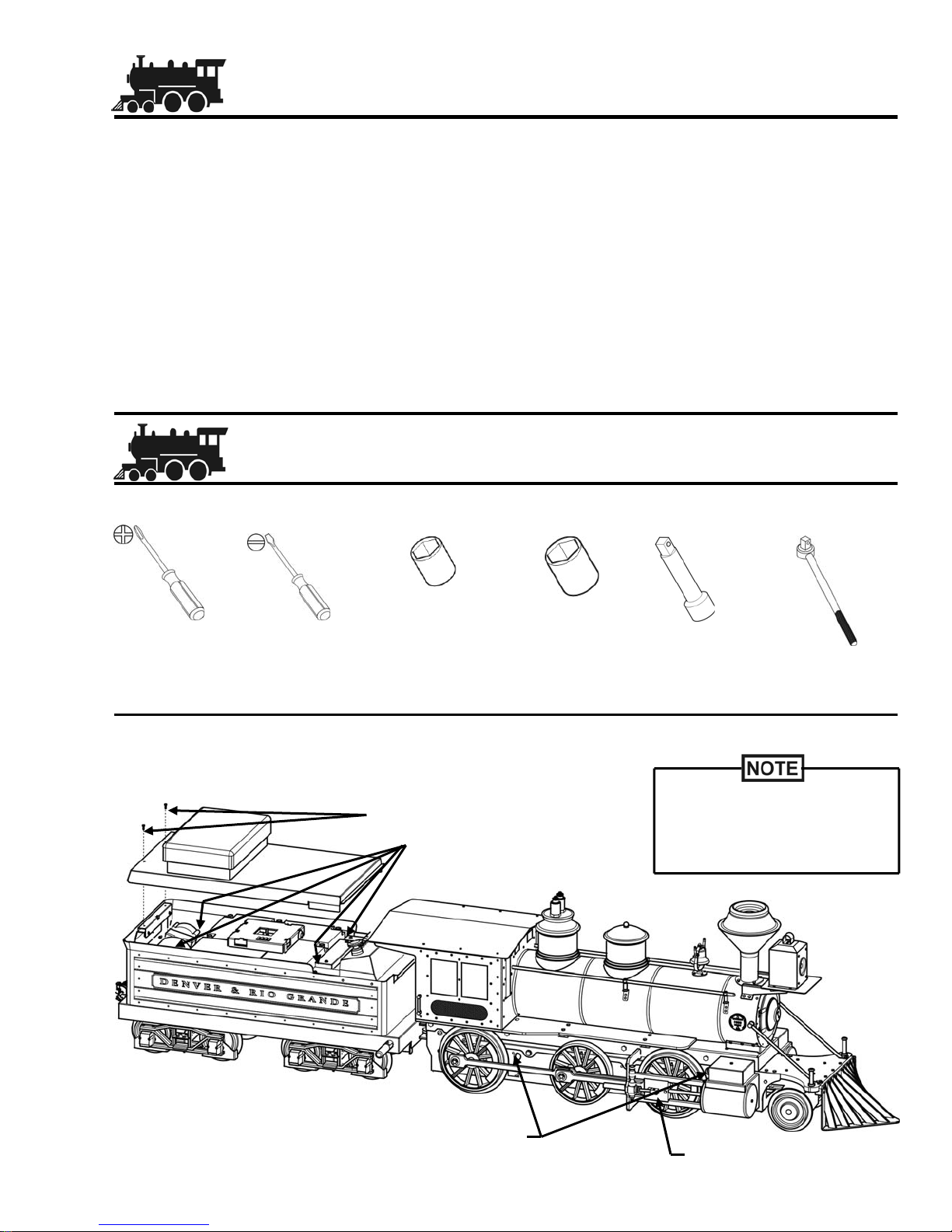
Notes are used to notify of installation,
operation, or maintenance information that is
important but not safety related.
Caution without the Safety Alert Symbol is used
to indicate the presence of a hazard, which if
ignored may result in property damage.
Caution with the Safety Alert Symbol is used to
indicate the presence of a hazard, which if
ignored may result in property damage and or
minor personal injury.
Warning denotes that a potential hazard exists
and indicates procedures that must be followed
exactly to either eliminate or reduce the hazard,
and to avoid serious personal injury, or prevent
future safety problems with the product.
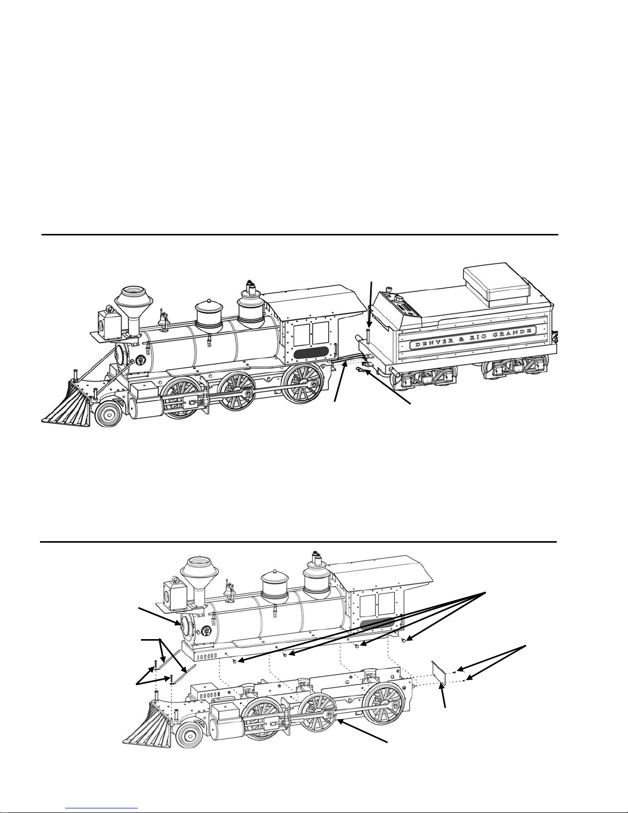
Congratulations on the purchase of your Great American Train Company (GATC), Mogul (2-6-0)
Steam Profile Locomotive. This model’s authentic styling is based upon the famous Baldwin Mogul
built by the Baldwin Locomotive Works of Philadelphia, Pennsylvania, U.S.A. during the late 1800s
and early 1900s. Baldwin Moguls were used extensively in the narrow-gauge railroads of the Old West
and particularly on the Denver and Rio Grande.
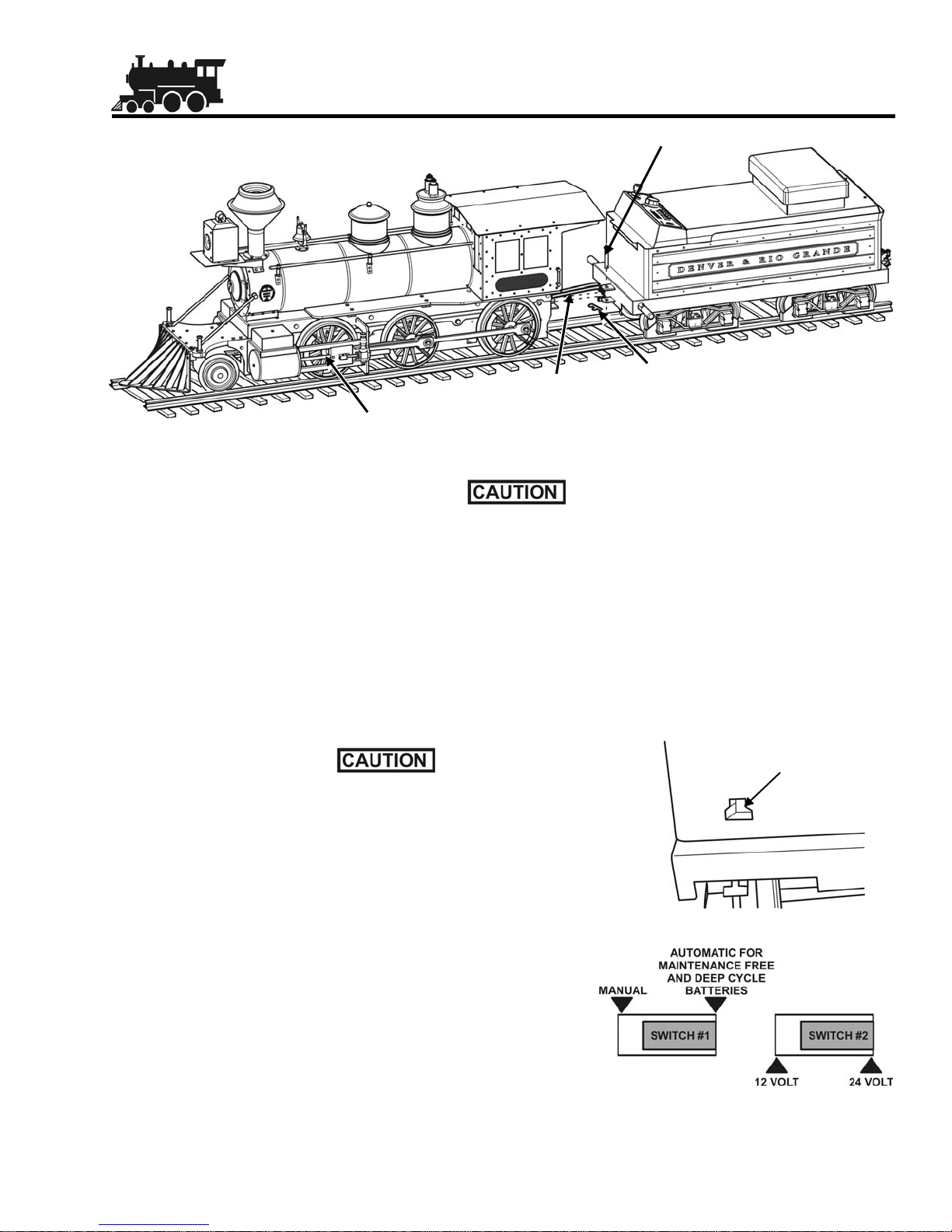
All Great American Train Company Locomotives are 24 VDC battery powered for safe, efficient and
reliable operation. Rated pulling power is awesome with its 1kW total motor power – about 1600 lbs.
of load on a 3% grade.
If you have any questions concerning the assembly and use, or if you feel your product is not working
properly, contact The Great American Train Company at 763-476-5140, or visit our website at
www.greatamericantrain.com.
Read these Instructions carefully, making full use of all explanations and instructions. The “Know
How” of trouble free operation of your railroad depends on the degree of your understanding of the
system and willingness to keep all components in proper operating condition. Pay particular attention
to all NOTES, CAUTIONS, and WARNINGS to avoid the risk of personal injury or property damage. It
is important to understand that these NOTES, CAUTIONS, and WARNINGS are not exhaustive. The
Great American Train Company cannot possibly know or evaluate all conceivable methods in which
procedures may be performed, or the possible hazardous consequences of each method.
Accordingly, anyone who uses a procedure that is not recommended by GATC assumes the risk of
personal injury or property damage.
When unpacking your product, inspect each crate to ensure that no damage occurred during shipping.
If damage has occurred during shipping, contact the shipper immediately. Remove all components
from the shipping crates and inspect them. If any components are missing or damaged, contact The
Great American Train Company immediately at 763-476-5140. Do not use or assemble the product if
any components are damaged or missing. Do not use substitute components not manufactured by
The Great American Train Company.
2

The GATC Steam Profile Locomotive weighs 180 lbs. (82kg) and the Tender, including batteries,
weighs 215 lbs. (98kg). Never try to lift the Locomotive or the Tender without assistance. Trying to lift
either the Locomotive or Tender may result in personal injury.
Use only GATC Smoke and Steam Fluid (SKU-42650). DO NOT USE FLAMMABLE LIQUIDS.
Use of other products will void warranty, plus result in damage to the Locomotive and possible
personal injury.
The GATC Steam Profile Locomotive is not a toy. Children under the age of sixteen (16) should
not be allowed to operate the Locomotive without adult supervision. GATC will not be
responsible for any damage or injury incurred through misuse or negligent operation of any
GATC product.
General Battery Safety
Working in the vicinity of a lead-acid battery is dangerous. Batteries generate explosive gases during
normal battery operation. For this reason, it is of utmost importance that before using the battery
charger, read this manual and the manual provided with the Battery Charger, following the instructions
exactly.
Do not use battery charger for charging dry-cell batteries that are commonly used with home
appliances. These batteries may burst and cause injury to persons and damage to property.
Use only attachments recommended or sold by manufacturer. Use of non-recommended
attachments may result in fire, electric shock, or injury.
When disconnecting the battery charger, pull by the plug not by the cord. Pulling on the cord
may cause damage to cord or plug.
Locate the battery charger power cord so it cannot be stepped on, tripped over, or subjected to
damage or stress.
Do not operate the battery charger with damaged cord or plug. Have cord replaced
immediately.
Do not operate the battery charger if it has received a sharp blow, been dropped, or otherwise
damaged in any way. Take it to a qualified professional for inspection and repair.
To reduce risk of electric shock, unplug the battery charger from outlet before attempting any
maintenance or cleaning.
Always charge batteries in a well ventilated area.
Risk of explosive gas. Locate the battery charger as far away from battery as DC charger
cables permit. Do not expose the battery charger to rain or snow.
Never charge a frozen battery. If battery fluid (electrolyte) is frozen, bring into a warm area to
thaw before charging.
3

4
General Safety Rules
To lift the Locomotive or the Tender requires four persons. Lift only at the locations indicated
in Figure 1. It is recommended that you wear leather gloves while lifting since there are several
sharp corners. Failure to wear leather gloves may result in cuts and increase the possibility of
dropping the Locomotive, potentially causing damage and injury.
Do not attempt to rotate the wheels of the Locomotive or Tender by hand, your fingers or hand
may get caught in the moving parts resulting in personal injury.
There are a number of sharp parts and corners on the Locomotive and Tender. Be careful when
performing maintenance since these parts can result in injury due to your hands coming in
contact with them.
Alterations to or modifications of the Locomotive or Tender are dangerous. Alteration or
modification can result in parts having inadequate strength, leading to the risk of accidents
resulting in serious, or in extreme cases, even fatal injury.
Select a secure, solid location for storage of your Locomotive. The Locomotive and Tender
together weigh almost 400 lbs. (182 kg). Storing them in an unstable location may result in the
Locomotive and/or Tender falling, resulting in possible injury. The height at which the
Locomotive and Tender are stored should not exceed 12 in. (30.5 cm) from the floor.
Running the Locomotive on any surface other than properly installed railroad track will
damage the wheels and may cause an accident.
When operating the Locomotive, do not exceed a speed of 3 mph (4.8 km/h). Traveling at a
speed above this may cause an accident or injury.
When operating the Locomotive, stop immediately when there are people present within 3 feet
(0.9 meters) to the left and/or the right of the track, or within 12 feet (3.7 meters) in front of the
train. Inform people in the area either verbally or with the train whistle that the Locomotive is
passing by. Collision or contact with people while the train is in motion may result in serious
injury or death.
Keep fingers clear of the Couplers while they are coming together. Failure to do so may result
in pinched fingers and personal injury.
Figure 1

Cotter
Pin
Clevis
Pin
Locomotive & Tender Assembly
Locomotive and Tender Assembly
Do not move the train onto or off of the track without first disconnecting the cables at the
Electrical Connectors and the Clevis Pin between the Locomotive and the Tender. Failure to
do so will result in damage to cables and Clevis Pin.
1. Place the Locomotive and Tender on the track.
2. Insert the three Electrical Connectors from the Locomotive into the three receptacles located on
the Tender (See Figure 2).
3. Insert the Clevis Pin to secure the Locomotive to the Tender; then, insert the Cotter Pin into the
hole in the Clevis Pin (See Figure 2).
Figure 2
Electrical
Connectors
The Batteries have been partially charged at the factory. To fully
charge the Batteries, plug the Connector from the Battery Charger
into the Charger Receptacle located on the back of the Tender.
(See Figure 3). When charging the Batteries observe all Safety
Notices and Instructions provided in the Battery Charger
Instructions provided with the Battery Charger.
Figure 3
Charger
Receptacle
Figure 4
Prior to charging, verify that the Charger Switch #1 is set to
Automatic for Maintenance Free and Deep Cycle Batteries
and Switch #2 is set to 24 volts (See Figure 4).
When charging the batteries, first plug the charger into the
Tender; then, plug the battery charger into the wall electrical
outlet.
After the charge is complete, unplug the battery charger power
cord from the wall electrical outlet; then, unplug the battery
charger from the Tender.
Crosshead
Assembly
5

LCD Display Readouts
LCD Error / Warnings Required Action
BATTERY EXPIRED Charge batteries.
BATTERY VOLTAGE LOW Battery charge is getting low. Charge batteries.
ENGINE MOTOR HOT Motor temperature is past the maximum allowed
temperature. Stop and let the motors cool.
ENGINE MOTOR GETTING HOT Motor temperature is past warning level
temperature. Reduce speed and/or load.
Control Panel Functions
Figure 5
Switches
1. Menu Button: +/-
2. Select: +/-
3. Whistle: On “Momentary” /Off
4. Bell: On/Off
5. Smoke: On/Off/Idle
6. Light: On/Off
Speed Control
1. Reverse / Neutral / Forward
2. LED: Indicates Speed Control Position.
LCD Display
Two line, sixteen character display.
Menu Items
1. Sound Volume: 0 - 100 %
2. Bass Volume: 0 - 16 %
3. Lamp Brightness: 0 - 100 %
4. Whistle Volume
5. System Setup Menu
(Goes to Sub-Menus if selected)
Sub-Menu Items
1. Language Select: Toggles through
languages.
2. Set Max. Forward Speed: 1.0 - 3.0 mph
3. Set Max. Reverse Speed: 1.0 - 3.0 mph
4. Set Max. allowed volume level: 0 - 100%
5. English / Metric Select
6. Idle Smoke Level: 0 - 100 %
7. Running Smoke Level: 0 - 100 %
8. LCD Back-Light Level: 0 - 100 %
9. LCD Contrast Level: 0 - 100 %
10. Information Display: RTD Calibrations
11. POT ZERO Calibration:
Factory set calibration. Contact Technical
Support at 763-476-5140, or send an email
assistance is required.
12. Set Battery Voltage Calibration:
Factory set calibration. Contact Technical
Support at 763-476-5140, or send an email
assistance is required.
13. Set LCD brightness: 0 - 16
6

LCD Error / Warnings Required Action
ENGINE MOTOR ERROR An Engine Motor is not detected when running.
Check wiring to motors.
ENGINE MOTOR OVERLOAD Motor current has exceeded recommended value.
Check for causes of overload. (Excessive grade/
load etc.)
ENGINE NOT CONNECTED Check connections between Locomotive and
Tender.
ENGINE MOTOR TMP SENSOR ERROR Motor Temperature Sensor not connected.
Check wiring to sensor.
FRONT PANEL FIRMWARE ERROR Firmware checksum not valid. Contact GATC.
SEAT SWITCH NOT ACTIVE Operator must be sitting on Tender Seat.
SMOKE TEMP SENSOR ERROR Smoker Temperature Sensor is not connected.
Check wiring to Smoke Sensor.
SOUNDS NOT LOADED Sound Board not initialized. Contact GATC.
SPEED SENSOR NOT CONNECTED Speed Sensor is not connected. Check wiring for
Speed Sensor.
TENDER MOTOR ERROR A Tender Motor is not detected when running.
Check wiring to motors.
TENDER MOTOR GETTING HOT Tender Motor temperature is past warning level
temperature. Reduce speed and/or load.
TENDER MOTOR HOT Tender Motor temperature is over maximum
allowed temperature. Stop and let the motors cool.
TENDER MOTOR OVERLOAD Tender Motor current has exceeded recommended
value. Check for causes of overload. (Excessive
grade/load etc.)
TENDER MOTOR TMP SENSOR ERROR Tender Motor Temperature Sensor not connected.
Check wiring to sensor.
To contact GATC’s Technical Support, please call 763-476-5140, or send an email to:
7

Filling the Smoke Reservoir
1. Remove the Acorn Nut from the Sand Dome (See Figure 6).
2. Remove the Sand Dome Top (See Figure 7).
3. Remove the Sand Dome Shell (See Figure 8).
4. Remove the Sand Dome Base (See Figure 9).
5. Fill the Smoke Reservoir to the bottom of the Plastic Tube (See Figure 10).
Do not over fill the Smoke Reservoir. Excess Smoke and Steam Fluid may spill out of the
Smoke Reservoir resulting in damage to other components. Only fill the Smoke Reservoir to
the bottom of the Plastic Tube (See Figure 10).
6. Reverse Steps 4 through 1after filling the Smoke Reservoir.
Figure 8
Figure 10Figure 9
Figure 7Figure 6
Use only GATC Smoke and Steam Fluid (SKU-42650). DO NOT USE FLAMMABLE LIQUIDS.
Use of other products will void warranty, plus result in damage to the Locomotive and possible
personal injury.
Acorn
Nut
Sand Dome
Top Sand Dome
Shell
Sand Dome
Base
Fill to bottom
of Plastic
Tube
8

Operation Safety Rules
9
Please follow these important safety rules when you or others are operating the GATC Mogul
(2-6-0) Steam Profile Locomotive. The Great American Train Company cannot foresee all
situations that may arise; therefore, these rules are meant only as a general guideline to safe
operation.
• All passengers in GATC riding cars who are between the ages of two (2) and fifteen (15) must sit
in the lower seats and must wear seatbelts. All GATC riding cars come equipped with seatbelts. If
you are using a car from a source other that GATC, you assume the risk that serious personal
injury may occur.
• Passengers must remain seated at all times and not shake or tilt the railcars.
• Hands and feet must remain in or on the Locomotive and/or railcars at all times.
• No scuffling, horseplay, grabbing at objects, or throwing of objects from the train.
• Passenger weight must be evenly distributed among multiple riding cars as well as within each
individual car. Never load a riding car with passenger weight to the outside of the car.
• Pregnant women, obese persons, recent surgery patients, or those with balance difficulty are
strongly advised not to ride the train.
• Operate the train at a safe speed not greater than three (3) mph. Trains carrying children, elderly
or disabled persons should travel at speeds slower than normal. Slow down on curves and when
passing through switches and grade crossings.
• Children under the age of two (2) should not ride the train. Children between the ages of two (2)
and fifteen (15) should sit in front of a responsible adult.
• Make sure the track is clear of any persons or obstructions in front of or in back of the train.
• Make sure the train is fully stopped and the parking brake is engaged before loading or unloading
passengers, and load or unload passengers at the flattest section of track possible. Passengers
must never jump off the train while it is moving.
• Check that the batteries are sufficiently charged.
• Monitor and appropriately respond to error messages on the LCD screen on the control panel.
• Never allow others to operate the Locomotive unless they are properly trained and have read
these instructions, cautions, warnings and other safety notices.
• Use and maintain safety chains between riding cars and rolling stock.
• For nighttime operation, the headlamp must be turned on.
• When coupling a passenger car to the Tender and carrying passengers on passenger cars, have a
responsible adult sit in the very back position of the passenger car(s) to monitor the passengers.
Have that person carry a whistle that is loud enough for the operator to hear. Should an impending
danger occur, that person must blow the whistle to signal the operator to immediately stop the
train.
• Maintain the track and track bed or confirm that the track upon which this Locomotive operates is
properly maintained by others.
• Perform periodic maintenance on such items as chain tension and lubrication.

10
Parking Brake
Set the Parking Brake located on the Tender to the ENGAGED
position to hold the Locomotive in position, and the RELEASED
position when you are ready to operate or run the Locomotive
(See Figure 11).
In an emergency the Parking Brake can be engaged while the
Locomotive is running. This will stop the Locomotive and shut
down all power.
Operation
Figure 11
Steam Profile Locomotive Control
1. Set the Speed Control to the Neutral Position (See
Figure 12).
2. Set the Key Switch to the Power ON position (See
Figure 12).
3. When the Key Switch is set to Power ON the Firmware
version of each logic board will be displayed for two
seconds in the following order: (See Figure 13)
Front Panel Board
Engine Control Board
Tender Control Board
After the Firmware display is finished the LCD screen will
alternate between the following screens: (See Figure 14)
Battery and Battery Capacity
Hours and Miles
Figure 13
Figure 14
Figure 12
Smoke
Bell
Whistle
Select
Key Switch
Emergency Stop
Menu Light
LED
LCD
Power
ON
Power
OFF
Speed
Control
Neutral
Position

Figure 15
The LED will be ON solid when the Speed Control is in the Neutral Position. It will flash rapidly
when close to Neutral and more slowly the farther it is from Neutral or the faster the locomotive
is traveling in forward or reverse.
7. Use the Whistle as desired. Hold the Whistle lever down to activate the Whistle.
8. Use the Menu and Select Switches (See Figure 12) to program the Locomotive Sound Volume,
Bass Volume, Lamp Brightness, and other Locomotive functions as described in Control Panel
Functions.
9. Press the Emergency Stop Button only if an emergency stop is necessary (See Figure 12). The
Locomotive will immediately shut down and glide to a complete stop. The stopping distance will
vary with grade and load.
10. Verify the Speed Control is in the Neutral Position; then, release the Tender Brake and rotate the
Speed Control clockwise to start the Locomotive moving forward or counterclockwise for reverse
(See Figures 11 & 12).
11. While running the Locomotive, the LCD display will
provide information on the following (See Figure 15):
• Hours of operation
• Miles traveled
• Battery charge
• Capacity of the battery
• Speed
• Motor 1-2-3-4, Power (in watts) and Temp.
4. Set the Light Switch to the desired position. Toggle the Light Switch to turn the Locomotive
Headlamp ON or OFF (See Figure 12).
5. Set the Smoke Switch to the desired position (See Figure 12). Smoke unit has a warm-up time of
five to eight minutes.
ON: Smoke is always on.
OFF: Smoke is always off.
IDLE: Smoke is off when Locomotive is in motion (no chuffing), but on when Locomotive is
idle.
6. Set Bell Switch to the desired position. Toggle the Bell Switch to turn the Locomotive Bell ON or
OFF (See Figure 12).
11
12. To stop the Locomotive under normal conditions,
rotate the Speed Control back to the Neutral
Position and engage the Tender Brake after the
train has stopped (See Figures 11 & 12).

Symptom Possible Cause Solution
No power to Locomotive. Discharged batteries. Charge batteries. (See Page 5)
Loose battery connections. Check battery connections and
tighten if necessary.
Locomotive moves very slowly. Low charge in the batteries. Charge batteries. (See Page 5)
Excessive vibration from chain
drives. Chain drives out of adjustment
on Locomotive and/or Tender. Inspect chain drives and adjust if
necessary. (See Page 13)
Lack of lubrication on chain
drives. Lubricate chain drives.
(See Page 13)
Headlamp does not illuminate. Blown fuse. Replace fuse (10 Amp).
(See Page 17)
Burnt out bulb. Replace bulb.
No Locomotive sound. Blown fuse. Replace fuse (10Amp).
(See Page 17)
No Smoke Fluid in reservoir. Fill Smoke Reservoir.
(See Page 8)
Poor connection between
Locomotive and Tender. Check connections between
Locomotive and Tender.
(See Page 5)
Blown Fuse. Check and if necessary, replace
fuse (10 Amp). (See Page 17)
Smoke switch set to off. Set Smoke switch to on.
Batteries are not lasting as long
between charges. Batteries are getting worn out
from use. Replace batteries with two SKU
42602 (See Page 19)
Locomotive does not generate
smoke.
For Display Readouts, refer to Control Panel Functions (LCD Display Readouts).
Troubleshooting
12

Towing
If the Locomotive fails at a distant location on the track it can be towed by implementing the following
steps.
1. Unload all passengers. The Operator must remain seated on the Locomotive Tender.
2. Set the Key Switch to the ON position, turn Light OFF, turn Smoke OFF.
3. Secure an appropriate rope or chain to the Locomotive Pilot, or couple a towing Locomotive to the
last car of the disabled train.
4. Rotate the Speed Control Knob to approximately the two o’clock position if the train is to be towed
forward, or the ten o’clock position if the train is to be towed in reverse.
5. Begin towing the train.
Crosshead
Assembly
Lubrication & Chain Adjustment
Required Tools
1/4” Square
Drive Ratchet
Wrench
1/4” Square x
3” Long
Extension
7/16” Socket
1/4” Socket
Phillips
Screwdriver
Locomotive and Tender Lubrication
#8-32 Hex. Head Screws
Figure 16
Locomotive Motor Drive Chain Lubrication Points
Tender Motor Drive Chain
& Drive Axle Chain
Lubrication Points
Small Slotted
Screwdriver
All Chains and the
Crosshead Assembly should
be lubricated after every fifty
miles of operation.
13

14
Figure 17
Locomotive Chain Adjustment
Separate the Locomotive from the Tender
1. Remove the Cotter Pin: then, remove the Clevis Pin securing the Locomotive to the Tender (See
Figure 17).
2. Unplug the Electrical Connectors that connect the Locomotive to the Tender (See Figure 17).
3. Separate the Locomotive from the Tender.
Figure 18
1/4-20 Hex.
Head Screws
Frame
1. Remove the two #8-32 Hex. Head Screws;
then, remove the Tender Cover from the
Tender (See Figure 16).
2. Using a high quality motorcycle chain
lubricant, apply lubricant sparingly to the
entire length of the Tender Motor Drive
Chains (See Figure 16).
3. Using a high quality motorcycle chain
lubricant, apply lubricant sparingly to the
entire length of the Drive Axle Chains
through the slots in the bottom of the Tender
next to each motor.
4. Replace the Tender Cover and secure it with
the two #8-32 Hex. Head Screws (See
Figure 16).
5. Using a high quality motorcycle chain
lubricant, apply lubricant sparingly to the
entire length of both Locomotive Motor Drive
Chains through the access points (See
Figure 16).
6. Apply a thin coat of lithium based grease to
the Crosshead Assemblies (Piston Shafts,
and Crosshead Guides) on both sides of the
Locomotive (See Figure 16).
#8-32 Hex.
Head Screws
Pilot
Support Braces
Electrical
Connectors Cotter
Pin
Clevis
Pin
#8-32 Hex.
Head Screws
Boiler
and
Cab
Board Access
Plate

Adjust Locomotive Drive Chains
1. Remove the #8-32 Hex. Head Screws securing the
Pilot Support Braces; then, remove the Pilot
Support Braces (See Figure 18).
2. Remove the #8-32 Hex. Head Screws securing the
Board Access Plate; then, remove the Board
Access Plate (See Figure 18).
3. Using the small slotted screwdriver, (do not pull
on the wires), pry the four Connectors away from
the Headers on the circuit board exposed by
removing the Board Access Plate (See Figure 19).
Connectors Figure 19
#1 #2 #3 #4Header Header
The Connectors must be reattached to the
correct Headers. Failure to properly
reconnect them will result in damage to
the Locomotive. Connectors #1 and #2
are labeled.
• Reattach wire assemblies and Connectors as shown in Figure 19. Wire assemblies #1 and
#2 are labeled on the Connectors. Make sure the Connectors are plugged into the proper
Headers.
• Apply a drop of red Loctite® 271 to all the Hex. Head Screws when securing the Boiler and
Cab to the Frame.
• When proper chain tension cannot be maintained or the range of chain adjustment has
been exhausted, the chain must be replaced.
6. Loosen the three Phillips Head Screws and
slide the motor until the desired chain tension
is achieved; then, tighten the three Phillips
Head Screws (See Figure 21).
7. Repeat Step 6 for the second motor.
8. Reverse Steps 1 through 5 to re-attach the
Boiler and Cab to the Frame (See Figure 18).
The owner/operator is responsible for
maintaining proper chain tension. When
firmly pulling in each direction, the Chains
should have 3/8 to 5/8 inch total free play.
Chains that are too tight or too loose damage
Motors and Sprockets (See Figure 20).
Figure 20
Figure 21
Phillips Head
Screw
Phillips Head
Screws
4. Remove the eight 1/4-20 Hex. Head Screws securing the Boiler and Cab to the Frame (See
Figure 18).
Be careful not to tip the Boiler and Cab Assembly as it contains Smoke Fluid that could spill.
5. Remove the Boiler and Cab from the Frame (See Figure 18).
3/8 to 5/8 inch
Total Free Play
15

4. The Tender Truck Adjustment Bolt is used to
adjust the drive chain tension between the axles of the Tender Trucks (See Figure 23).
5. Repeat Steps 3and 4for the second Tender Motor.
6. After the Drive Chains have been properly adjusted, secure the Tender Cover to the Tender using
the two #8-32 Hex. Head Screws (See Figure 22).
When proper chain tension cannot be maintained or the range of chain adjustment has been
exhausted, the chain must be replaced.
Storage & Cleaning
Storage
When not in use, store your Pioneer Mogul (2-6-0) Steam Profile Locomotive in a clean and dry
location that is protected from the elements. Either in your garage or in a storage shed is
recommended.
Select a secure, solid location for storage of your Locomotive. The Locomotive and Tender
together weigh almost 400 lbs. (182 kg). Storing them in an unstable location may result in the
Locomotive falling, thus resulting in possible personal injury. The height at which the
Locomotive is stored should not exceed 12 inches (30.5 cm) from the floor.
When storing the Locomotive you should secure it with ropes or by other means to keep it
from falling or rolling back and forth. Keep children away from the stored Locomotive.
If the Locomotive is to be stored for extended periods of time, or if it is stored in an area where the
temperature may fall below freezing, the batteries must be removed and stored in a warm location.
Tender Drive Chain Adjustment
The owner/operator is responsible for
maintaining proper chain tension. When
firmly pulling in each direction, the Chains
should have 3/8 to 5/8 inch total free play.
Chains that are too tight or too loose damage
Motors and Sprockets (See Figure 20).
1. Verify power to the Tender is OFF before
making chain adjustments.
2. Remove the two #8-32 Hex. Head Screws;
then, remove the Tender Cover from the
Tender (See Figure 22).
3. The Motor Adjustment Bolt is used to adjust
the drive chain tension between the Motor
and the Tender Trucks (See Figure 23).
#8-32 Hex.
Head Screws
Tender Cover
Figure 22
Figure 23
Motor Adjustment
Bolt
Truck
Adjustment Bolt
Do not over tighten the Tender Chains. Over
tightening may result in damage, even in a
static condition.
16

Cleaning
Use a clean damp cloth to clean your Pioneer Mogul (2-6-0) Steam Profile Locomotive. Because of
the electronics, do not immerse it in water or use a garden hose to wash it. At least once a year apply
a coat of automotive wax to protect the finish.
Make sure that the batteries are fully charged
prior to putting the Locomotive into storage. If
they are not they must be charged. Plug the
Charger into the Charger Receptacle (See
Figure 24); then, follow the instructions provided
with the Battery Charger to charge the Batteries.
To remove the Batteries after charging:
1. Unplug the Battery Charger from the Tender.
2. Unplug the four Battery Cable Assemblies
from the Battery Plate Clamp (See Figure
25).
3. Unplug the Battery Charger Cable from the
Battery Plate Clamp (See Figure 25).
4. Remove the Wing Nut securing the Battery
Plate Clamp (See Figure 25).
5. Lift the Battery Plate Clamp up and clear of
the four Batteries (See Figure 25).
6. Lift the four Batteries out of the Tender.
7. To replace the four Batteries, simply reverse
Steps 6 through 2.
When reinstalling Batteries, the terminal
positions must match Figure 25.
Charger
Receptacle
Figure 24
Wing Nut
Battery Plate
Clamp
Battery Charger
Cable
Battery Cable
Assemblies
Fuses
30 Amp. Tender Motors
30 Amp. Locomotive Motors
10 Amp. Electronics, Headlight, Smoke Generator,
Sound System, and Control Panel
30 Amp. Battery Charger Circuit
Figure 25
17
Figure 26

Attaching a Riding Car
Most other brands of 1/8 scale cars will couple
with the GATC Riding Tender, but the Couplers
may need to be closed manually. GATC
recommends the Gondola Riding Car (SKU
42101) for the following safety reasons.
• “No Tip” safety feature
• Automatic closing couplers
• Safety chains
• Seat belts.
The following Instructions apply to the GATC
Gondola Riding Car.
1. Place the Gondola Riding Car on the track
with the wheels centered between the rails.
Then, slide the Riding Car along the track until
the wheels drop down on the rails. Once the
wheels are on the rails, the No-Tip safety
features will be engaged.
Keep fingers clear of the Couplers while they
are coming together. Failure to do so may
result in pinched fingers and personal injury.
2. The Couplers will automatically close and
engage when used in conjunction with GATC
cars.
The Coupler is released by pushing up on the
Coupler Release Trigger located on the
bottom of each Coupler (See Figure 2).
3. The Safety Chains provided with every GATC
car must be used in conjunction with the
Couplers (one Safety Chain on each side of
the Coupler). These Safety Chains are
designed to keep the cars connected in the
rare event of a Coupler failure. Connect the
Safety Chains as shown in Figure 3.
4. The GATC Gondola Riding Car has two
seating positions: Adult and Child (for children
fifteen (15) years of age and under). To set
the Gondola Riding Car for Child seating,
simply remove the Adult Seat by lifting it up
and out, thus exposing the Child Seat (See
Figure 4).
5. The Child Seats are equipped with Seatbelts
and all children fifteen (15) years of age or
under should wear them.
18
Figure 2
Coupler
Release Trigger
Figure 3
Safety Chains
Figure 4
Child Seat
Adult Seat
Figure 5
Figure 6
This manual suits for next models
1
Table of contents
Popular Toy manuals by other brands

krakpol
krakpol 102/246105 Assembly instruction

Seagull Models
Seagull Models Fairchild PT-19 instruction manual

RC4WD
RC4WD VV-JD00056 quick start guide

THE WORLD MODELS
THE WORLD MODELS Ultimate EP instruction manual

ROBBE
ROBBE WINDSTAR 1087 Assembly and operating instructions

Ares
Ares Nano-Micro Stick 75 instruction manual

EASY NAILS
EASY NAILS NAIL SPA Assembly instructions

Giant Leap Rocketry
Giant Leap Rocketry Firestorm instruction manual

The Learning Journey
The Learning Journey Techno Kids Around Town instruction manual

Faller
Faller 171814 quick start guide

Multiplex
Multiplex FunCub NG 1-01333 manual

Little Tikes
Little Tikes Handle Haulers Big Top Charlie quick start guide