manuals.online logo
Brands
  1. Home
  2. •
  3. Brands
  4. •
  5. Madcow Rocketry
  6. •
  7. Toy
  8. •
  9. Madcow Rocketry Frenzy User manual

Madcow Rocketry Frenzy User manual

K-160
You’ll need these items to complete this kit
Specications
Length: 78.5”
Diameter 4.0”
Weight: 76oz
Recovery: 48” Nylon Chute
Motor Mount: 54mm
Fins: 6 - 1/4” Plywood
CG: 57” from nose tip
(1) Nose Cone
(1) Pre-slotted main body tube (31”)
(1) Payload section body tube (31”)
(2) Centering rings
(1) Coupler
(1) Bulkhead
(1) Motor tube
(6) laser-cut ns
(2) Eyebolt, nut and washer
(1) Nylon shock cord
(2) Rail buttons, (2) screws, (1) weld nut
(1) 12x12 Chute Protector (optional)
(1) 48” Nylon chute (optional)
Parts List
FRENZY
EPOXY
Part B
EPOXY
Part A
5 Minute Epoxy
120/220 Sandpaper
Filler and Paint
Pencil
Paint
Filler
Zap or CA
Super Glue
CA
Super Glue
Lead Shot
for Balance
Shot
Motor Retainer
®
898666 00160 4
©2011 MadCow Rocketry™ FRENZY Assembly
Please make sure you read all directions and understand how
to assemble your model before you start construction. It is
also a good idea to test t each part before assembly – some
manufacturing tolerances may require light sanding before nal
assembly.
Laser cut parts will exhibit varying amounts of charring on the
edges depending on the density of the plywood. The charred
edges do not interfere with bonding and do not need to be
cleaned before assembly. In most cases the charring will be
cleaned up during sanding for nishing and painting.
Motor Mount Assembly
Step 1 - Sand the glassine coating off of the motor tube.
Epoxy will not stick very well to the glassine and roughing the
tube will help the epoxy stick.
1/2” Exposed
Hole
1/2” Exposed No Epoxy
Here
Align eyebolt
this way
Not
this way
Step 2 - Test t the centering rings over the motor mount tube
and sand if necessary. The ring should slide snug over the
motor tube without deforming it. Also test t the centering
rings in the body tube and sand if necessary.
Step 3 - One of the rings will have a hole for an eyebolt to
attach the shock cord - this will be the forward ring. Spread
some epoxy on the outside of one end of the motor tube and
slide the forward ring (with the extra hole) until there is ap-
proximately 1/2” of motor tube exposed.
Step 4 - After the forward ring is dry, spread some epoxy on
the other side of the motor tube and slide the aft ring until
there is 1/2” exposed on the aft end of the motor tube. VERY
IMPORTANT: make sure there is not any epoxy on the mo-
tor tube between the 2 rings that would interfere with the
n tangs later on.
Step 6 - Attach one end of the
shock cord to the eyebolt using
an overhand knot as shown.
Body Tube Assembly
Make sure centering
ring does not interfere
with the n slot.
Step 7 - Wrap the shock chord into a small bundle and stuff it
inside the motor tube for this next step. Test t the motor tube
assembly into the aft end (end closest to the slots) of the body
tube to ensure a snug t. Sand the centering rings if neces-
sary.
Step 8 - When you are satised with the t, spread some
epoxy on the inside of the body tube about 5” from the aft end
and slide the forward centering ring of the motor assembly
into the body tube. Make sure you have the motor as-
sembly facing the right way - the centering ring with the
eyebolt should slide in rst!
Keep going by spreading some more epoxy on the inside of
the body tube near the aft edge before sliding the aft centering
ring into the body tube. Continue sliding the assembly inside
the body tube until the aft centering ring is all the way in body
tube with the aft end of the motor tube lining up with the aft
end of the body tube. It’s a good idea to test t a n in each
slot here before the epoxy sets. Hold the body tube with the
motor tube assembly down until the epoxy sets. Make sure
the weight of the motor assembly doesn’t cause it to slide out
of alignment.
Step 5 - Mount the eyebolt using the nut and washer in the
forward ring hole. Apply some epoxy to the threads of the
eyebolt and nut to ensure it will not come loose later. Make
sure the eyebolt is aligned so that it will not interfere with the
body tube when the motor assembly is inserted into the body
tube later.
Fin Assembly
Step 9 - Using a door jam or small section of angle stock, pen-
cil a line halfway between two of the ns that extends from the
front to the back of the body tube. This line will be used later
to align the rail buttons.
©2011 MadCow Rocketry™ FRENZY Assembly
Side of n tang
Fin tang
edge
Fin root that would
contact the body tube
Forward Fin
Aft Fin
Forward
Aft
Step 20 - Apply some epoxy to the inside of the coupler and
push the bulkhead in so there is about a 1/8” to ¼” of cou-
pler exposed. After the epoxy has set, apply a llet of epoxy
around the inside edge of the coupler bulkhead joint.
Fillets
3”
Payload Section Assembly
Step 19 - Insert the eyebolt through
the hole in the center of the bulkhead
and secure using the washer and
nut. IMPORTANT: Apply some ep-
oxy to the nut and eyebolt threads
to ensure the nut doesn’t come
loose later.
Step 10 - Test t each of the ns into the pre cut n slots. The
n should seat rmly against the motor tube - sand each n if
necessary.
When you are satised with the t, apply some epoxy to the
end of the n tang that will contact the motor tube as well as
any n root that will contact the body tube. Also, spread a
thin layer of epoxy on each side of the n tang. Slide the n
into place and check the alignment. Continue rechecking
the n alignment until you are sure the epoxy has set. Clean
any excess epoxy from around the n joint. Repeat for the
remaining ns.
Step 18 - Apply some
epoxy over the forward weld
nut inside the body tube.
Build up a smooth epoxy
bump over the screw so the
recovery system doesn’t get
hung up on the nut during
motor ejection.
Step 21 - Next mark the coupler 3” from the forward edge.
Apply some epoxy to the inside of the forward body tube sec-
tion and slide the coupler up to the mark. There should be
5” of coupler exposed. Make sure the coupler is straight and
the body tubes are aligned properly when they are assembled
later.
5” Exposed
Step 16 - Insert the weld nut from the inside of the body tube
through the previously drilled hole. You can hold the nut in
place with a little CA if you like (be careful not to get any of the
CA glue inside the threads. Place the rail button over the weld
nut and secure with the short 6-32 screw. It is a good idea to
use thread lock on the screw threads to keep it from coming
loose later.
Weld Nut
Rail Button
Step 17 - Site down
the rail buttons from
the aft end of the
rocket to ensure the
rail buttons are in
alignment.
Step 11 - Next, apply
epoxy llets to both sides of
each n. Carefully smooth
the epoxy llets with your
nger before the epoxy
sets. Allow each llet to set
before rotating the airframe
for the next llet.
Step 12 - It is also a good idea to CA the sharp
tips of the ns to keep them from splintering on
hard landings.
CA
Super
Glue
Rail Button Attachment
Step 13 - Drill a 5/64” hole on the rail button line for the aft rail
buttons ensuring the hole goes into the aft centering ring.
Step 14 - Apply a small amount of epoxy in the hole and at-
tach the rail button using the supplied #6 wood screw. Make
sure the screw is loose enough for the rail button to spin freely
- this ensures the button is not compressed to the point it will
hang on the rail guide.
Step 15 - Drill a 3/16” hole on the rail button line for the
forward rail button. The forward hole should be 6” from the
forward end of the main body tube. IMPORTANT: Make sure
there is at least 6” from the forward end of the body tube or
the rail button will interfere with the coupler.
©2011 MadCow Rocketry™ FRENZY Assembly
Flying Your Model
IMPORTANT: always use positive motor reten-
tion to secure the motor. Failure to use motor
retention will cause the motor to be ejected in-
stead of the parachute making for a dangerous
ballistic reentry.
IMPORTANT: always remember to check your
balance point and ensure your CG is forward of
the specied CG point.
IMPORTANT: Always follow the NAR safety
code and remember that rockets are not toys
and can be dangerous if not prepared and used
properly. If you are a beginner, it is a good idea
to y with a club or other group of experienced
rocketeers until you have gained some experi-
ence.
IMPORTANT: In no event shall Madcow Rocket-
ry be liable for any direct, indirect, punitive, in-
cidental, special consequential damages what-
soever arising out of or connected with the use
or misuse of it’s products. The buyer assumes
all risk and liability resulting from ANY use of
any and all products sold by Madcow Rocketry.
Your purchase and use of any Madcow Rock-
etry product constitutes your agreement to and
acceptance of these terms. If you do not agree
to these terms and conditions, you must return
the unused product in resalable condition for a
refund or credit.
IMPORTANT: Please contact us via phone or
email if you have any questions about con-
structing or ying your model.
24338 El Toro Rd #E-134
Laguna Woods, CA 92637
949.547.8847
www.madcowrocketry.com
support@madcowrocketry.com
©2011 MadCow Rocketry™
Balancing Your Model
Step 22 - Pack the chute and assemble the rocket. When
packing your chute, wrap the chute protector around the chute
with the opening in the chute protector facing forward. Always
make sure your chute is well protected as the hot ejection mo-
tor gasses will melt the nylon chute.
Step 23 - Insert the largest motor that you intend to y (or
simulate the weight with an appropriate substitute) and ensure
that the CG (where the rocket balances front to back) is at or
in front of the point dened in the specications on the rst
page. The CG should be measured from the tip of the nose
cone.
Step 24 - If the CG is behind the specied point, add weight
inside the nose cone by pouring lead shot into the nose
cone and adding some epoxy. Hold the nose cone with the
tip down so the weight will be as far forward as possible.
IMPORTANT: Screw in several screws through the plastic
nose cone into the lead to hold it in place. Grind or cut
off the screw head before lling and applying the nose
cone nish. The epoxy will not stick to the inside of the
nose cone and if you do not anchor with screws, the
liftoff force will cause the weight to become dislodged
causing an unstable model. When you are satised with the
balance of your model, attach the nose cone to the payload
section.
IMPORTANT: Proper CG is critical to the stability of
this model. This model will require some ballast in
the nose - the amount will depend on how you build
and the size motor you use to y. Do not y without
balancing this model properly as a dangerous un-
stable ight will result.
Step 29 - Your model is now ready to paint.
At this point your model is ready to y.
Now go have some fun!
Step 27 - Drill a small 1/8” hold in the chute compartment to
allow venting. Make sure you do this without the chute in the
chute compartment.
Step 28 - At this point install your positive motor retention
device. The kit does not include a motor retention device and
this will need to be purchased separately.
Final Assembly
Step 25 - Using the same knot you used in step 6, attach the
other end of the shock cord to the payload section eyebolt.
Step 26 - Attach the parachute to the shock cord near the
nose cone. Also attach the chute protector to the shock cord
near the nose cone.
®
Other Madcow Rocketry Toy manuals

Madcow Rocketry FG Frenzy User manual

Madcow Rocketry

Madcow Rocketry FG Frenzy User manual

Madcow Rocketry MOZZIE User manual

Madcow Rocketry

Madcow Rocketry MOZZIE User manual

Madcow Rocketry 'lil Squat User manual

Madcow Rocketry

Madcow Rocketry 'lil Squat User manual

Madcow Rocketry mini Patriot User manual

Madcow Rocketry

Madcow Rocketry mini Patriot User manual

Madcow Rocketry mini Aerobee 150A User manual

Madcow Rocketry

Madcow Rocketry mini Aerobee 150A User manual

Madcow Rocketry AGM-33 Pike User manual

Madcow Rocketry

Madcow Rocketry AGM-33 Pike User manual

Madcow Rocketry Batray User manual

Madcow Rocketry

Madcow Rocketry Batray User manual

Madcow Rocketry FG Mini BB2 User manual

Madcow Rocketry

Madcow Rocketry FG Mini BB2 User manual

Madcow Rocketry mini DX3 User manual

Madcow Rocketry

Madcow Rocketry mini DX3 User manual

Madcow Rocketry mini Squat User manual

Madcow Rocketry

Madcow Rocketry mini Squat User manual

Madcow Rocketry Momba K-100 User manual

Madcow Rocketry

Madcow Rocketry Momba K-100 User manual

Madcow Rocketry Mini Dual Deploy Screech User manual

Madcow Rocketry

Madcow Rocketry Mini Dual Deploy Screech User manual

Madcow Rocketry Cricket User manual

Madcow Rocketry

Madcow Rocketry Cricket User manual

Madcow Rocketry AGM 33 PIKE User manual

Madcow Rocketry

Madcow Rocketry AGM 33 PIKE User manual

Madcow Rocketry Squat User manual

Madcow Rocketry

Madcow Rocketry Squat User manual

Madcow Rocketry Discovery User manual

Madcow Rocketry

Madcow Rocketry Discovery User manual

Madcow Rocketry mini dual deploy DX3 User manual

Madcow Rocketry

Madcow Rocketry mini dual deploy DX3 User manual

Madcow Rocketry mini Frenzy User manual

Madcow Rocketry

Madcow Rocketry mini Frenzy User manual

Madcow Rocketry Patriot User manual

Madcow Rocketry

Madcow Rocketry Patriot User manual

Madcow Rocketry ARCAS HV User manual

Madcow Rocketry

Madcow Rocketry ARCAS HV User manual

Madcow Rocketry Mini Bomarc User manual

Madcow Rocketry

Madcow Rocketry Mini Bomarc User manual

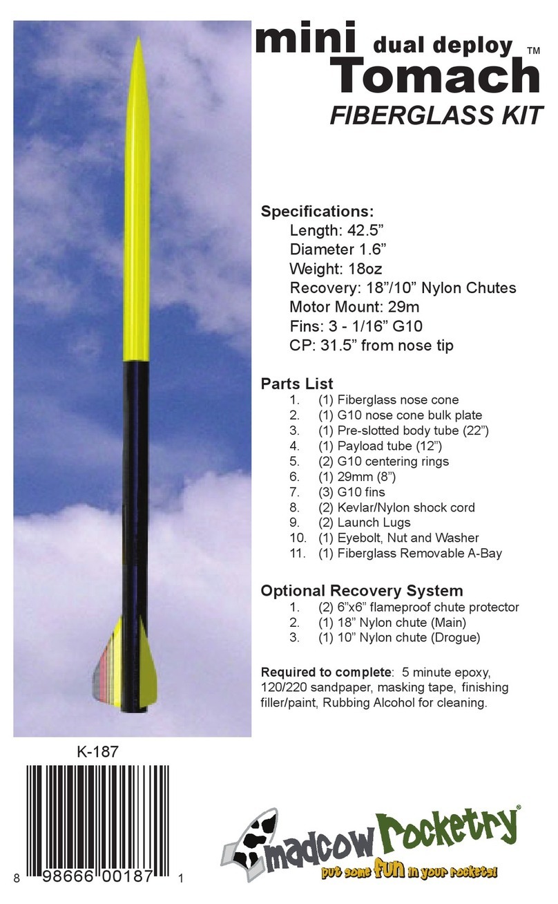
Madcow Rocketry Tomach FIBERGLASS KIT User manual

Madcow Rocketry

Madcow Rocketry Tomach FIBERGLASS KIT User manual

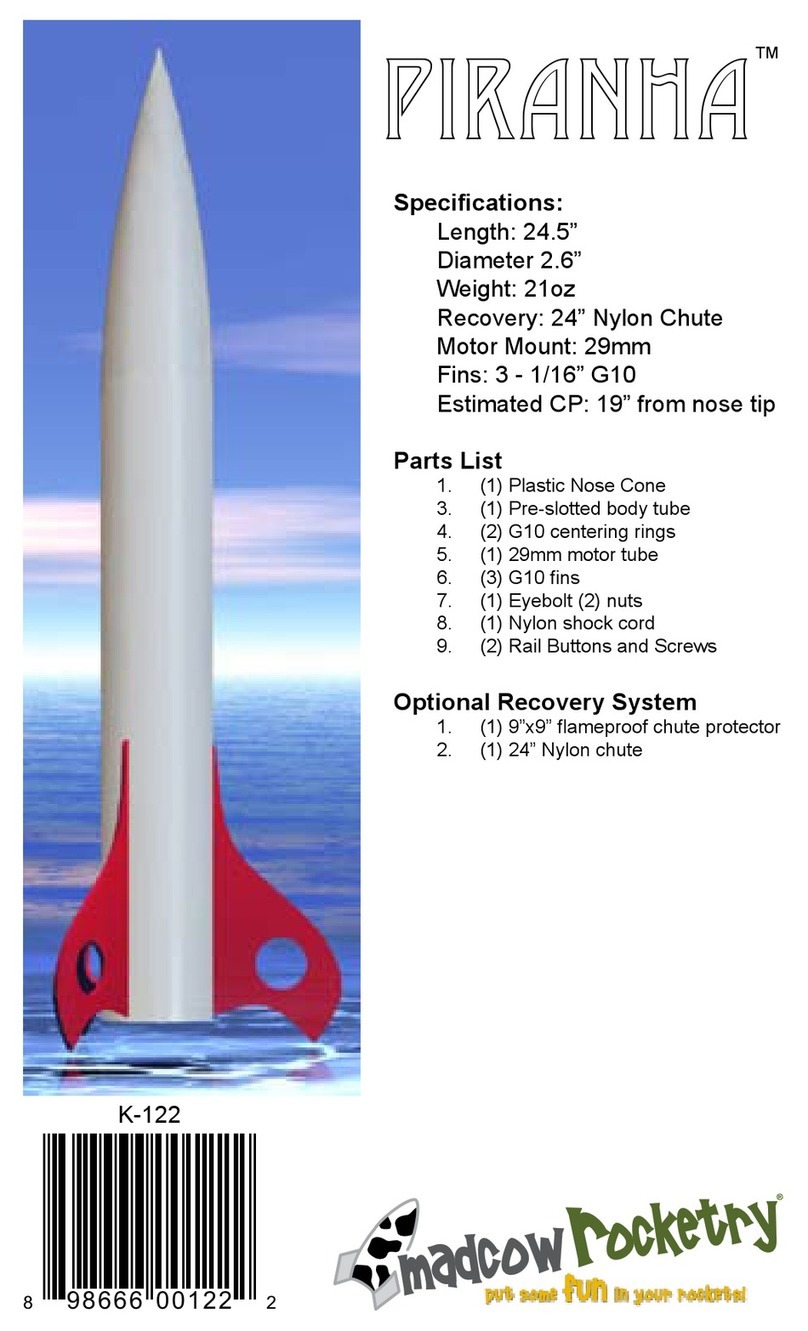
Madcow Rocketry PIRANHA User manual

Madcow Rocketry

Madcow Rocketry PIRANHA User manual

Madcow Rocketry mini Black Brant II User manual

Madcow Rocketry

Madcow Rocketry mini Black Brant II User manual

Popular Toy manuals by other brands

GRAUPNER Yak 55 M Gernot Bruckmann Design Building instructions

GRAUPNER

GRAUPNER Yak 55 M Gernot Bruckmann Design Building instructions

Mega Bloks Despicable Me Hydrant Crush DPG67 Assembly instructions

Mega Bloks

Mega Bloks Despicable Me Hydrant Crush DPG67 Assembly instructions

Hasbro Spiderman Battle Action Triple Blast Hover Jet... Assembly instructions

Hasbro

Hasbro Spiderman Battle Action Triple Blast Hover Jet... Assembly instructions

Thames & Kosmos Ultra Bionic Blaster manual

Thames & Kosmos

Thames & Kosmos Ultra Bionic Blaster manual

Lionel AMC/ARC Log Loader owner's manual

Lionel

Lionel AMC/ARC Log Loader owner's manual

Fisher-Price COLOR ME GEMZ N1128N1128 instruction sheet

Fisher-Price

Fisher-Price COLOR ME GEMZ N1128N1128 instruction sheet

Hasbro NERF ELITE 2.0 FLIPSHOTS FLIP-8 manual

Hasbro

Hasbro NERF ELITE 2.0 FLIPSHOTS FLIP-8 manual

AeroPlus A?G030010A Assembly manual

AeroPlus

AeroPlus A?G030010A Assembly manual

Hasbro Playskool Pop-Up Rollin' Ramp Quick start quide

Hasbro

Hasbro Playskool Pop-Up Rollin' Ramp Quick start quide

wobbel Wobbel360 user manual

wobbel

wobbel Wobbel360 user manual

Freewing A 18E instruction manual

Freewing

Freewing A 18E instruction manual

Fraser Hill Farm Haunted Hill Farm HHSPD-12FLSA Assembly instructions

Fraser Hill Farm

Fraser Hill Farm Haunted Hill Farm HHSPD-12FLSA Assembly instructions

Fisher-Price Shakira First Steps Kick & Play Piano Gym manual

Fisher-Price

Fisher-Price Shakira First Steps Kick & Play Piano Gym manual

PARKZONE Conscendo Advance instruction manual

PARKZONE

PARKZONE Conscendo Advance instruction manual

Parkside PP 1050 A1 Operation and safety notes

Parkside

Parkside PP 1050 A1 Operation and safety notes

Dynaflite Talon instruction manual

Dynaflite

Dynaflite Talon instruction manual

marklin BR 89.0 manual

marklin

marklin BR 89.0 manual

Disney FROZEN KID'S DOUBLE MIC KARAOKE SPEAKER instruction manual

Disney

Disney FROZEN KID'S DOUBLE MIC KARAOKE SPEAKER instruction manual

manuals.online logo
manuals.online logoBrands
  • About & Mission
  • Contact us
  • Privacy Policy
  • Terms and Conditions

Copyright 2025 Manuals.Online. All Rights Reserved.