The Handy THTD User manual

www.thehandy.co.uk
23/03/2022 v4
40” (101CM)
TOWED DETHATCHER
MODEL NO: THTD -- PRODUCT NO: 1938118001
EN - ORIGINAL INSTRUCTIONS
ASSEMBLY REQUIRED
SAVE THESE INSTRUCTIONS
SPARES & SUPPORT: 01793 333212
FOR YOUR SAFETY
Please read & understand this manual, paying attention to the safety instructions, before use.
Incorrect use of the product could put the operator or machine in danger.
Whilst every effort has been made to ensure the accuracy of information contained in this manual, our
policy of continuous improvement determines the right to make modifications without prior warning.
Images used are for illustration purposes only
INSTRUCTION MANUAL

Copyright Notice
Copyright © Handy Distribution
Permission is granted to reproduce this publication for personal & educational use only.
Commercial copying, redistribution, hiring or lending is prohibited.
No part of this publication may be stored in a retrieval system or transmitted in any other form or means without
written permission from Handy Distribution.
In all cases this copyright notice must remain intact.

CONTENTS
SPECIFICATIONS
IMPORTANT INFORMATION
GENERAL SAFETY INSTRUCTIONS
SET UP & PREPARATION FOR OPERATION
ASSEMBLY
OPERATION & ADJUSTMENT
MAINTENANCE
PARTS DIAGRAM & LIST
WARRANTY
NOTES
WARNING
Read this instruction manual carefully before operating this machine. Make sure that you are familiar
with the controls and properly operate the machine. Following these instructions can reduce the risk
of personal injury.
ASSEMBLY IS REQUIRED
This product requires assembly before use. See the “Assembly” section for instructions.
Please check that all parts required for the assembly of this dethatcher are included. If for any reason
you believe a part for the assembly is missing or damaged, please contact us.
Tools Required:
2x 1/2" Wrenches
1x 9/16" Wrench
1x 3/4" Wrench or Adjustable Wrench
1x Pliers

SPECIFICATIONS
The manufacturer reserves the right to change the product specification and livery according to continued
product improvements.
Model
THTD
Product Number
1938118001
Weight
14kg
Working Width
40” (101cm)
Recommended Tow Hitch Height
14 - 17cm
Spring Loaded Steel Tines
10 x 100mm
Consistent with our policy of continuous improvement, The Handy reserves the right to change the design and
configuration of any of its products without notice or obligation. Therefore, please treat the text and images in
this manual for illustrative purposes only. They may in no case serve as a basis for any legal claim.
If you require any assistance with regards to the contents or operation of your machine, please contact us:
Tel: 01793 333212, option 2
Opening Hours Weekdays: (CLOSED WEEKENDS & BANK HOLIDAYS)
February to October 8:00am - 5:00pm - November to January 8:30am - 5:00pm
IMPORTANT INFORMATION
IF NOT USED PROPERLY THIS MACHINE CAN BE DANGEROUS!
This machine can cause serious injury to the operator and others, the warning and safety instructions must be
followed to ensure reasonable safety and efficiency in using this product. The operator is responsible for
following the warning and safety instructions in this manual and on the machine. Never use the product unless
the fixing screws or guards are correctly positioned.
DESIGNED FOR DOMESTIC USE ONLY.
The Towed Dethatcher is designed for use in private gardens, whose annual use does not generally exceed 50
hours and is to be primarily used on LAWNS, but not in public facilities, parks, or sports grounds and not for
agricultural or forestry use.
Compliance with this manual supplied by the manufacturer is a prerequisite for the proper usage of the
machine. The operating manual contains servicing and maintenance instructions as well as directions for use.
TRAINING
Read the instructions carefully: Be familiar with the controls and the proper use of the equipment.
Never allow children or people unfamiliar with these instructions to use the product. Local regulations can
restrict the age of the operator.
Never operate while people, especially children, or pets are nearby.
Keep in mind that the operator or user is responsible for accidents or hazards involving the machine that occur
to other people or their property.

GENERAL SAFETY INSTRUCTIONS
It is important that you read and understand the owner’s manual and labels affixed to the machine. Learn its
application and limitations as well as the specific potential hazards. Retain these instructions for future
reference. The operator is responsible for following the warnings & instructions in this manual and on the
product.
Read & understand operator’s
manual before using the machine.
Failure to follow instructions could
result in death or serious injury.
Wear foot protection
Wear protective gloves to protect
your hands
Keep bystanders away
Keep guards in place and in working
order. Replace damaged, missing,
or failed parts before using it.
Risk of slicing. Keep hands
out of the way of all
moving parts.
Safety alert symbol. Used to alert
you to potential personal injury
hazards. Obey all safety messages
that follow this symbol to avoid
possible injury.
DANGER
Indicates an imminently
hazardous situation which,
if not avoided, will result
in serious injury.
WARNING
Indicates a potentially hazardous
situation which, if not avoided,
could result in serious injury
CAUTION
Indicates a potentially
hazardous situation which,
if not avoided, may result
in minor or moderate
injury.
CAUTION
Used without the safety alert
symbol indicates a potentially
hazardous situation which, if not
avoided, may result in property
damage.
IMPORTANT SAFETY WARNINGS
WARNING
Read all safety warnings and all instructions!
Failure to follow the warnings and instructions may result in serious injury. Save all warnings and
instructions for future reference.
WORK AREA SAFETY
a) Keep work area clean and well lit. Cluttered or dark areas invite accidents.
b) Keep children and bystanders away while operating a power tool. Distractions can cause you to lose
control.
PERSONAL SAFETY
a) Read the tow vehicle owner’s manual and vehicle safety rules to know how to operate the vehicle before
using this equipment.
b) Stay alert, watch what you are doing and use common sense when operating. Do not use whilst you are
tired or under the influence of drugs, alcohol, or medication. A moment of inattention while operating
may result in serious personal injury.
c) Use personal protective equipment. Always wear hard wearing gardening gloves and foot protection.
Protective equipment such as dust mask, nonskid stout shoes, hard hat, or hearing protection used for
appropriate conditions will reduce personal injuries.
d) Prevent unintentional starting. Ensure the towing vehicle is switched off, when undertaking, cleaning,
servicing, or repairs.

e) Do not overreach. Always keep proper footing and balance. This enables better control in unexpected
situations.
f) Dress properly. Do not wear loose clothing or jewellery. Keep your hair, clothing, and gloves away from
moving parts. Loose clothes, jewellery or long hair can be caught in moving parts.
TOOL USE AND CARE
a) Do not force the tool. Use the correct tool for your application. The correct tool will do the job better and
safer at the rate for which it was designed.
b) Store idle tools out of the reach of children and do not allow persons unfamiliar with the tool or these
instructions to operate. It can be dangerous in the hands of untrained users.
c) Maintain tools. Check for misalignment or binding of moving parts, breakage of parts and any other
condition that may affect the tool’s operation. If damaged, have the tool repaired before use.
d) Many accidents are caused by poorly maintained power tools.
e) Use the power tool, accessories, and tool bits etc. in accordance with these instructions, considering the
working conditions and the work to be performed. Use of the power tool for operations different from
those intended could result in a hazardous situation.
SAFE OPERATION PRACTICES
TRAINING
a) Read the instructions carefully. Be familiar with the controls and the correct use of the machine.
b) Never allow children or people unfamiliar with these instructions to use the machine. Local regulations
can restrict the age of the operator.
c) Keep in mind that the operator or user is responsible for accidents or hazards occurring to other people or
their property.
PREPARATION
d) Read the tow vehicle owner’s manual and vehicle safety rules to know how to operate the vehicle before
using this equipment.
e) Before use, always visually inspect the machine for damaged, missing, or misplaced guards or shields.
f) Never operate the machine while people, especially children, or pets are nearby.
g) Do not allow anyone to ride or sit on the dethatcher frame or on the towing vehicle.
OPERATION
f) Wear hard wearing gloves and stout shoes at all times while operating the machine.
g) Avoid using the machine in bad weather conditions.
h) Use the machine only in daylight or good artificial light.
i) Never operate the machine with damaged guards or shields or without guards or shields in place.
j) Switch on the tow vehicle engine only when hands and feet are away from a tow vehicle cutting means.
k) Take care against injury to feet and hands from the tow vehicles cutting means.
l) For ride on mowers, go up and down (NOT side to side). This gives maximum traction to the drive wheels
and lessens the risk of rolling. It also avoids the ‘crabbing’ that tends to happen when mowing crossways
on any slope, where the heavy end of the machine keeps trying to slide downhill making slope use
difficult. This equipment should be operated at reduced speed on rough terrain, along creeks and ditches
and on hillsides, to prevent tipping and loss of control. Do not drive too close to a creek or a ditch. Do not
tow this equipment on a highway or any other public thoroughfare. Always begin with the transmission in
first (low) gear & the engine at low speed. Gradually increase the speed as conditions permit. The vehicle
braking and stability may be affected with the dethatcher attached. Be aware of changing conditions on
slopes. Refer to safety rules in the vehicle owner's manual, concerning safe operation on slopes.
MAINTENANCE AND STORAGE
m) Disconnect the machine from the tow vehicle before carrying out maintenance or cleaning work.
n) Clean the machine immediately after use. Keep the machine clean to ensure it operates to its full & safest
performance.
o) Use only the manufacturer’s recommended replacement parts and accessories.
p) Inspect and maintain the machine regularly. Have the machine repaired only by an authorised repairer.
q) When not in use, the machine should be stored in a dry location, out of direct sunlight. Keep the machine
away from children & others not qualified.

ADDITIONAL SAFETY WARNINGS
PERSONAL SAFETY
DANGER
RISK OF SUFFOCATION
Small parts can be easily swallowed. There is also a risk that a polybag can suffocate toddlers. Keep toddlers
away when you assemble the product. Dispose of all polybags responsibly.
Know how to stop the product quickly in an emergency. Only work in the daylight or when visibility is good.
Check your product before each use. Always visually inspect your grass shear before each use. Check that the
ventilation slots are not obstructed in any way.
Do not overload the product.
WARNING
When wearing hearing protection, the operator may not notice persons approaching.
Always wear suitable clothing, protective gloves, and stout shoes. Always ensure that you have a secure
foothold whilst working. Do not work on slippery surfaces.
DISPOSAL
The garden product, accessories and packaging should be sorted for environmental-friendly recycling. Do not
dispose of garden products, into household waste!
SET UP & PREPARATION FOR OPERATION
This product must be assembled correctly before use. Carefully remove the product and any accessories from
the carton. Inspect the product carefully to make sure there are no breakages or missing items during shipping.
Do not discard the packing material and carton until you have carefully inspected and satisfactorily operated
the product.
WARNING
If any parts are damaged or missing do not operate this product until the parts are replaced. Failure to heed
this warning could result in serious personal injury.
Do not attempt to modify this product or create accessories not recommended for use with this product. Any
such alteration or modification is misuse and could result in a hazardous condition leading to possible
serious personal injury.
Read and follow all instructions for assembly and operation. Failure to properly assemble this equipment
could result in serious injury to the user or bystanders, or cause equipment damage.
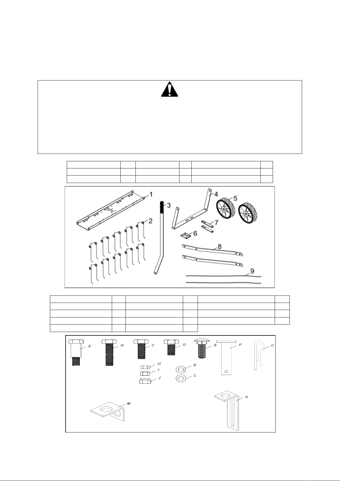
1. Tine Shield (40’’)
1
4. Axle Bracket
1
7. Hitch Brackets
2
2. Spring Tines x10
10
5. Wheels
2
8. Hitch Mount Arms
2
3. Lift Handle
1
6. Lift Plate
1
9. Spring Alignment Wires
2
A. Shoulder Bolt
2
F. Hitch Pin φ10
1
K. Lock Washer φ8
14
B. Hex Bolt M8x50
2
G. Hair Cotter Pin φ3
1
L. Big Flat Washer φ8
10
C. Hex Bolt M8x30
2
H. Hex Nut M8
14
M. Angle Bracket
4
D. Hex Bolt M8x20
15
I. Hex Lock Nut M8
19
N. Hitch Arm Mount Brackets
3
E. Carriage Bolt M8x25
14
J. Hex Lock Nut M10
2
.

ASSEMBLY
Remove the machine and contents from the carton. Be sure the carton is empty before discarding. If you
require any assistance with regards to the contents or operation of your machine, please contact us:
Tel: 01793 333212, option 2
Opening Hours Weekdays: (CLOSED WEEKENDS & BANK HOLIDAYS)
February to October 8:00am - 5:00pm - November to January 8:30am - 5:00pm
STEP 1
Assemble the lift plate to the top of the tine shield using four M8x20 hex bolts and M8 hex lock nuts as shown
in Figure 1. Tighten.
STEP 2
Turn the tine shield upside down. See Figure 2.
STEP 3
Assemble two (tall) hitch arm mount brackets and two (short) angle brackets to the bottom of the tine shield.
Fasten the brackets to the four round holes at the rear of the tine shield using four M8x20 hex bolts and M8
hex lock nuts. Do not tighten yet. See Figure 2.
STEP 4
Insert two angle brackets into the round holes in the bottom of the tine shield at the front. Use two M8x20 hex
bolts and M8 hex lock nuts. Do not tighten yet. See Figure 2.
LIFT PLATE
M8X20
HEX BOLT
M8 HEX
LOCK NUT
HITCH ARM MOUNT
BRACKET
M8 HEX LOCK
NUT
ANGLE
BRACKET
ANGLE
BRACKET
M8X20 HEX
BOLT
FIGURE 1
FIGURE 2

STEP 5
Fasten the hitch mount arms to the outside of the angle brackets at the front of the tine shield. Use two
M8x20 hex bolts and M8 hex lock nuts. Tighten and then loosen the nuts slightly. See Figure 3.
STEP 6
Fasten the hitch mount arms to the outside of the hitch arm mount brackets at the rear of the tine shield. Use
two M8x25 carriage bolts, Ø8 lock washers and M8 hex nuts. Do not tighten yet. See Figure 3.
STEP 7
Connect the front ends of the hitch mount arms using two M8x30 hex bolts and M8 hex lock nuts. Do not
tighten yet. See Figure 4.
STEP 8
Attach the hitch brackets to the top and bottom of the hitch mount arms using two M8x50 hex bolts and M8
hex lock nuts. Do not tighten yet. See Figure 4.
STEP 9
Assemble the Ф10 hitch pin through the hitch brackets and secure it with a Ф3 hair cotter pin. See Figure 4.
FIGURE 3
FIGURE 4
STEP 10
Tighten the bolts and nuts assembled in step 8.
Tighten the bolts and nuts assembled in step 7.
Tighten the bolts and nuts assembled in step 3.
Tighten the bolts and nuts assembled in step 4.
Tighten and then loosen slightly the bolts and nuts assembled in step 5.
Tighten the bolts and nuts assembled in step 6.
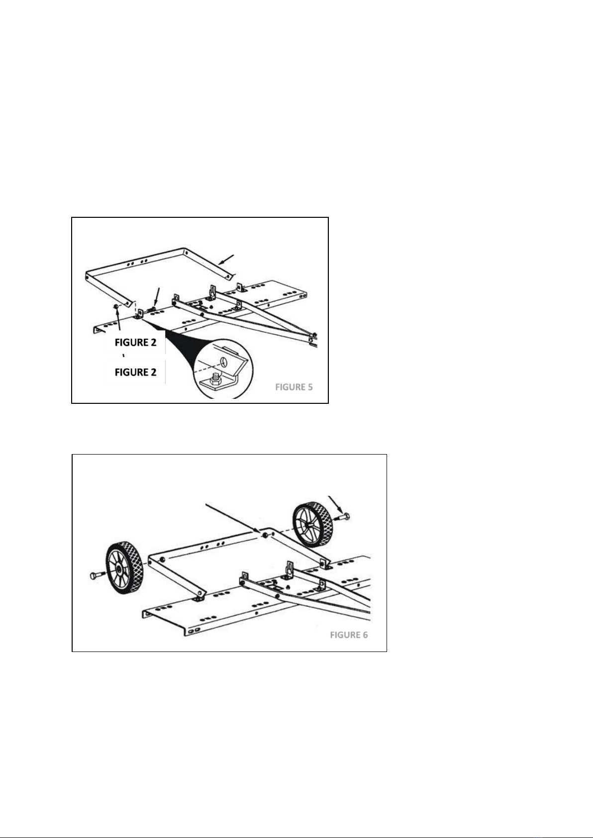
STEP 11
Attach the axle bracket onto the outside of the angle brackets using two M8x20 hex bolts and M8 hex lock
nuts. The ends of the axle bracket must point as shown in Figure 5. Tighten and then loosen the bolts and nuts
slightly.
STEP 12
Assemble the wheels to the axle bracket using two shoulder bolts and two M10 hex lock nuts. Tighten. See
Figure 6.
AXLE BRACKET
M8X20 HEX BOLT
M8 HEX LOCK NUT
M10 HEX
LOCK NUT
SHOULDER BOLT
FIGURE 5
FIGURE 6
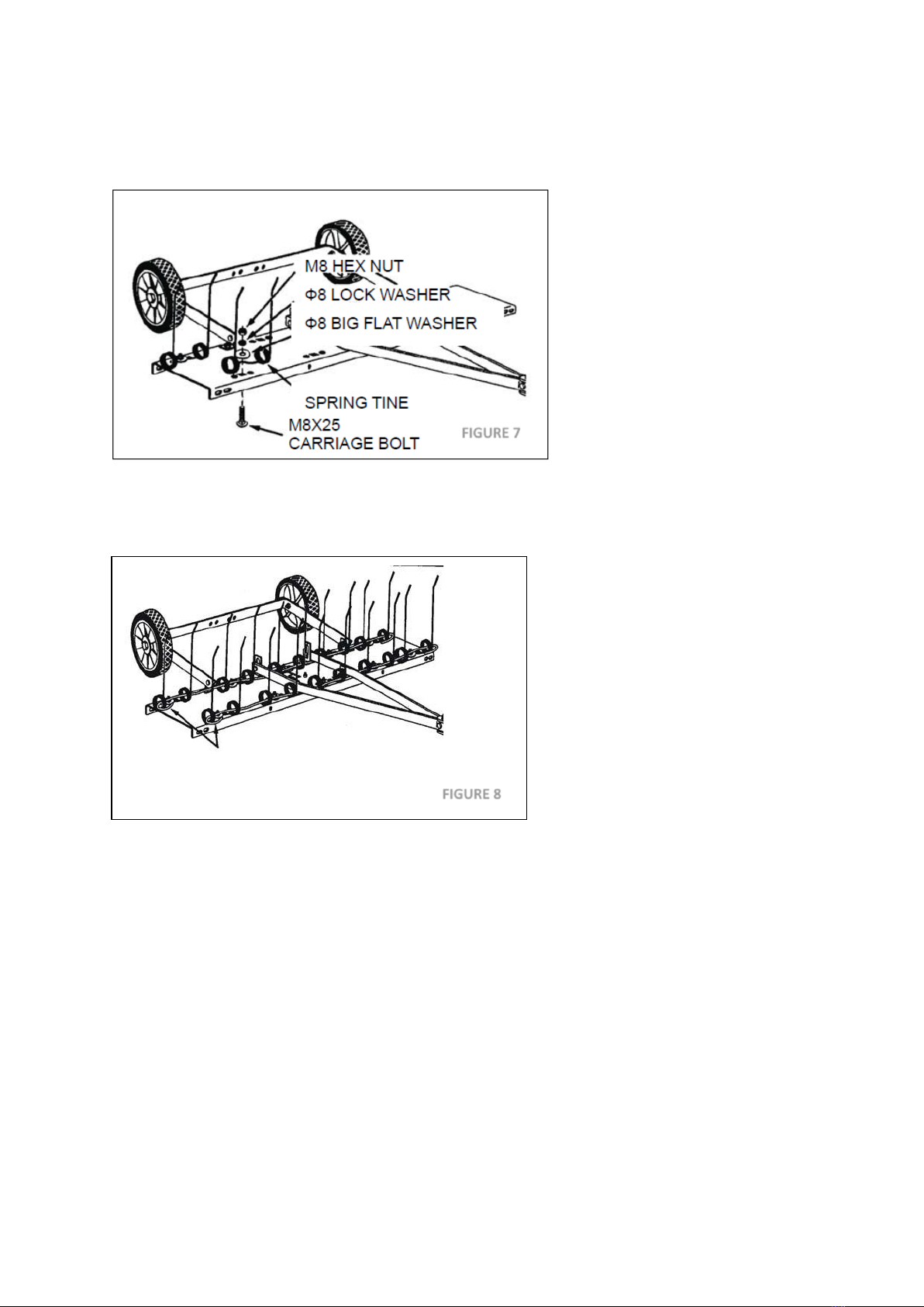
STEP 13
Fasten the ten spring tines to the square holes in the bottom of the tine shield. Use a M8x25 carriage bolt, Ф8
big flat washer, Ø8 lock washer and M8 hex nut for each spring tine. Tighten. See Figure 7. NOTE: Spring tines
must sit between dimples.
STEP 14
Thread the spring align wires through the front and rear rows of spring tines, passing the wires in between the
hitch mount arms and the tine shield. Bend the ends of the wires to secure them.
See Figure 8.
STEP 15
Attach a hitch arm mount bracket to the axle bracket using two M8x25 carriage bolts, Ø 8 lock washers and M8
hex nuts. Do not tighten yet. See Figure 9.
STEP 16
Insert the lift handle through the tine shield. Attach it to the just assembled hitch arm mount bracket using
M8x20 hex bolt and a M8 hex lock nut. Tighten. See Figure 9.
SPRING ALIGN WIRE
FIGURE 7
FIGURE 8
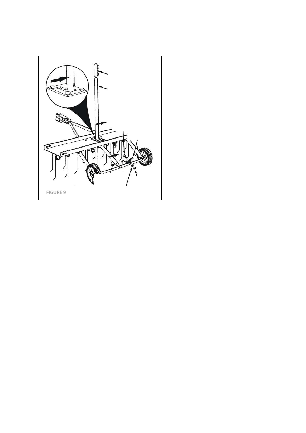
STEP 17
Position the hitch arm mount bracket so that some resistance is felt through the lift handle when it is locked in
the up position. Tighten the nuts. See Figure 9.
GRIP
LIFT HANDLE
M8X25
CARRIAGE BOLT
M8X20 HEX
BOLT
M8 HEX
LOCK NUT
Ø 8 LOCK
WASHER
M8
HEX
NUT
FIGURE 9
OPERATION / ADJUSTMENT
DANGER
The product must only be put into operation if no defects are found. It is crucial that defective parts are
replaced before the product is used again. Check the safety equipment and the safe condition of the
product: Check all parts to make sure that they fit tightly. Check whether there are any visible defects:
broken parts, cracks, etc.
Regular removal of thatch is critical to the maintenance of a healthy lawn. Thatch is a layer of stems, clippings,
runners, roots and leaves that have not decayed. Excessive thatch prevents air, water and fertilizer from
reaching the roots. The dethatcher effectively dislodges excessive thatch from your lawn. Read these
instructions to help avoid improper adjustment and operation.
Correct adjustment of the tine shield and spring tines is important for effective performance. Refer to the
following steps for the proper adjustment before operating the dethatcher.
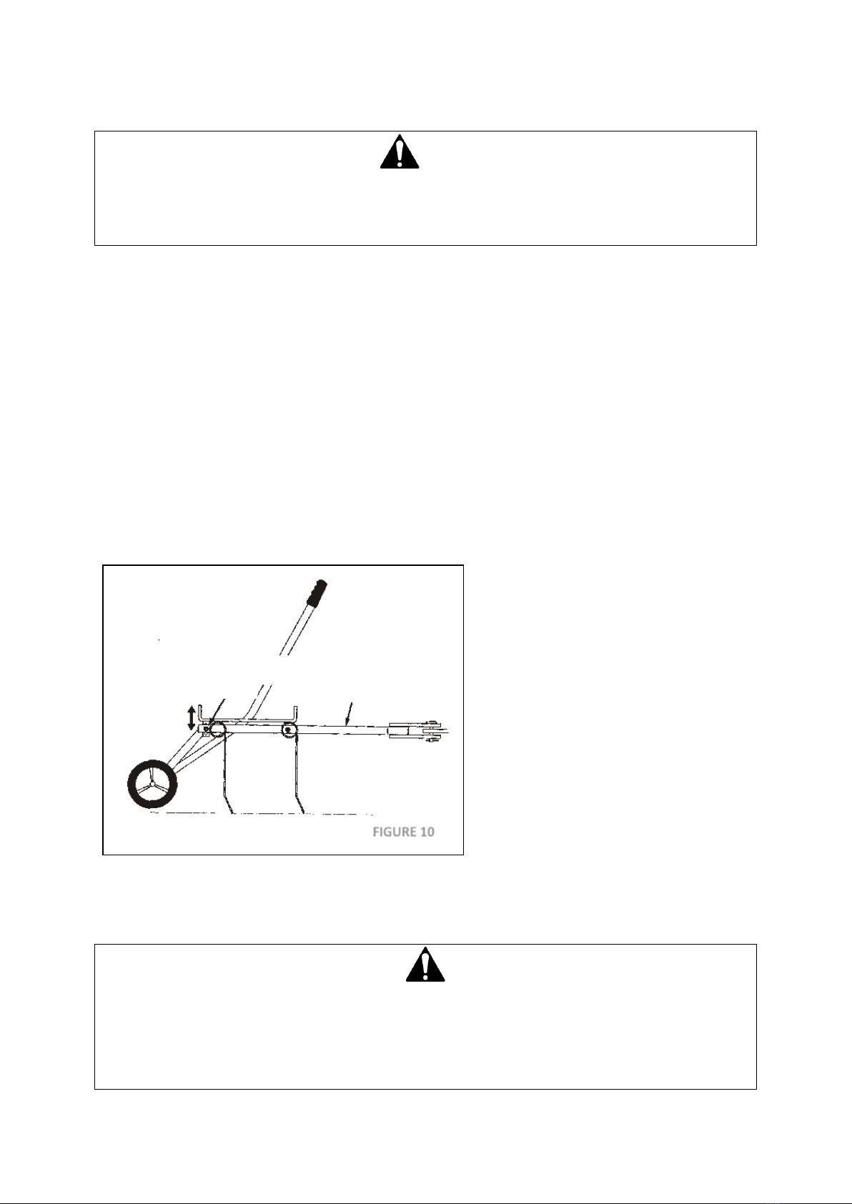
•Move the towing vehicle onto a level surface, such as a driveway or garage floor and attach the tine de-
thatcher to the vehicle hitch. See Figure 10. Recommend towing vehicle hitch height is 14-17cm.
•To adjust the spring tine shield, lower the de-thatcher into the operating position using the lift handle.
Loosen the two hex nuts and carriage bolts which fasten the rear of the hitch mount arm to the hitch arm
mount brackets. Adjust the tin shield until it is level and both the front and rear spring tines are in contact
with the ground. Re-tighten the hex nuts. See Figure 10.
•The wheels of the dethatcher will remain in contact with the ground at all times.
•Vary the vehicle's forward speed until the best dethatching action is achieved.
•For best results, use a crisscross pattern on your lawn.
ADDING EXTRA WEIGHT
If the dethatcher appears to be jumping during use, extra weight (max 70lbs/31.75kg) should be added to the
tine shield. Attach and secure weights (Concrete blocks are recommended) to each side of the tine shield using
rubber tie down straps.
DANGER
Vehicle braking and stability may be affected with the attachment of this machine to your garden vehicle.
Always operate up and down a slope, never across the face of a slope.
Do not work on slopes greater than 10°.
Drive slowly & carefully, especially when turning and on uneven ground.
Do not tow this equipment on a highway or any other public thoroughfare.
CARRIAGE BOLT & HEX NUT
HITCH
MOUNT
ARMS
FIGURE 10

MAINTENANCE
LUBRICATE
Maintenance spray or multi-purpose grease can be applied to the wheel axle prior to long-term storage.
CLEANING
After each use thoroughly wash the machine with a stiff brush.
STORING
Before storing, ensure that the machine is clean and dry.
Store in a dry or protected area and coat exposed metal with light oil when not in use.
CHECK ALL NUTS, BOLTS AND FASTENING
Before each use check all fastenings are tight & secure.
APPEARANCE
If rust appears on the shield or spring tines, sand lightly and coat with enamel paint.
NEVER EXCEED LOAD CAPACITY
To avoid damaging the dethatcher, never exceed the rated load capacity of max 70lbs/31.75kg
ONLY USE MANUFACTURER APPROVED PARTS
If a part needs replacing, only use the manufacturer’s original parts. Non-original replacement parts will
invalidate your warranty and may result in a safety hazard or poor operation.

PARTS DIAGRAM & LIST
No.
Part No.
Description
QTY
No.
Part No.
Description
QTY
1
TH153-1
Hitch Arm Mount Bracket
3
13
TH153-13
Hex Lock Nut M10
2
2
TH153-2GM
Hitch Bracket
2
14
TH153-14
Flat Washer
10
3
TH153-3
Spring Tine
10
15
TH153-15
Hex Bolt M8x20
15
4
TH153-4
Spring Alignment Wire
2
16
TH153-16
Lock Washer
14
5
TH153-5
Wheel
2
17
TH153-17
Hex Nut M8
14
6
TH153-6GM
Tine Shield
1
18
TH153-18
Hex Lock Nut M8
19
7
TH153-7GM
Hitch Mount Arm
2
19
TH153-19
Carriage Bolt M8x25
14
8
TH153-8
Gate Plate
1
20
TH153-20
Handle Grip
1
9
TH153-9GM
Axle Bracket
1
21
TH153-21
Hex Bolt M8x50
2
10
TH153-10GM
Lift Handle
1
22
TH153-22
Hex Bolt M8x30
2
11
TH153-11
Shoulder Bolt
2
23
TH153-23
Hitch Pin M8
1
12
TH153-12
Angle Bracket
4
24
TH153-24
R Clip
1
NOTE: Parts Lists are supplied for information purposes only, not all parts are stocked individually & we recommend
you contact our Spares Team on 01793 333212 for expert advice.

GJ HANDY (TRADING) LTD USER WARRANTY POLICY
Users Statement of Warranty
Each new machine is warranted against defective material or assembly of material under normal usage. The
warranty applies to the original purchaser and covers faulty parts and the labour involved in replacing and
repairing those parts, which are of original manufacture.
Period of Warranty
The Handy (Petrol & Electric only), Webb (excludes Dynamic, Heritage, Legacy),
a) 2 years from the original date of sale to the first domestic user.
b) 90 days from the original date of sale to the professional/commercial user.
c) 90 days from the original date of sale when used for hire.
d) A reduced warranty period of 90 days applies to those items which are subject to normal wear and tear
(e.g., but not limited to wheels, tyres, cutter bars, cylinders, cutting blades, blade boss, belts, cables, nylon
line & spool, collection bags, spark plugs).
e) Engines are supplied with a separate warranty to the machine. The engine manufacturers warranty
statement which will be supplied within the engine instruction manual. All enquiries and warranty repairs
should be discussed with the engine manufacturer or approved warranty repair dealer.
f) 90 days from the original date of purchase for Replacement Spare Parts (unless normal wear & tear
component, which are covered for 30 days).
g) All machines’ must be serviced within the first 12 months from the original date of purchase to comply
with the warranty (if applicable), failure to do so will invalidate the 2nd year of the warranty.
Webb Dynamic, Heritage & Legacy, Handy (All non-Petrol & Electric), Mowerland, Q-Garden
a) 1 year from the original date of sale to the first domestic user.
b) 90 days from the original date of sale to the professional/commercial user.
c) 90 days from the original date of sale when used for hire.
d) A reduced warranty period of 90 days applies to those items which are subject to normal wear and tear
(e.g., but not limited to wheels, tyres, cutter bars, cylinders, cutting blades, blade boss, belts, cables, nylon
line & spool, collection bags, spark plugs).
e) Engines are supplied with a separate warranty to the machine. The engine manufacturers warranty
statement which will be supplied within the engine instruction manual. All enquiries and warranty repairs
should be discussed with the engine manufacturer or approved warranty repair dealer.
f) 90 days from the original date of purchase for Replacement Spare Parts (unless normal wear & tear
component, which are covered for 30 days).
All warranty repairs must be undertaken by an authorised service dealer. These dealers have been accredited
by GJ Handy (Trading) Ltd and agree to only use genuine parts and follow our repair procedures.
Not covered by this warranty
a) The warranty policy does not cover any depreciation or damages caused by ordinary wear, rusting or
corrosion, lack of correct maintenance or operation, misuse, abuse, lack of transportation or accident.
b) The warranty policy does not cover any costs necessary for the standard periodic maintenance services
instructed by the operator’s manual, or service parts replacement which would include oil, filters, tyres,
belts, brake linings, fuses, blades, seals, and other service parts unless it can be proven that the item has
evidence of faulty manufacture.
c) The warranty policy will not cover failure or damage caused as a result of parts or accessories being
modified without the written approval of GJ Handy (Trading) Ltd.
d) The warranty policy will not cover the unit if non-genuine parts have been fitted and as a result damage
has occurred to the unit.
e) The warranty policy is non-transferable and is only applicable to the original purchaser.

Disclaimer
a) This warranty is only a remedy for defect of products. GJ Handy (Trading) Ltd will never warranty in terms
of the merchantability or the fitness for a particular purpose.
b) No person is authorised to make any warranties, representations or promises, expressed or implied, on
behalf of GJ Handy (Trading) Ltd, or to modify the terms conditions or limitation of this warranty policy in
any way.
c) Neither GJ Handy (Trading) Ltd nor any company affiliated with GJ Handy (Trading) Ltd shall be liable in any
event or manner whatsoever for incidental or consequential damages or injuries, including, but not limited
to, loss of crops, loss of profit, out of pocket expenses or profits, rental of substitute equipment or other
commercial losses.
General
a) Most warrantable failures show up within the first few weeks of use. These failures are usually
straightforward and warranty assessment is relatively easy.
b) Failures relating to cutter decks and belts need careful investigation, as the cause may not always be
straightforward. Look for damage to blades and pulleys especially when the cutter belt or blade boss have
snapped or cracked as this could be due to impact damage.
c) Customers should always refer to the operator/instruction manual when any disputed problem arises, you
will find most areas covered within the manual.


For spares or support of your handy product,
please contact us:
Tel: 01793 333212
Opening Hours Weekdays:
February to October 8:30am - 5:30pm
November to January 8:30am - 5:00pm
(CLOSED WEEKENDS & BANK HOLIDAYS)
To see our range of garden machinery & equipment visit:
www.thehandy.co.uk
Making gardening easier & affordable since 1938
Distributed by Handy, Murdock Road, Dorcan, Swindon, SN3 5HY
This manual suits for next models
1
Table of contents
Popular Irrigation System manuals by other brands


Johnson Controls
Johnson Controls tyco ESFR-34 manual

Duramaxx
Duramaxx Sprizzz manual

Reliable
Reliable RFC43 LL Application and Installation

CENTRAL
CENTRAL ESFR-1 quick start guide

Hunter
Hunter X-CORE Owners manual and programming instructions

Tyco Fire Product
Tyco Fire Product Star Galaxy SGQR instruction manual

Rain Bird
Rain Bird LG3HE Installation & operating guide

Tyco
Tyco TY-FRB Series Operation

Reliable
Reliable RFC43 quick start guide

Tyco Fire Product
Tyco Fire Product CENTRAL DS-1 instruction manual

Tyco
Tyco Rapidresponse LFII Series General description

Bocciolone Anticendio
Bocciolone Anticendio 920/A Technical bulletin