The Handy THPWBBV Installation and maintenance instructions

Page 1
OPERATOR’S MANUAL AND PARTS LIST
PETROLWHEELED VACUUM - THPWBBV
Sales & Helpline 01793 333220
www.thehandy.co.uk
Before use please read & understand this manual, paying particular
attention to the safety instructions.
2010 v1

Page 2
CONTENTS
SAFETY INSTRUCTIONS 3
SPECIFICATIONS 4
FUEL 4
FEATURES 5
ASSEMBLY 6-7
OPERATION 8
MAINTENANCE 9
TROUBLE SHOOTING 10
PARTS DIAGRAM AND LIST 11-12
EC DECLARATION OF CONFORMITY 13

Page 3
SAFETY INSTRUCTIONS
Read and understand the owner’s manual and labels afxed to the
vacuum shredder. Learn its application and limitations as well as the
specic potential hazards. Retain these instructions for reference.
• Use sturdy footwear and wear eye and ear protection.
Wear heavy duty gloves, preferably made of leather.
• Do not operate the machine if you are tired,ill or under the inuence of
alcohol or drugs.
• Do not smoke when using the vacuum shredder and ensure caution
when handling fuel. We recommend you fuel the machine at least 3m
away from where you wish to work in case any spilt fuel ignites when
starting the engine.
• Ensurethatbystanders,childrenandpetskeepwellawaywhenstarting
or shredding - at least 25m.
• Inspect the machine before each use for any worn or damaged parts.
Do not use until the parts are repaired or replaced. Check that nuts,
screws and bolts are securely fastened.
• Have a clear work area and secure footing and do not operate the
machine in an enclosed area.
• Do not operate without bag and vacuum nozzle or optional hose kit in
place.
• Keep your hands and feet out of inlet and discharge openings while
machine is running.
• Take care that pieces of metal objects are not fed into the machine.
• If there is any vibration or abnormal noise coming from the machine
during operation, switch off immediately and investigate before
shredding any more material.
• Please recycle the cardboard packaging in which the vacuum shredder
is delivered.
Always shut off the engine before moving it or attempting to clear
any blockage.

Page 4
SPECIFICATIONS
FUEL
The vacuum shredder is supplied without petrol or oil.
Petrol is very ammable. Avoid smoking or fuelling the vacuum shredder any-
where near a ame or sparks. Allow the engine to cool before re-fuelling. Fuel the
engine at least 3m away from your work area.
• Use fresh unleaded petrol and good quality four stroke engine oil ( SAE10W30 or
SAE10W40).
• Refer to the instructions on page 8, together with the separate engine instructions,
for details of fuelling the machine.
• If the vacuum is not going to be used for a long period, drain the mixture from the
fuel tank, start the engine and drain the carburettor of any remaining fuel.
• Dispose of any unwanted oil at an authorised recycling point.
Model THPWBBV
Engine Briggs & Stratton I/C 65
Displacement 206 cm³
Chipper Capacity 7.5cm/3in
Collection Bag Capacity 100 litres
Suction Width 60cm/24in
Blades 2 chipper; 2 hammer
Weight 83kg

Page 5
FEATURES
Features of the Vacuum Shredder:
Chipper Chute: -
Allows twigs and small branches up to 3” in diameter to be fed into the
impeller for chipping.
Tamper Plug:-
This plug is inserted into the chipper chute to push twigs and small
brances towards the impeller blades. Always use the tamper plug, not
your hands.
Gear Adjust Handle:-
The vacuum shredder works in forward or reverse - adjust the handle
to position 1 or 2.
Vacuum Bag:-
Collect shredded or chipped material fed through either the chipper
chute or through the nozzle.
Drive Control:-
The drive control is located on the upper handle. Squeezing the control
engages the rear wheels. Release the control to slow down.
Throttle Control Lever:-
This is located on the upper handle and controls the engine speed.
Also has ON/Off Switch. Refer to the engine manual for forther details.
Engine Controls:-
Refer to separate engine manual for the function of these controls.

Page 6
ASSEMBLY
The vacuum shredder is supplied with the following loose parts in
the box. Please check carefully before you commence construction.
Nozzle; Discharge Chute; Collection Bag; Side Chipping Chute;
Safety Goggles; Ear Protectors; Wrench Plug; Nuts and Bolts.
All references to the right or left side are as viewed from the
operator’s position, unless otherwise stated.
Attaching the Nozzle:
• Remove the three wing nuts from the front of the vacuum.
• Place nozzle in position over three studs on the unit.
• Secure with wing nuts.
Attaching the Handle:
• Remove the four screws xed on both sides of the handle.
• Turn the handles 180 degrees backward as shown in second
picture below.
• Ensure the opening under the handle lines up with the small
oening on the round tube. Fix with bolt.
• Be careful that you do not remove the throttle and switch lines
when adjusting the handles.
• Fix the throttle and switch lines to the handle and make sure
they operate correctly.

Page 7
ASSEMBLY, cont’d
Attaching the Chipping Chute:
• Remove the three hex nuts and washers.
• Place the chipping chute over the weld studs, keeping the
slotted side towards the bottom.
• Loosely secure with the three hex nuts and washers. Do not
fully tighten at this point.
• Align the support bracket with the holes in the right side of the
upper and lower handles. Put the chipping chute on.
• Attach to the handle assembly using hex bolts, washers and
ange nuts.
• Tighten all nuts on the chute, the support bracket and the
handle.
Attaching the Bag:
• Place bag under the upper handle assembly and slip the front
opening on the bag over the discharge chute, making certain it
is over the rim of the discharge chute.
• Fix the bag to the handles and the discharge opening as
shown.

Page 8
OPERATION
Starting the Vacuum Shredder:
• Fill with fuel and oil as directed above.
• Turn the ignition switch on the handle to “I” - On position. Fully close the choke.
• Pull starter cord until the engine res/ignites, the gradually open the choke fully.
• Allow the engine to run for 2 minutes before starting work to allow the engine to
warm up.
• Adjust the throttle as necessary.
Stopping the Vacuum Shredder:
• Reduce the engine speed by adjusting the throttle.
• Turn the ignition switch to “O” - Off position.
Emptying the Collection Bag:
Unzip the collection bag at the rear to empty the contents. Ensure that the zip is
completely closed before re-commencing.
Nozzle Door Height Adjustment:
The nozzle adjustment levers are located on each side of the nozzle door. The door
can be adjusted to one of ve positions, ranging from ½in to 3in ground clearance.
Push the adjustment lever out away from nozzle. Slacken wing nut on each side of
nozzle and move nozzle door to the reuired position. Re-tighten wing nuts.
Note: Height must be adjusted to the same postion on either side.
Cleaning the Flail Screen:
If the discharge area becomes clogged, remove the ail screen and clean area as fol-
lows:
• Stop the engine and allow machine to come to a complete halt.
• Disconnect spark plug lead.
• Remove the collection bag.
• Remove the four sleft-tapping screws from the bottom of the dischrage chute.
• Remove the hex bolt, saddle washer and hex nut from the top and remove the dis-
charge chute assembly.
• Remove the two hex bolts and hex nuts which extend through the impeller housing.
• Lift the ail screen from inside the housing and clean by scraping and/or washing
with water.
• Be careful to reassemble the ail screen with the corved side down.
• Re-attach the discharge chute assembly.

Page 9
MAINTENANCE
After each use, clean off any loose or dry debris which may have accumulated.
Wipe the machine with an oiled rag to prvent rust and prolong life.
Empty the collection bag completely and store in a clean dry area. Do not store next to
corrosive material such as fertiliser.
After a period of time the chipper blades may become blunt. It is possible to sharpen them
but this should be done by an authorised service dealer.
Similarly, over time the “V” belt may need changing. Again this procedure should be carried
out by an authorised service dealer.

Page 10
TROUBLE SHOOTING
Problem Cause Remedy
Engine fails to
start • Spark wire disconnected
• Choke not in CHOKE position
• Fuel tank empty or stale fuel
• Faulty spark plug
• Blocked fuel line
• Engine ooded
• Connect wire
• Move to CHOKE position
• Fill tank with fresh fuel
• Clean, adjust gap or replace
• Clean fuel line
• Wait a few minutes and restart
Engine erratic • Spark plug wire loose
• Blocked fuel line or stale fuel
• Vent blocked
• Water or dirt in fuel system
• Dirty air cleaner
• Carburettor out of adjustment
• Connect and tighten spark plug wire
• Clean fuel line and ll tank with fresh
fuel
• Clear vent
• Drain fuel tank and rell
• Refer to engine manual
• Refer to authorised service dealer
Engine over-
heats • Engine oil level low
• Dirty air cleaner
• Carburettor not adjusted properly
• Fill crankcase with fresh oil
• Refer to engine manual
• Refer to authorised service dealer
Engine
occasionally
misses at high
speed
• Spark plug gap too close
• Carburettor idle mixture incorrect • Adjust gap to 0.030”
• Refer to authorised service dealer
Excessive
Vibration • Loose parts or damaged impeller • Refer to authorised service dealer
Unit does not
discharge • Chute deector blocked
• Foreign object lodged in impeller
• Low engine RPM
• Vacuum bag is full
• Stop engine, disconnect spark plug
and clean out deector
• Stop engine, disconnect spark plug
and remove object
• Always run engine at full throttle
• Empty bag
Rate of dis-
charge slows
or compostion
of material
changes
• Low engine RPM
• Chipper blade dull • Always run engine at full throttle
• Refer to authorised service dealer to
have blade sharpened or changed
Page 11
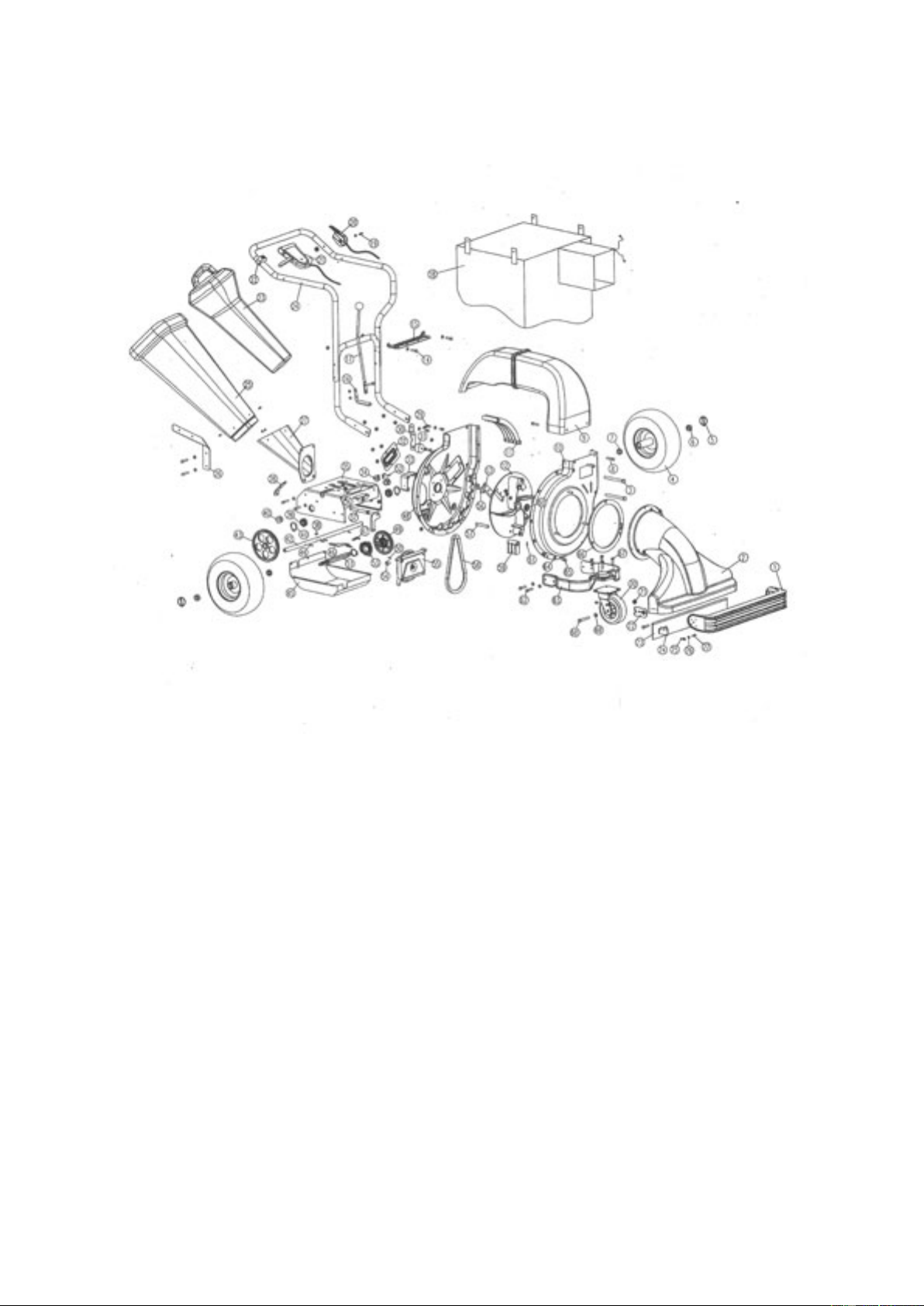
PARTS DIAGRAM

Page 12
PARTS LIST
No Part No Description Qty No Part No Description Qty
1 TH141-1 Lever 1 40 TH141-40 Gearcase Bearing 2
2 TH141-2 Nozzle 1 41 TH141-41 Cir Clip 3
3 TH141-3 Hex Bolt M12x130 2 42 TH141-42 Rear Wheel Axis 1
4 TH141-4 Rear Wheel 2 43 TH141-43 Large Gear 1
5 TH141-5 Cotter Pin 2 44 TH141-44 Spring Roll Pin 4
6 TH141-6 Axle Long Brush 2 45 TH141-45 Bottom Cover 1
7 TH141-7 Axle Short Brush 2 46 TH141-46 Tray Spring Bracket 1
8 TH141-8 Hex Bolt M8x12 2 47 TH141-47 Spring 1
9 TH141-9 Discharge Tube 1 48 TH141-48 Impeller 1
10 TH141-10 Impeller Case (Front) 1 49 TH141-49 Friction Wheel 1
11 TH141-11 Screen 1 50 TH141-50 Spring Roll Pin 1
12 TH141-12 Impeller 1 51 TH141-51 Small Gear Axis 1
13 TH141-13 Blade 2 52 TH141-52 Hex Bolt M6x10 2
14 TH141-14 Hex Bolt M8x40 few 53 TH141-53 Slide Bearing 1
15 TH141-15 Gear Board Two 1 54 TH141-54 Position Control Cover 1
16 TH141-16 Connector 1 55 TH141-55 V Wheel with Clutch 1
17 TH141-17 Gear Adjuster Handle 1 56 TH141-56 Inner Hex Screw M8x25 6
18 TH141-18 Bag 1 57 TH141-57 Hammer Flair 2
19 TH141-19 Hex Bolt M6x50 1 58 TH141-58 V-Belt 1
20 TH141-20 Throttle Control Lever 1 59 TH141-59 Hammer 2
21 TH141-21 Drive LEver 1 60 TH141-60 Blade Press Ring 1
22 TH141-22 Switch 1 61 TH141-61 Spring Roll Pin 2
23 TH141-23 Tamper Plug 1 62 TH141-62 Hex Bolt M8x20 4
24 TH141-24 Handle 1 63 TH141-63 Front Wheel Bracket 1
25 TH141-25 Side Chute 1 1 64 TH141-64 Flat Gasket Few
26 TH141-26 Side Chute Bracket 1 65 TH141-65 Hex Bolt M8x12 Few
27 TH141-27 Side Chute Two 1 66 TH141-66 Nozzle Gasket 1
28 TH141-28 Seat 1 67 TH141-67 Hex Bolt M8x35 4
29 TH141-29 Tension Wheel Spring 1 68 TH141-68 Hex Bolt M12x100 1
30 TH141-30 Tension Wheel Support 1 69 TH141-69 Flat Gasket 3
31 TH141-31 Tension Wheel 1 70 TH141-70 Wheel 1
32 TH141-32 Blade Cover Plate 1 71 TH141-71 Nut M12 3
33 TH141-33 Impeller Case Supporter 1 72 TH141-72 Nozzle Support Plate 2
34 TH141-34 Impeller Bracket 1 73 TH141-73 Leaf Collect Plate 2
35 TH141-35 Gearcase Body 1 74 TH141-74 Nozzle Support Angle 2
36 TH141-36 Bracket 1 75 TH141-75 Flange Nut M6 2
37 TH141-37 Conect Bar 1 76 TH141-76 Flat Gasket Few
38 TH141-38 Key 1 77 TH141-77 Spiral Bolt M6x25 4
39 TH141-39 Bearing 2

Page 13
EC DECLARATION OF CONFORMITY
Declaration of Conformity
Pursuant to the regulations of the following EC Directives:
- Electromagnetic Compatability Directive 89/336/EC amended by 93/68/EC
- Machinery Directive 98/37/EC
- Noise Emissions Directive 2000/14/EC
Handy Distribution Ltd hereby declares that the product
Machine Type: Walk Behind Shredder Chipper
Machine Model: THPWBBV
Mass in kg: 83kg
Engine Displacement: 206 cm³
Conrms to the main safety requirements of the EC Directives listed above.
This conformity is based on the following standards and normative documents:
- EN 13683:2003
- EN 55012:2002
- EN ISO 3744:1995
- ISO 11094:1991
The conformity assessment procedure followed was in accordance with Annex VI of the
Directive 2000/14/EC.
Measured Sound Power Level: 109dB(A)
Guaranteed Sound Power Level: 110 dB(A)
The resonsible person, based within the EC, is identiied below:
Name: Mr Simon Belcher
Title: Managing Director
Company: Handy Distribution Ltd
Address: Hobley Drive, Stratton St Margaret, Swindon, Wiltshire. SN3 4NS
Signature: Date: 17th January, 2008

Page 14
To order spare parts and see the complete range of garden
machinery and garden equipment from Handy, visit:
www.thehandy.co.uk
Table of contents
Other The Handy Vacuum Cleaner manuals


