The Louvre Lounge 4400 User manual

www.louvrelounge.co.nz
4400 Instruction Manual

www.louvrelounge.co.nz | 2
CONTENTS
Required Tools & Man Force
Parts List
Product Description
Safety Disclaimers
Installation
Foundation Installation
Remote Setup
Disassembly
Storage & Disposal
1.
2.
3.
4.
5.
6.
7.
8.
9.
3
4-6
6
7-8
9-18
19-21
22
22
23
ATTENTION: Read this instruction manual
thoroughly before starting installation.
First of all, thank you so much for choosing The Louvre
Lounge to spice up your outdoor space. Please make
sure you've thoroughly studied the instruction manual
before starting installation.
If you have any questions during the installation
process, please email us at [email protected].

REQUIRED TOOLS & MAN FORCE
Man Force
Tools:
Ladder
Tape Measure
Pencil
Spirit Level
Rubber Mallet
Electric Drill
M10/13 Open Wrench (SUPPLIED)
5mm Hexagon Wrench (SUPPLIED)
1.
2.
3.
4.
5.
6.
7.
8.
We recommend installing your Louvre Lounge with 2-3
people although having a third person would make the
installation quicker.
www.louvrelounge.co.nz | 3

PARTS LIST
Before commencing the installation, please confirm all
parts are present. Email us at [email protected]
if you have any issues.
www.louvrelounge.co.nz | 4

PARTS LIST
Hardware:
Aluminium Structure:
www.louvrelounge.co.nz | 5

PARTS LIST
PRODUCT DESCRIPTION
Make the most of your outdoor living area with the 4400
series Louvre Lounge. The motorised louvres and LED lights
transform your outdoor space into the ultimate entertaining
area for you to enjoy for years to come.
www.louvrelounge.co.nz | 6

SAFETY DISCLAIMER'S
WARNING: For the safety of yourself and others, it is
essential to follow all instructions and obey warnings.
Definitions:
This warning triangle calls attention to hazards that
that can lead to death, severe injuries or which are
important for the functioning of the Pergola.
This symbol identifies important notes.
Safety Disclaimer's
You are unsure if the pergola can be installed in the chosen spot
for installation.
You do not understand the instruction manual or parts of it.
You do not have the necessary tools available.
You do not have the necessary technical knowledge
To install this pergola technical knowledge is necessary. Do not
install this pergola yourself instead, contact a professional if:
1.
2.
3.
4.
A minimum of three healthy adults are required to move and install
the pergola as the product is big and heavy. Do not try to install the
pergola alone. If the pergola falls, it could cause serious injuries and
damages! Contact us or a professional for help.
www.louvrelounge.co.nz | 7

Do not install the pergola when you find damaged parts or parts that
are missing. Contact us.
Keep children and pets out of the working area during assembly and
adjustments.
This product and its fixing parts are only suitable for installation on a
plain cement pad. If the concrete pad shows cracks or you require
installation on a wooden deck, please consult a professional before
installation.
Nobody is permitted to change the pergolas’ design and structure
without the permission of us (Louvre Lounge Limited)
Nobody is allowed to climb onto the Pergola. Hanging anything on
the Pergola is forbidden.
The sheeting used to protect the paint must be removed after installation. This
structure is a non-permanent structure, the warranty does not cover damage
incurred under extreme weather conditions including heavy rain, high winds or
if exposed to high heat from heaters or BBQs. Please refer to the warranty
policy for more information.
Safety precautions should always be followed when assembling and using this
product to reduce the risk of personal injury and damage to equipment. Never
leave children unattended around/under this pergola. Do not attempt to
assemble or use the pergola in moderate or heavy wind conditions.
Always secure the pergola and keep the louvres open during heavy winds or
extreme weather to avoid damage to the pergola or personal injury.
www.louvrelounge.co.nz | 8

Attach base plate③x4 to the bottom of posts (C-1 x1,
C-2 x1, C-3 x1 and C-4 x1), use bolts ①x8 to attach using
hex key or electric drill.
C-1 & C-3 and C-2 & C-4 posts need to be installed
diagonally.
Refer to the diagram below.
INSTALLATION
Step 1:
www.louvrelounge.co.nz | 9

www.louvrelounge.co.nz | 9www.louvrelounge.co.nz | 10
a. Remove bolts ⑥ from each post and set them aside.
A total of 24 bolts should be set aside.
b. Attach the beams to the posts as shown in the
diagram. Use the bolts previously set aside to fasten
the beams.
INSTALLATION
Step 2:

Attach the upright covers ④x4 to the top of each post.
Use bolts ⑥x8 to fasten.
INSTALLATION
Step 3:
www.louvrelounge.co.nz | 9www.louvrelounge.co.nz | 11

Use bolts ⑥x4 to fasten beam A-5 as shown in the
diagram.
INSTALLATION
Step 4:
www.louvrelounge.co.nz | 9www.louvrelounge.co.nz | 12

Attach all eight gutters (B-1 x4, B-2 x2 and B-3 x2) by
slotting them on the inside of all beams.
Please refer to the diagram below.
INSTALLATION
Step 5:
www.louvrelounge.co.nz | 9www.louvrelounge.co.nz | 13
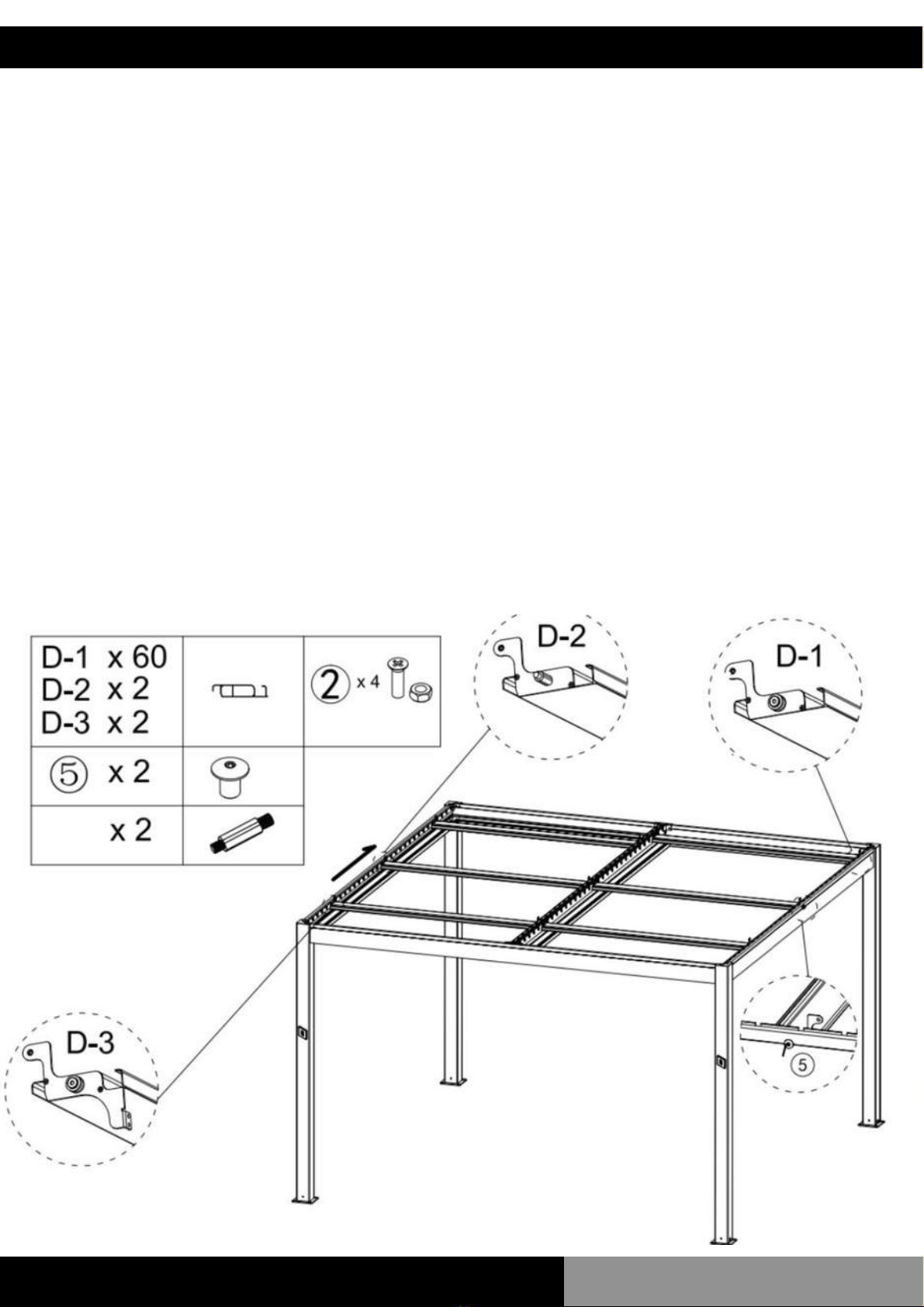
Locate the holes in the centre of beams(A-2, A-3 and
A-5).
Place the strength louvre D-2 into the groove which
lines up with the holes on the beams. Using the M10 nut
⑤X2, secure the louvre in place on both sides.
Place the driving louvre D-3 in line with the 7th groove
on the beams. Fit all common louvres D-1X60 into the
remaining grooves on the beams.
INSTALLATION
Step 6:
www.louvrelounge.co.nz | 9www.louvrelounge.co.nz | 14

a. Unscrew the 4 bolts on both B-2 beams where the
motors will be positioned and set aside. Fasten both
motors ⑨ and ⑩ to beams A-2 and A-3 with the 4 bolts
previously set aside.
b. Next, fasten the motor to the driving louvre from
step 6 using ②. Make sure louvres are closed when
completing this step.
Refer to the diagram below.
INSTALLATION
Step 7:
www.louvrelounge.co.nz | 9www.louvrelounge.co.nz | 15

Attach the control rods
Ⓔ
x4 to each side of the
pergola by placing the plastic spacer ⑦ between the
control rod and the louvre's, threading the bolt ⑥
through from the control rod side and tightening with
a nut ⑧.
Repeat the process until all louvres are secured to the
control rods on both ends.
NOTE: Do not over-tighten. Over-tightening will prevent
louvers from moving.
INSTALLATION
Step 8:
www.louvrelounge.co.nz | 9www.louvrelounge.co.nz | 16

Place a rubber gutter connector
⑫
in each of the four
corners to seal the gutters. Next, place the 50 to 40
pipe fitting
⑬
inside the gutter connecter closest to
each motor.
Ensure cables run through the 50 to 40 pipe fitting
down the post to stop water flowing through the beam
and onto the cables.
TIP: We recommend silicone is used to fully seal the
rubber gutter connecter
⑫
with all beams to ensure
longevity.
INSTALLATION
Step 9:
www.louvrelounge.co.nz | 9www.louvrelounge.co.nz | 17

a. Connect the motor to the power cable by
connecting the male and female plugs (DC24V to
DC24V).
b. Connect the LED lighting to the motor power cable
by connecting the male and female plugs DC24V to
DC24V) between each gutter.
It is essential to make sure the thread nut is tightened
to secure the connection.
INSTALLATION
Step 10:
www.louvrelounge.co.nz | 9www.louvrelounge.co.nz | 18

The last step in the installation process involves
securing your Louvre Lounge to the foundation. We
provide instructions to install into a concrete pad,
although you must seek professional advice to ensure
the pergola is installed correctly to all local regulations.
Once the pergola is in place and square, mark 4 holes
for each post then move aside and drill all 16 holes
using a 12mm drill bit. Move the pergola back into
place, ensuring it's square. Fasten to the concrete slab
by tightening the nuts of the 4 expansion bolts
⑪
for
each post.
Once installed, make sure any remaining plastic is
removed, and silicone is used along all corners and
gutters to waterproof.
FOUNDATION INSTALLATION
www.louvrelounge.co.nz | 9www.louvrelounge.co.nz | 19

Using M10 timber screws, a minimum of 80mm
embedment (d) is required for low wind-rated areas.
For high wind-rated areas, a minimum embedment (d)
of 120mm is required however, please consult a
professional. Fasten 4 screws per post. Each screw
must be embedded into a joist or noggin to ensure
strength and safety.
TIMBER FOUNDATION INSTALLATION
Joist
Noggin
attached
structurally
to joist
Baseplate
Post
140mm
d
Timber deck
www.louvrelounge.co.nz | 9www.louvrelounge.co.nz | 20
Table of contents
Other The Louvre Lounge Outdoor Furnishing manuals


Popular Outdoor Furnishing manuals by other brands

Hesperide
Hesperide BONAO 159884 manual

BENITO
BENITO NeoBarcino UM304NL Anchoring instructions

Forever Redwood
Forever Redwood GARDEN ARBOR BENCH Assembly instructions

Polywood
Polywood Palm Coast HNA15 Assembly instructions

Sunjoy
Sunjoy L-GG004PST-F Assembly instructions

Polywood
Polywood South Beach SBD24 Assembly instructions

Gutta
Gutta 4295021 Assembly instructions

Crivit
Crivit SL-1836 Instructions for use

Apex Digital
Apex Digital GF-19S067B Assembly instructions

CASARIA
CASARIA Murcia 109023 manual

Backyard Discovery
Backyard Discovery ASHLAND 2006515B owner's manual

Canada Docks
Canada Docks Access Platform Installation & Assembly


