THE MONTAGUE COMPANY VG Series User manual

INSTRUCTION MANUAL
THE MONTAGUE COMPANY
1830 Stearman Avenue P.O. BOX 4954
HAYWARD,CA 94540-4954
TEL: 510/785-8822 FAX: 510/785-3342
MONTAGUE
MODELS:
VG Series
Keep area around appliances free and clear from combustibles.
PLEASE RETAIN THIS MANUAL
FOR FUTURE REFERENCE.
These instructions should be read thoroughly before attempting installation.
Set up and installation should be performed by qualified installation personnel.
Convection Oven
Gas Restaurant Ranges

2
IMPORTANT
WARNING:
Improper installation, adjustment,
alteration, service or maintenance
can cause property damage, injury
or death. Read the operating
and maintenance instructions
thoroughly before installing or
servicing this equipment.
FOR YOUR SAFETY:
Do not store or use gasoline or
other flammable vapors and
liquids in the vicinity of this or
any other appliance.
INSTRUCTIONS TO BE FOLLOWED IN THE EVENT THE USER SMELLS GAS MUST BE
POSTED IN A PROMINENT LOCATION. THIS INFORMATION MAY BE OBTAINED BY
CONSULTING THE LOCAL GAS SUPPLIER.
SHIPPING DAMAGE CLAIM PROCEDURE
For your protection, please note that equipment in this shipment was carefully inspected
and packed by skilled personnel before leaving the factory. The transportation company
assumes full responsibility for safe delivery upon acceptance of this shipment.
If shipment arrives damaged:
1. VISIBLE LOSS OR DAMAGE—Be certain this is noted on freight bill or express receipt,
and signed by person making delivery.
2. FILE CLAIM FOR DAMAGES IMMEDIATELY—Regardless of the extent of damage.
3. CONCEALED LOSS OR DAMAGE—If damage is unnoticed until merchandise is un-
packed, notify transportation company or carrier immediately, and file ―concealed dam-
age‖ claim with them. This should be done within fifteen (15) days of date that delivery
was made to you. Be sure to retain container for inspection.
We cannot assume responsibility for damage incurred in transit. We will, however, be glad
to furnish you with necessary documents to support your claim.
CONTENTS
INSTALLATION ………. 3 MAINTENANCE ………. 16
OPERATION ………….. 10 SERVICE ………………..19
COOKING TIPS ………. 13 RENEWAL PARTS ……..30

3
INSTALLATION
The Montague Grizzly gas convection oven type ranges are manufactured for use with the type of
gas indicated on the name plate.
The Montague Grizzly gas convection oven type ranges are produced with the best possible
material and workmanship. PROPER INSTALLATION IS ESSENTIAL FOR SAFE AND EFFICIENT
TROUBLE-FREE OPERATION.
Qualified installation personnel are individuals, a firm, corporation, or company which in person, or
through a representative are engaged in, and are responsible for:
A. The installation or replacement of gas piping or the connection, installation, repair, or servicing
of equipment, who is experienced in such work, familiar with all precautions required, and has
complied with all requirements of state or local authorities having jurisdiction. Reference:
National Fuel Gas Code Z223.1 – 1990, Section 1.4.
B. The installation of electrical wiring from the electric meter, main control box, or service outlet to
the electric appliance. Qualified installation personnel must be experienced in such work, be
familiar with all precautions required, and have complied with all requirements of state and local
authorities having jurisdiction. Reference: National Electric Code, ANSI/NFPA No. 70-1988.
THE INSTALLATION INSTRUCTIONS CONTAINED HEREIN ARE FOR THE USE OF
QUALIFIED INSTALLATION AND SERVCE PERSONNEL ONLY. INSTALLATION OR
SERVICE BY OTHER THAN QUALIFIED PERSONNEL MAY RESULT IN DAMAGE TO THE
OVEN AND/OR INJURY TO THE OPERATOR.
READ CAREFULLY AND FOLLOW THESE INSTRUCTIONS
THE RANGE(S) MUST BE INSTALLED IN ACCORDANCE WITH LOCAL CODES, OR IN
THE ABSENCE OF LOCAL CODES, WITH THE NATIONAL FUEL GAS CODE, ANSI
Z223.1-1988 INCLUDING:
1. The appliance and its individual shutoff valve must be disconnected from the gas supply
piping system during any pressure testing of that system at test pressures in excess of
1/2 psig. (3.45 kPa)
2. The appliance must be isolated from the gas supply piping system by closing its
individual manual shutoff valve during any pressure testing of the gas supply piping
system at test pressure equal to or less than 1/2 psig. (3.45 kPa)
4
INSTALLATION
PROVISIONS MUST BE MADE FOR ADEQUATE AIR SUPPLY TO THE UNIT.
THE UNIT, WHEN INSTALLED, MUST BE ELECTRICALLY GROUNDED IN
ACCORDANCE WITH LOCAL CODES, OR IN ABSENCE OF LOCAL CODES, WITH THE
NATIONAL ELECTRICAL CODE, ANSI/NFPA 70-1990.
Ventilating Hood
The range(s) must be installed under a properly designed ventilating hood. The hood should
extend at least 6‖ beyond all sides of the unit. The hood should be connected to an adequate
mechanical exhaust system.
Information on the construction and installation of ventilating hoods may be obtained from the
‗Standard for the Installation of Equipment for the Removal of Smoke and Grease Laden Vapors
from Commercial Cooking Equipment‖, NFPA 96, available from the National Fire Protection
Association, Batterymarch Park, Quincy, MA 02269.
It is also necessary that sufficient room air ingress be allowed to compensate for the amount of
air removed by the ventilating system. Otherwise, a subnormal atmospheric pressure will occur
which may interfere with burner performance or may extinguish the pilot flame. In case of
unsatisfactory range performance, check with the exhaust fan in the ―OFF‖ position.
Clearances
Adequate clearance must be provided at the side, back, and in the aisle to allow the doors to
open sufficiently to permit the removal of the racks and for serviceability. Adequate clearance for
air openings into the combustion chamber must be provided.
CLEARANCES
COMBUSTIBLE NONCOMBUSTIBLE
CONSTRUCTION CONSTRUCTION
Back 5” 5”
Left & Right Side 11” 2”
6” HIGH LEGS: SUITABLE FOR INSTALLATION ON COMBUSTIBLE FLOORS.
CAUTION
DO NOT OBSTRUCT THE FLOW OF COMBUSTION AND VENTILATION AIR. KEEP THE
APPLIANCE AREA FREE AND CLEAR FROM COMBUSTIBLES

5
INSTALLATION
DO NOT LIFT RANGE BY THE FRONT RAIL.
ASSEMBLY
Uncrate range as near to final location as possible. Remove all shipping wire from burners and all
packing material and accessories from oven interior.
Then assemble as follows:
1. Screw the adjustable feet of the legs in all the way. Then tightly screw the complete leg
assembly into mounting holes at each corner of the range.
2. Install door handle and secure with screws that are provided. See diagram for correct
orientation.
3. Lift high shelf or stub back above the range and slide channels into position . Secure to range
back with screws that are provided.
4. Install Open Top and Hot Top sections as show in the diagram below. Install burner bowls and
grates on Open Top section.
IF RANGE IS EQUIPPED WITH A FRYTOP SECTION, REMOVE WOOD SHIPPING
STRIPS LOCATED BELOW THE GREASE TROUGH.

6
INSTALLATION
5. Install top burner valve handles and thermostat knob(s). If top burner valve handles fit loose on
valve shaft, spread slot on the end of shaft slightly with screwdriver blade so that handle will fit
snug.
6. When range is in permanent position, level unit by placing carpenter‘s level on oven rack and
level from front to back and side to side.
Adjust by turning the foot of the adjustable leg. Make sure the leg does not turn.
Fry Top Ranges:
Leveling bolts are at the rear of the range under the Fry Top
plate. Adjust leveling bolts so that the plate is pitched to the
front to provide for grease runoff. Be sure wooden strips have
been removed from below the grease trough.
Gas Pressure Regulator
INSTALLATION
THIS RANGE IS DESIGNED FOR USE WITH A GAS PRESSURE REGULATOR. THE
REGULATOR SUPPLIED WITH THIS UNIT MUST BE USED.
FOR NATURAL GAS: This gas pressure regulator is factory adjusted for 6.0‖ W.C.
manifold pressure. The rated inlet pressure to the regulator is 1/2psig (3.45kPa).
FOR PROPANE GAS: This gas pressure regulator is factory adjusted for 10.0‖ W.C.
manifold pressure. The rated inlet pressure to the regulator is 1/2 psig (3.45kPa).
Unless otherwise specified, the range is equipped with fixed orifices for use with a
manifold pressure of 6.0” water column for natural gas and 10.0” water column for
propane gas.
INSTALLATION

7
INSTALLATION
GAS CONNECTION
Before connecting the range to the gas supply line, be sure that all new piping has been
cleaned and purged to prevent any foreign matter from being carried into the controls by the gas. In
some cases, filters or drops are recommended. A separate Gas Shut Off Valve must be installed
upstream from the gas pressure regulator adjacent to the range and be located in an accessible
area.
It is important that adequately sized piping be run directly to the point of connection at the
range, with as few elbows and tees as possible. Consult local gas company for proper piping size
and gas pressure.
Install the gas pressure regulator with gas flowing as indicated by the arrow on the regulator.
Use pipe compound or thread sealant and carefully thread regulator to pipe so that there is no cross
-threading, etc, which could cause leakage.
Apply wrench only to the flat areas around the pipe tapping at the end being threaded to the
pipe to avoid possible damage to the regulator body which could result in leakage.
Connect the gas supply line from the Service Gas Shut Off valve to the inlet side of the gas
pressure regulators using 3/4‖ pipe. If flexible or semi-flexible connectors are used, an AGA listed
flexible connector with an I.D. equal to 3/4‖ pipe must be used. DO NOT USE A DOMESTIC
APPLIANCE TYPE GAS FLEXIBLE CONNECTOR. Avoid kinks or sharp bends that could restrict
gas flow.
Turn Gas Shut Off Valve ―ON‖ and immediately check carefully for gas leaks. Do this before
attempting to operate the range.
PIPE JOINT COMPOUND OR THREAD SEALANT THAT IS USED
SHOULD BE RESISTANT TO ACTION OF LIQUEFIED PETROLEUM
GASES.
TEST ALL PIPE JOINTS FOR LEAKS BEFORE OPERATING RANGE. THIS INCLUDES
ALL GAS CONNECTIONS THAT MAY HAVE LOOSENED DURING SHIPMENT. USE A
RICH SOAP SOLUTION (OR OTHER ACCEPTED LEAK TESTER) AROUND ALL PIPE
CONNECTIONS AND ALL OTHER JOINTS. DO NOT USE AN OPEN FLAME.
ABSOLUTELY NO LEAKAGE SHOULD OCCUR, OTHERWISE THERE IS A DANGER OF
FIRE OR EXPLOSION DEPENDING UPON CONDITIONS. NEVER USE IF LEAKAGE IS
DETECTED.

8
INSTALLATION
ELECTRICAL CONNECTION
Unless otherwise specified, the oven is equipped with a 6 ft. flexible supply cord for 115
VAC, 60 Hertz. A terminal block is provided for 208-240 VAC, 60 or 50 Hertz, a single phase units.
The wiring diagram is located on the back of the range.
I. 115 VAC –60 Hz—Single Phase
Ranges with this electrical rating are factory supplied with a three-wire cord and three-prong
plug which fits any standard three-prong grounded receptacle. A separate 15 amp. supply is
needed for each oven.
II. 208-240 VAC—60 Hz—Single Phase (2 Wire)
Ranges with this electrical rating are factory equipped with a terminal block. To connect
supply wires, remove cover from connection box at right rear of range. Route supply wires and
ground wire through hole with strain relief fitting at bottom of connection box. Attach supply wires
to proper terminal of the terminal block. Attach ground wire to ground lug inside connection box.
See wiring diagram located on the back of the range for proper connection.
III. 220 VAC—50 Hz—Single Phase (2 Wire)
Follow steps outlines in (II.) above. Refer to wiring diagram for proper connection.
THIS APPLIANCE, WHEN INSTALLED, MUST BE ELECTRICALLY GROUNDED IN
ACCORDANCE WITH LOCAL CODES, OR IN THE ABSENCE OF LOCAL CODES, WITH
THE NATIONAL ELECTRICAL CODE, ANSI/NFPA NO. 70-1990.
WARNING: ELECTRICAL GROUNDING INSTRUCTIONS
THIS APPLIANCE IS EQUIPPED WITH A THREE-PRONG (GROUNDING) PLUG FOR
YOUR PROTECTION AGAINST SHOCK HAZARD AND SHOULD BE PLUGGED DIRECTLY
INTO A PROPERLY GROUNDED THREE-PRONG RECEPTACLE. DO NOT CUT OR
REMOVE THE GROUNDING PRONG FROM THIS PLUG.
9
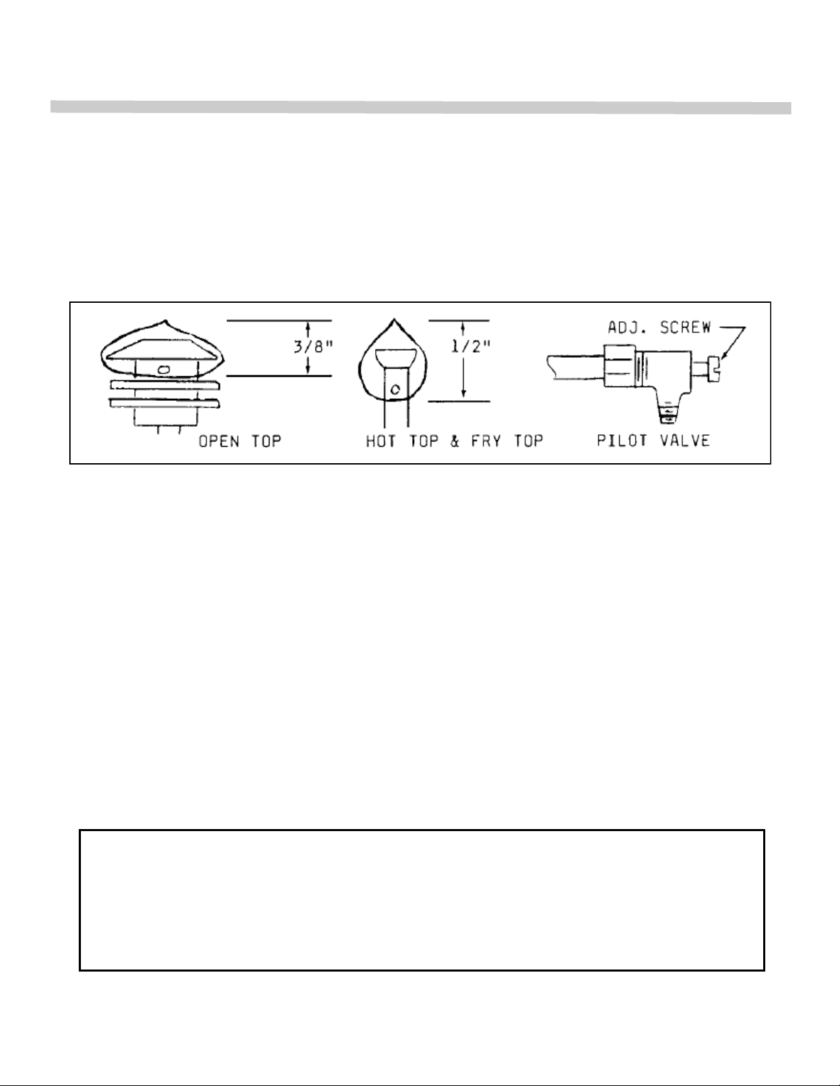
PILOT ADJUSTMENT—TOP BURNERS
OVEN TOP: The front and rear pilots are controlled by one valve. To adjust pilot, turn
adjusting screw counterclockwise to increase or clockwise to decrease pilot flame. Adjust flame to
a point where only a trace of yellow tip remains.
FRY TOP and HOT TOP: Each pilot is controlled by a pilot valve. Turn adjusting screw until
pilot flame is 1/2‖ high.
BURNER ADJUSTMENT
The efficiency of the range depends on a delicate balance between the supply of air and the
volume of gas so that complete combustion is achieved. Whenever this balance is disturbed, poor
operating characteristics occur.
The air supply is controlled by an air shutter on the front of the burner. The air shutter
openings should be increased until the flame on the burner begins to ―lift‖. The air shutter should
then be closed slightly and locked in place. A yellow streaming flame indicated insufficient air. This
condition can be corrected by increasing the air shutter opening.
FRY TOP AND OVEN THERMOSTATS
The by-pass (minimum burner flame) has been adjusted at the factory and should require
no further adjustment.
THE BY-PASS FLAME MUST BE RECHECKED WHEN PERFORMING CHECKOUT OF
RANGE PRIOR TO PLACING EQUIPMENT IN SERVICE. THE BY-PASS MUST BE SET
CAREFULLY AND ACCURATELY. REFER TO SERVICE SECTION OF THIS MANUAL
FOR PROPER PROCEDURE.
INSTALLATIONINSTALLATION
10
OPERATION
OPERATING INFORMATION FOR THE RANGE HAS BEEN PREPARED FOR USE
BY QUALIFIED AND/OR PROFESSIONAL OPERATING PERSONNEL.
CAUTION
DO NOT OBSTRUCT THE FLOW OF COMBUSTION AND VENTILATION AIR. KEEP
THE APPLIANCE AREA FREE AND CLEAR FROM COMBUSTIBLES.
GAS CONTROLS
Top Burners— Open Top, Hot Top and Manual Fry Top
Check that pilots are burning. Then rotate valve handles counterclockwise to full on, burner will
ignite automatically. Adjust flame height as desired. To shut down, rotate valve handle clockwise
to ―OFF‖ position.
Fry Top– Thermostat Controlled
Check that the pilot(s) are burning. Then push thermostat dial inward and rotate dial counter-
clockwise to maximum thermostat setting, burner(s) will ignite automatically. After ignition, turn
thermostat dial to desired setting. To shut down, rotate thermostat dial clockwise to ―OFF‖
position.
OVEN
A. Lighting
Turn thermostat knob to ―OFF‖ position and wait five (5) minutes.
1. Remove burner compartment cover and open pilot access door.
2. Press and hold red button in (Safety Pilot Valve) and apply lighted match to pilot burner.
3. After pilot burner ignites, continue to hold red button depressed for 30 for 45 seconds or until
pilot remains burning when button is released. If pilot goes out, repeat process.
IN THE EVENT A GAS ODOR IS DETECTED, SHUT DOWN UNITS AT MAIN
SHUT OFF VALVE AND CONTACT THE LOCAL GAS COMPANY OR GAS
SUPPLIER FOR SERVICE.
OPERATION

11
OPERATION
4. Close pilot access door and replace burner access panel.
5. Push thermostat dial inward and rotate dial counterclockwise to desired temperature setting.
6. Turn on fan. Fan should be on at all times during cooking operation.
7. IN THE EVENT OF PILOT FAILURE, ROTATE THERMOSTAT DIAL CLOCKWISE TO ―OFF‖
POSITION AND WAIT FIVE (5) MINUTES FOR UNBURNED GAS TO ESCAPE FROM
RANGE.
B. Shut Down
1. Stand By
a. Rotate thermostat dial clockwise to ―OFF‖ position.
b. Turn fan off.
2. Complete
a. Turn all gas valves to ―OFF‖ position.
b. Turn fan off.
c. Turn electrical service off or disconnect electrical supply cord from wall
receptacle.
C. Relighting
1. Rotate thermostat dial clockwise to ―OFF‖ position.
2. Wait five (5) minutes then follow lighting instructions in section ―A‖.
USING A CONVECTION OVEN
Your modern convection oven assures speedy cooking and quality performance. Its proper
use will result in gas energy conservation.
The convection oven is a different type of oven which offers many features and advantages
to the food service operation. The operation of the oven is not difficult to understand or control.
The convection oven is the sealed type whereby the combustion products are separated
from the air inside the oven. The heat is transferred through the oven surface into the cooking
cavity. The air inside the oven cavity is continuously recirculated over the heat source and the
product.
OPERATION
12
OPERATION
The moving air strips away the insulated layer of moisture on the products allowing heat to
penetrate faster for quicker baking and roasting. Due to these differences in the methods of
cooking in a convection oven, procedures and techniques may require some modification for
successful results. A general rule which will assist in better operation is cooking time will be less
and temperatures should be 25 to 75 degrees lower than those called for in standard recipes.
Oven Operation
1. Turn thermostat dial to desired temperature.
2. Limit preheat time to 15-20 minutes.
3. Place food in oven. Make sure pans do not touch each other, or the oven walls.
4. Do not cover racks with aluminum foil.
5. Load and unload quickly. Avoid frequent opening of doors.
6. Turn off when not in use.
SUGGESTIONS
There is no need to preheat an Open Top burner. Use full flame to start foods cooking quickly;
reduce flame to simmer foods. Regulate the burner so that flame tips just touch the bottom of
the utensil. Use lids on pots to keep heat in. Turn burner off when not in use.
Preheat Fry Top 10-15 minutes prior to use. Usually, a medium to low flame is adequate for
light frying. If Fry Top has a thermostat, use it to avoid wasting gas and for best results. During
slack periods, turn the burner down.
FOR CONVECTION OVEN COOKING, REDUCE TEMPERATURE 25 TO 75 DEGREES
FROM THOSE GIVEN IN STANDARD RECIPES.
TYPE OF FOOD REDUCTION IN REDUCTION IN
TEMPERATURE TIME
Baked Products
Cookies 25°F 1/4 to 1/3
Cakes & Quick Bread 50°F 1/4 to 1/3
Yeast Products 75°F 1/4 to 1/3
Casseroles 25°F 1/4 to 1/2
13
COOKING HINTS

14
COOKING HINTS
BAKING DIFFICULTIES & PROBABLE CAUSES
UNEVEN BAKES
1. Insufficient heat input.
2. Warped pans.
3. Warped oven racks.
4. Uneven loading of pan or pans.
5. Fan off.
6. Oven not level, causing dough to run to side or rear of pan.
SPOTTY PIE BOTTOMS
1. Overworked pastry.
SPOTTY BREAD
1. Overworked dough.
BURNED GOODS, CRIPPLES
1. Incorrect temperature.
2. Thermostat out of calibration.
3. Left in too long.
4. Improper scaling.
DRIED OUT GOODS
1. Too low temperature.
2. In oven too long.
3. Improper mix.
ALTERNATELY GOOD AND POOR RESULTS
1. Fan off and on.
2. Improper scaling and control of ingredients.
TOPS DARK, CENTER NOT DONE
1. Too high temperature
SIDE BURNING
1. Oven not level.
2. Uneven loading.
LACK OF UNIFORMITY—SAME PAN
1. Uneven loading in pans. (See uneven bakes)
2. Faulty pans.

15
COOKING HINTS
LACK OF SPRING
1. Overproofing.
2. Incorrect temperature.
CRACKED CAKES
1. Too high temperature.
2. Too fast cooling.
UNDERDONE PIE BOTTOMS
(Advisable to bake on cookie sheet)
1. Pastry too rich.
2. Pastry too thick.
3. Warped pie tins (when used on cookie sheet).
HEAVILY COLORED PIE RIMS
1. Air bubbles enclosed in pastry when crimped.
UNEVEN BAKED COOKIES
1. Not scaled properly.
2. Pans warped.

16
Care and Cleaning
The complete range should be given a periodic general cleaning. Lint and grease suspended in
the air tend to collect in air passages. Therefore, all flueways, air passages and openings, burner
ports, primary air openings, etc., should be periodically cleaned to prevent clogging.
Exterior
PAINTED SURFACE: Allow equipment to cool after use and wash with a mild detergent or soap
solution. Dry thoroughly with a clean cloth.
STAINLESS STEEL SURFACE: To remove normal dirt, grease, or product residue from stain-
less steel, use ordinary soap and water (with or without detergent) applied with a sponge or
cloth. Dry thoroughly with a clean cloth.
To remove grease and food splatter, or condensed vapors that have baked on the equipment,
apply cleanser to a damp cloth or sponge and rub cleanser on the metal in the direction of the
polish lines of metal. Rubbing cleanser as gently as possible in the direction of the polished lines
will not mar the finish of the stainless steel. NEVER RUB WITH A CIRCULAR MOTION. Soil
and burnt deposits which do not respond to the above procedures can usually be removed by
rubbing the surface with SCOTCH-BRITE scouring pads or STAINLESS scouring pads. DO NOT
USE ORDINARY STEEL WOOL as any particles left on the surface will rust and further spoil the
appearance of the finish. NEVER USE A WIRE BRUSH, STEEL SCOURING PADS (EXCEPT
STAINLESS), SCRAPER, FILE, OR OTHER STEEL TOOLS. Surfaces which are marred collect
dirt more rapidly and become more difficult to clean. Marring also increases the possibility of
corrosion attacking the surface.
TO REMOVE HEAT TINT: Darkened areas sometimes appear on stainless steel surfaces
where the area has been subjected to high heat. These darkened areas are caused by
thickening of the protective surface of the stainless steel and are not harmful. Heat tint can
normally be removed by the foregoing, but tint which does not respond to this procedure calls for
a vigorous scouring in the direction of the polish lines, using SCOTCH-BRITE scouring pads or a
STAINLESS scouring pad in combination with a powdered cleanser. Heat tint action may be
lessened by not applying or by reducing heat to equipment during slack periods.
MAINTENANCE MAINTENANCE
CAUTION
DISCONNECT POWER BEFORE CLEANING OR SERVICING. EACH
OVEN SECTION HAS A SEPARATE ELECTRICAL SUPPLY
CONNECTION.

17
MAINTENANCE
OPEN TOP SECTION
DAILY: After grates and burner bowls are cooked, soak in solution of sal soda or other grease
solvent. Thoroughly wash open top section with a damp cloth using a mild detergent soap. Rinse
with clean, damp cloth and dry thoroughly. Remove and clean drip pan(s) under burners.
WEEKLY: Brush burner head with a stiff wire brush and clean clogged ports with a stiff wire or ice
pick.
Excessive grease build up may be removed from burners by soaking in a solution of washing soda
or any good grease solvent. Dry burners by inverting on oven rack in a low temperature oven.
FRY TOP SECTION
DAILY: Use flat edge of spatula or metal scraper to keep surface free of encrusted material during
use, wipe frequently with heavy absorbent cloth. After griddle is cooled, polish with soft griddle
stone or a good grade grill pad. DO NOT SCRATCH. The griddle may be washed with warm water
and a cleanser. Water will not crack this griddle plate.
Empty grease container as often as necessary.
To oil the griddle, use hydrogenated shortening. Never use salad oils, margarine or butter, as
these shortenings cannot withstand temperatures greater than 300 degrees Fahrenheit.
HOT TOP SECTION
DAILY: Wipe top with heavy burlap or steel wool. Rub briskly until clean. The Hot Top plate may
be washed with warm water and a cleanser. Water will not crack this Hot Top plate.

18
MAINTENANCE
OVEN INTERIOR
Aluminized Steel — Top, Sides, and Back:
Porcelain Enamel— Bottom and Door Liner:
Wipe up spillovers while oven is hot. Wait until oven is cool for complete cleaning. Spray type oven
cleaners may be used. A mild abrasive nylon cleaning pad can be used for stubborn spillovers or
stains. After cleaning, rinse well with 1/4 cup of vinegar to 1 quart water solution to neutralize any
caustic residue of cleaning compound. Wipe dry.
ELECTRIC MOTOR
The electric motor has been specially manufactured for this blower application and should give
years of trouble free service under normal conditions.
This unit is supplied with permanently lubricated sealed bearings which require no additional
lubrication. A high temperature grease has been used to increase bearing life and should only be
replaced by an authorized service station.
The motor is of an open drip-proof type construction, and as such, care should be given to see that
the ventilation openings remain clear.
The motor is equipped with built-in automatic thermal overload protection to prevent damage from
overheating.
If problems do develop with the motor, contact your nearest authorized service station.
CAUTION!
Do not use wire brushes, steel wool, or caustic solutions such as spray type
cleaners, ammonia, lye, or soda ash. Damage to the aluminum coating will
result. USE ONLY CLEANERS THAT ARE RECOMMENDED FOR USE ON
ALUMINUM.
MAINTENANCE
CAUTION!
CARE SHOULD BE USED WHEN WASHING DOWN EQUIPMENT TO KEEP
WATER AND CLEANING SOLUTIONS OUT OF THE MOTOR OR DAMAGE WILL
OCCUR.
19
SERVICE
WHEN SERVICE IS NEEDED, CONTACT A LOCAL SERVICE COMPANY,
DEALER, OR FACTORY TO PERFORM MECHANICAL MAINTENANCE AND
REPAIRS. THESE INSTRUCTIONS ARE INTENDED FOR USE BY COMPETENT
SERVICE PERSONNEL.
CAUTION!
DISCONNECT POWER BEFORE DOING ANY SERVICE WORK. EACH SECTION
HAS SEPERATE ELECTRICAL SUPPLY CONNECTIONS. TURN OFF GAS
SUPPLY WHEN SERVICING GAS CONTROL SYSTEM.
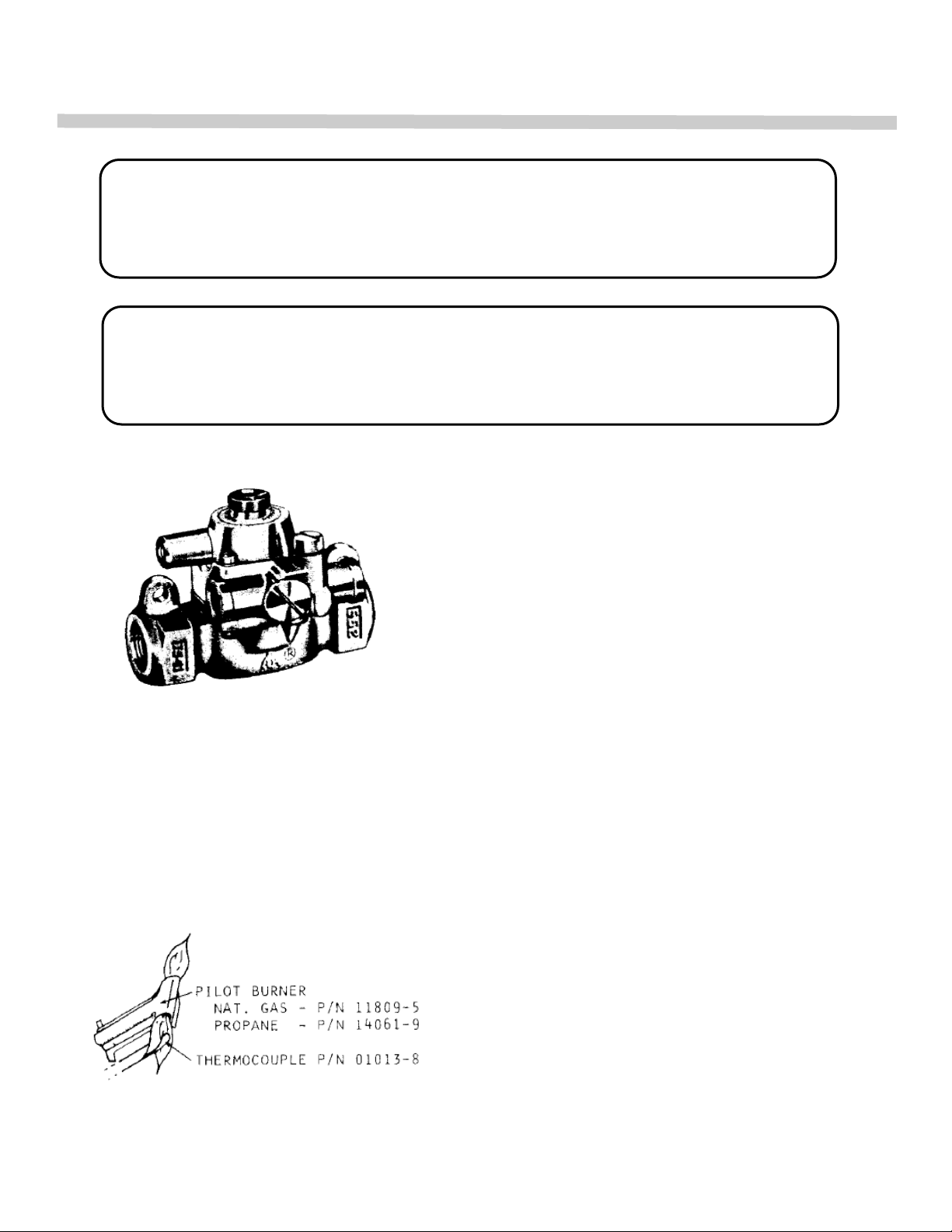
SAFETY PILOT VALVE
Model TS-11J IS AN AUTOMATIC 100% safety pilot
which provides complete gas shut off in event of pilot
failure. The safety valve is held closed by spring pres-
sure. When red button is pushed by hand, gas flows to
pilot. Pilot heats thermocouple creating a very small
amount of electricity. This energizes a magnetic coil
under red button and holds valve open, permitting gas
to flow to main burner and pilot with out holding pres-
sure on red button. In the event of pilot failure, the flow
of electricity will stop, and spring will stop flow of gas to
both pilot and oven burner.
PIEZO IGNITER
The PIEZO IGNITER creates an ignition spark at the pilot burner when the red button is de-
pressed until it clicks. The spark is generated at the tip of the OVEN ELECTRODE, which is posi-
tioned inside of the pilot burner hood. The spark jumps from the OVEN ELECTRODE to the
pilot burner hood, across the pilot gas exit.
OVEN PILOT BURNER
Pilot Service in the Event of Pilot Failure
1. If pilot flame burns yellow, clean pilot orifice and
pilot burner to insure a steady blue flame. The orifice
can be cleaned by washing in a solvent and/or blow-
ing out with air.
2. Flame must surround the thermocouple tip for ap-
proximately 1/2 inch.
SERVICE
20
SERVICE
OPEN CIRCUIT MV RANGE
NORMAL NOT LESS THAN
15-25 8
THERMOCOUPLE OUTPUT
If the closed circuit check shows thermocouple output is greater than 8 millivolts and pilot will not
remain lit when button is released, replace safety pilot magnet assembly.
3. Thermocouple lead connections must be tight, clean, and free of grease. The thermocouple nut
should be started and turned all the way by hand. An additional quarter turn with a small
wrench will be sufficient.
FRY TOP THERMOSTAT
The model BJ Robertshaw is a combination thermostat and gas valve. The gas is turned on
and the temperature setting made by a single rotation of the dial. The valve automatically locks
itself in the ―OFF‖ position. To use, push dial inward, rotate counterclockwise to the desired
temperature. To shut gas off, rotate clockwise to the ―OFF‖ position.
This thermostat is a precision instrument carefully made and properly calibrated (i.e. the dial is
properly set) at the factory to control temperatures accurately. It should control temperatures for
the proper cooking of food without recalibration. The calibration of the thermostat should not be
changed until considerable experience with cooking results has definitely proved that the
thermostat is not maintaining the proper temperature.
CAUTION!
OVERTIGHTENING MAY CAUSE DAMAGE TO THE THERMOCOUPLE
OR MAGNET AND IS UNNECESSARY SINCE THIS IS AN ELECTRIC
CONNECTION.
CAUTION!
THE RECALIBRATION SHOULD NOT BE MADE UNTIL THE BYPASS
(MINIMUM BURNER) FLAME HAS BEEN PROPERLY ADJUSTED.
SERVICE
Table of contents
Popular Convection Oven manuals by other brands


cecotec
cecotec BAKE&TOAST 2600 WHITE 4PIZZA instruction manual

Crofton
Crofton CFCO12W instructions

Fisher & Paykel
Fisher & Paykel OM60NDTX1 installation guide

Wolf
Wolf WKECX1 Specification sheet

Star Manufacturing
Star Manufacturing Holman CCOF-4 Specification sheet

Galloping Gourment
Galloping Gourment Perfection-Aire Cookbook & Instruction Manual


