the2Mic the2Micpro User manual
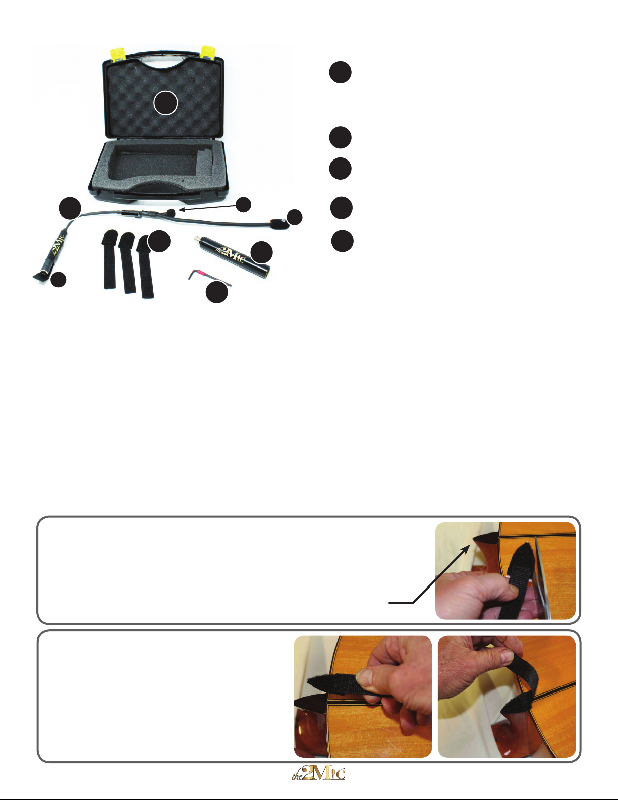
Standard the2MicPro™ components:
STEP 1: INSTALL THE VELCRO STRAP
2
1
2. Remove the plastic backing and apply
the velcro to the heelcap.
Note that the velcro hook strap can
be folded over to mate with the velcro loop.
is strap will be used to help secure the
gooseneck.
Durable Carry Case.
1
35
4
the2Micpro with 1/4” mono output jack.
(1A) Mic #1 on the short gooseneck
(1B) Mic #2 on the long gooseneck
(1C) 1/4” output jack (mono)
2
EPS-2 phantom power supply adapter.
1/4” input, balanced XLR output.
3
4
Velcro Straps with adhesive attachments for
heelcap of the guitar (3 provided).
5
3/32” Hex Wrench (2.5mm).
Also needed but not supplied:
-A standard mono guitar cable with one
right angle (90°) plug.
-A standard XLR mic cable.
1B
1C
1A
Important Product Note:
e 2Micpro™, while easily installed or removed, is designed to remain indenitely installed on a guitar.
With the2Micpro™ installed, the guitar should t easily and securely into most travel cases. is eliminates the need
to remove the2Micpro™ aer use.
If the 1/4” output jack extends too far beyond the back of the guitar, the jack may contact the bottom of the
guitar case when the guitar is stored. If the output jack does not extend enough beyond the back of the guitar, the
right angle plug of the output cable may not fully insert into the jack.
e 2Micpro™ has the capability to adjust in length to accommodate various guitar body dimensions. is
ensures that the 1/4” output jack can be set to extend beyond the back of the guitar to the proper distance. is will
be explained in greater detail on page 2 (step 3).
1. Use scissors to trim the adhesive backed portion of the velcro
strap to match the outline of the heelcap.
Product Manual for the2Micpro™ 1 of 4
Heelcap

STEP 2: INSTALL THE GOOSENECK
1Insert the2Mic gooseneck into the guitar through the bass
edge of the soundhole (although pictured without, the strings
can remain on guitar). Fit the hook over the edge of the
soundhole.
Mic #1 (short gooseneck) is naturally located near the best
position - just below the strings, and pointing towards the interior
of the guitar.
Mic #2 (long gooseneck) should be positioned in the center
of the guitar body, approximately underneath the bridge, and with
the mic element pointed towards the soundboard. (white dot on the
windscreen indicates the active direction of the mic).
NOTICE - To provide the best possible shock mounting, the microphones
are very lightly attached to the gooseneck. Do not handle the windscreen
covering the mic elements. Adjust the position of the mic by holding the
gooseneck behind the mic and bending only the gooseneck.
Outside the soundhole the gooseneck is positioned
alongside the fretboard and bent down the side of the
guitar toward the heelcap. There should be a sharp bend
where the top and side of the guitar meet. The output jack at
the end of the gooseneck will rest against the heel.
Product Manual for the2Micpro™ 2 of 4
2
Adjust the length of the output jack so that the end of
the output jack extends 1/2” (13mm) beyond the back of
the guitar, then tighten the set screw (turn the 3/32” [2.5mm]
Hex Wrench clockwise to tighten). If the jack does not extend
sufficiently beyond the back of the guitar, the right angle (90°)
plug of the output cable may not fully engage the jack.
3
Pull the output jack against the heel with the attached
velcro strap and secure it the heelcap velcro. Plug a right
angle cable into the jack. Secure the right angle cable
with the heelcap velcro strap.
Note: the width and length of the velcro straps may be
trimmed with scissors to adjust for various heelcap sizes.
With the volume on your powered speaker or mixer turned
down, plug the other end of the right angle cable into the 1/4”
jack of the EPS-2. Plug an XLR cable into the output of the
EPS-2. Plug the other end of the XLR cable into a channel of
your powered speaker or mixer and turn on phantom power
(see page 4 for signal path).
4

Photo #1 shows an interior view of the recommended positions for
the mics on the gooseneck.
Mic#1 (short gooseneck) points across the soundhole.
Mic #2 (long gooseneck) is positioned under the center of the
soundboard beneath the bridge, and located approximately 1.5 inches
(40 mm) below the soundboard.
Most classical & amenco guitars will sound excellent with
these mic positions, but the sound quality of some guitars may be
improved by further adjusting the positions of the mics.
More tips on Mic positioning - ere is no single location in or outside of a guitar where the complete sound of the
instrument can be recorded, which explains why having 2 properly phased internal mics helps to achieve the best sound
quality and without feedback. e soundhole acts as a natural mixer, and Mic #1 records most all of the frequencies produced
by the guitar. Some frequencies at the soundhole may be too strong or weak, and careful positioning of Mic #2 on the long
gooseneck can help to balance the overall sound. ere are 3 basic methods, described further below, to reposition Mic #1
(lon g gooseneck) to adjust the tone quality captured by the2Micpro™.
Mic #1 points across
the soundhole
Drawing #3
Mic #2 is positioned under the
center of the bridge, approx.
1.5” below the soundboard. e
white dot on the windscreen
indicates the active direction of
the mic
POSITIONING THE MICS
Product Manual for the2Micpro™ 3 of 4
Drawing #1
1. Change the mic location inside the guitar. (Drawing #1) is is the
most simple justment can be made while the gooseneck assembly is installed
by reaching one or two ngers past the strings and through the soundhole to
grab onto and adjust the long gooseneck.
2. Change the distance the mic is positioned from the soundboard.
(Drawing #2) Mic #2 can be as close as 1/2 inch (12 mm) or as distant
as 42 mm (2 inches). A mic position close to the soundboard will help
to increase specic frequencies while dimishing the overall frequency
blend, and is oen good for eliminating a wolf tone. Positioning Mic
#2 further away from the soundboard will capture a greater
spectrum of the frequency response.
3. Change the angle for how the mic points towards the
soundboard. (Drawing #3). Mic #2 can point directly upwards
towards the soundboard, or can be placed anwhere along a 180 degree arc.
At the 0° or 180° degree position, Mic #2 will be pointing towards the side
(rib) of the guitar. An angle slightly o 90° center (80° or 100°) is usually
best overall, but anywhere on this 180° arc has yielded excellent results in
dierent guitars.
Drawing #2
Photo #1
Photo #2
Common adjustments: Mic #1 (short gooseneck) can be adjusted to
point more towards the interior of the guitar. is may help to reduce
nger and nail noise from the strings. Mic #2 (long gooseneck) can be
swung in an arc across the soundboard towards the treble or bass side
(seedrawing#1below). ismayhelptoreduceexcessivebassresponse
or calm down an annoying wolf tone. e white dot on the windscreen
of Mic #2 indicates its active direction. More information about how
to adjust this mic is below, and on our website: www.the2Mic.com
Photo #2: shows reaching in past the strings and through the
soundhole to grab the long gooseneck to make adjustments. Note
how there is no contact with Mic #1 (short gooseneck). e ngers
only grab the base of the long gooseneck for Mic #2.

For the best possible sound use full range loudspeakers. Many acoustic guitar ampliers are designed
primarily for use with pickups. While these “acoustic amps” may sound good with the2Micpro™, it will not compare
to that of high quality powered loudspeaker mounted on a speaker stand.
A full PA system with a skilled audio engineer at the controls is the best option for the highest quality sound
during performances. For amplication on stage, (monitors) we recommend using a single powered speaker
mounted behind the guitarist. For recommendations of specic brands of powered speakers, please visit:
www.the2Mic.com.
SIGNAL CHAIN RECOMMENDATIONS
- Element: Electret condenser
- Frequency response: 50 - 16K Hz
- Pattern - cardiod uni-directional
- Output: 500 ohm, balanced (XLR)
- Sensitivity -45 dB
- Max. SPL - 131 dB
Microphone specications:
Donnells-MiniFlex™ - the2Mic™ • P.O. Box 433 • Greenville CA • 95947 • Tel. (530) 284-1689
www.the2mic.com, or miniexmic.com • Email: sales@miniexmic.com
Patented: 5,010,803, 6,441,292 & 8,035,025 other patents pending
Optional TourMic wireless™ - e2Micpro™ has been designed to receive an optional wireless transmitter as part
of theTourMic wireless™ system. e wireless transmitter provides low voltage phantom power to the2Micpro™ and
eliminates the need for the EPS-2. Visit www.the2Mic.com, or TourMic wireless for more information.
Mono cable with right angle (90°) plug
(not supplied) connects the output jack of
the2Micpro to the EPS-2 power supply.
EPS-2 Power Supply
(requires phantom
power)
Standard XLR
Cable
(not supplied)
Powered
Speaker
(not supplied)
P.A. Mixer
(not supplied)
or
- Phantom Power capacity: 9 - 48 volt
- Input: 1/4” mono
- Output: 500 ohm, balanced (XLR)
EPS-2 specications:
Product Manual for the2Micpro™ 4 of 4
SPECIFICATIONS
Your powered speaker or mixer
must be able provide phantom
power to the EPS-2.
Table of contents


