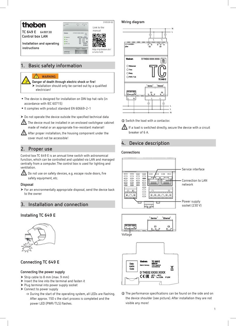
Theben EM LAN top2 User manual

EM LAN top2
LAN module
649 0 900
310 335
Designated use
The LAN module EM LAN top2 links the Ethernet LAN network
with the DATA bus interface of the 365 day time switch, i. e. the
TR top2 365 day time switches are addressed by a PC via an
there LAN network (direct remote control); can be operated in
local network and via VPN tunnel.
The LAN module enables status information, switching pro-
grams and device settings to be transmitted to/from the con-
nected time switches. LAN top2 software is required to operate
the EM LAN top2 LAN module. This is available for downloaded
at www.theben.de.
Installing the EM LAN top2 LAN module
• The EM LAN top2 LAN module is designed to be installed
on DIN hat rails (in accordance with EN 60715).
• Strong interference fields can cause faults.
Do not install EM LAN top2 LAN module
near inductive consumers.
Lay separate mains connection.
Shield inductive consumer.
Press reset > key for 3 secs
The current IP address is deleted.
The EM LAN top2 LAN module is set to "automatically
obtain address" (DHCP).
Reset button
EM LAN top2 and LAN top2 software
Precondition: EM LAN top2 LAN module, LAN top2 software,
LAN network and DHCP server must be available.
Only use 1 EM LAN top2 LAN module per DATA bus.
Up to 4 timers can be connected to 1 EM LAN top2 LAN
module via DATA bus.
DATA bus cable length max.100 m.
Setting up the EM LAN top2 LAN module
The EM LAN top2 LAN module is supplied without a fixed
IP address and is configured as a DHCP client.
1. In network with DHCP server
Use LAN top2 software to let the EM LAN top2 module
search and select.
2. Without DHCP server
Use a LAN cable to connect the EM LAN top2 module with
the PC.
Set PC to “Automatically acquire address” (PC does not have
IP address).
PC and EM LAN top2 module automatically receive an
address from a set sub-network.
Use LAN top2 software to select the EM LAN top2 module
and allocate fixed IP address.
Reset network settings on PC.
3. If you have allocated a fixed IP address and want to
set the EM LAN top2 module to DHCP …
Press reset > button for 3 secs (green LEDs go out). The EM
LAN top2 module is reset to factory setting, no longer has an
IP address and acts as a DHCP client.
Safety advice
Danger of death through electric shock or
fire!
Installation should only be carried out by a
qualified electrician!
WARNING
L N
EM LAN top2
Data +
-
2,5mm2
0,5mm -
2
230V~
50-60Hz
8mm
Connecting the EM LAN top2 LAN module
Data
N
L
L N
TR 64x top2
RC
Connect cable
Strip cable by 8 mm (max. 9 mm) .
Insert cable at 45° in the open terminal
(2 cables per terminal position possible).
Only with flexible wires: To open the spring screwless
terminal, press screwdriver downwards.
1

LAN top2 software
The LAN top2 software is available for download to
www.theben.de/produkt/6490900. In addition to functional
description, technical details, the software is available under
Downloads.
Starting LAN top2 software.
The home page opens with the following window:
1. How can you find LAN modules?
– automatically in the LAN: The LAN top2 software searches
for the connected LAN modules and lists them.
– by entering an IP by hand: The IP address of a LAN module
can be entered directly in a separate window.
– by reading IPs from a file: A file in text format is selected
that lists the IP addresses.
2. Response at restart
– show this window again
– execute last choice
Make selection.
2
A list of IP addresses then appears (see fig.).
Select IP address.
You can change the IP addresses and the name of the EM LAN
top2 module.
Press Change IP address/name enter new IP address/
new name and press OK.
Press Connect.
• Cable types for DATA bus (max.100 m): Sheathed cable:
NYM (3 x 1.5 mm2); MSR cable:
PYCYM, YCY (2 x 2 x 0.8 mm2)
telephone cable: J-Y(St)Y (2 x 2 x 0.8 mm2)
Bell wire: YR
• Power supply at DATA bus: 50 mA
(maximum current at DATA bus:
500 mA)
• Mode of operation: Type 2 in accordance with EN 60730-1
• Pollution degree: 2
Technical data
• Operating voltage: 230 V~, +10 %/-15 %
• Frequency: 50-60 Hz
• Power consumption: typically 7.5 VA
• DATA bus: Bus voltage: 15 V DC, low
voltage in protection class III (SELV)
• Permissible ambient temperature: –30 °C ... +50 °C
• Protection class: II in accordance with EN 60730-1 with
designated installation
• Protection rating: IP 20 in accordance with EN 60529

The status information from the connected time switches ap-
pears in the Monitor register; e.g. Date/time,
upgrade module, channel, PIN, On switching times etc.
(see fig.).
Press Refresh. The data is requested from the time
switch.
Changing update time
You can change the upgrade time (2 s to 10 min) in the
Options menu under Refresh time.
3
The Direct commands register allows you to directly perform
actions for each channel (continuous ON, continuous OFF, man-
ual ON, manual OFF, start timer, activate special programmes
and reset the operating hours counter).
You can also change the date/time and enter or delete PIN
(see fig.).
Select action and press Send.
The connected time switches appear
(e.g. TR 644 top2 RC) (see fig.).
Select desired time switch.
You can also change the name of the time switch here. The new
name is only stored in the LAN software on the PC and not and
not in the EM LAN top2 module.
Press Change name, enter new name and
press OK.
Press Connect.
The operator interface appears with remote access to selected
time switches. It is operated via 3 registers:
1. Monitor – Status information from the time switch
2. Direct commands – Access to the time switch
3. Communication – Program and settings

The following points are accessed via the Menu bar:
• File
– Restart program
The program is restarted and the EM LAN top2 modules are –
depending on the search setting – displayed again.
– Search clock(s)
You can select another timer here if several time switches are
connected to an EM LAN top2 module.
– Exit
The program ends.
• Options
– Language
You can select the program language here. This language is
retained even after a restart.
– Refresh time
The length of time the data is read from the time switch can be
set between 10 secs and 5 mins.
A file selection list appears, allowing you to select or enter the
desired file (.ot2).
You can input, display and change the received .ot2 file using
the OBELISK top2 software.
4
Service address
Theben AG
Hohenbergstr. 32
72401 Haigerloch
GERMANY
Telephone +49 (0) 74 74 6 92 0
Fax +49 (0) 74 74/6 92-150
Hotline
Telephone +49 (0) 74 74 6 92 -369
Fax +49 (0) 74 74/6 92-207
Addresses, telephone numbers etc.
www.theben.de
You can send and receive .ot2 files for the OBELISK top2 soft-
ware in the Communication register (see fig.).
Options:
– only send program
– send program and settings
– receive program and settings
Select action and press Send or Receive.
– How to search
The way EM LAN top2 modules are searched for can be set.
If the setting is changed, the program restarts to accept the
change and start a new search.
• Help
– About ...
Here you can find out about the program
(version number etc.).
Other Theben Control Unit manuals
Popular Control Unit manuals by other brands
Power-Tronics
Power-Tronics SEM100A manual

Ban Seok
Ban Seok BV-300T instruction manual
Alfalaval
Alfalaval Unique SSV Series instruction manual
ITS Telecom
ITS Telecom EKSELANS IPC 24 user manual
Qcells
Qcells Q.PEAK DUO-G10.X Series Operating and maintenance instructions
SimCom
SimCom SIM5218E Hardware design
