ITS Telecom EKSELANS IPC 24 User manual

ITS Partner O.B.S S.L · Av. Cerdanyola 79-81 Local C
08172 Sant Cugat del Vallés · Barcelona (Spain)
Phone: +34935839543 · info@ek.plus · www.ek.plus
USER MANUAL IPC 24/IPC AC
V03
TABLE OF CONTENTS
Installation .................................................................................................................................................................................................................................... 4
Packaging and accessories ..................................................................................................................................................................................... 4
Hardware features........................................................................................................................................................................................................... 5
IPC 24/IPC AC Installation......................................................................................................................................................................................... 7
IPC 24/IPC AC Connection....................................................................................................................................................................................... 7
Operating the IPC 24/IPA AC.......................................................................................................................................................................................8
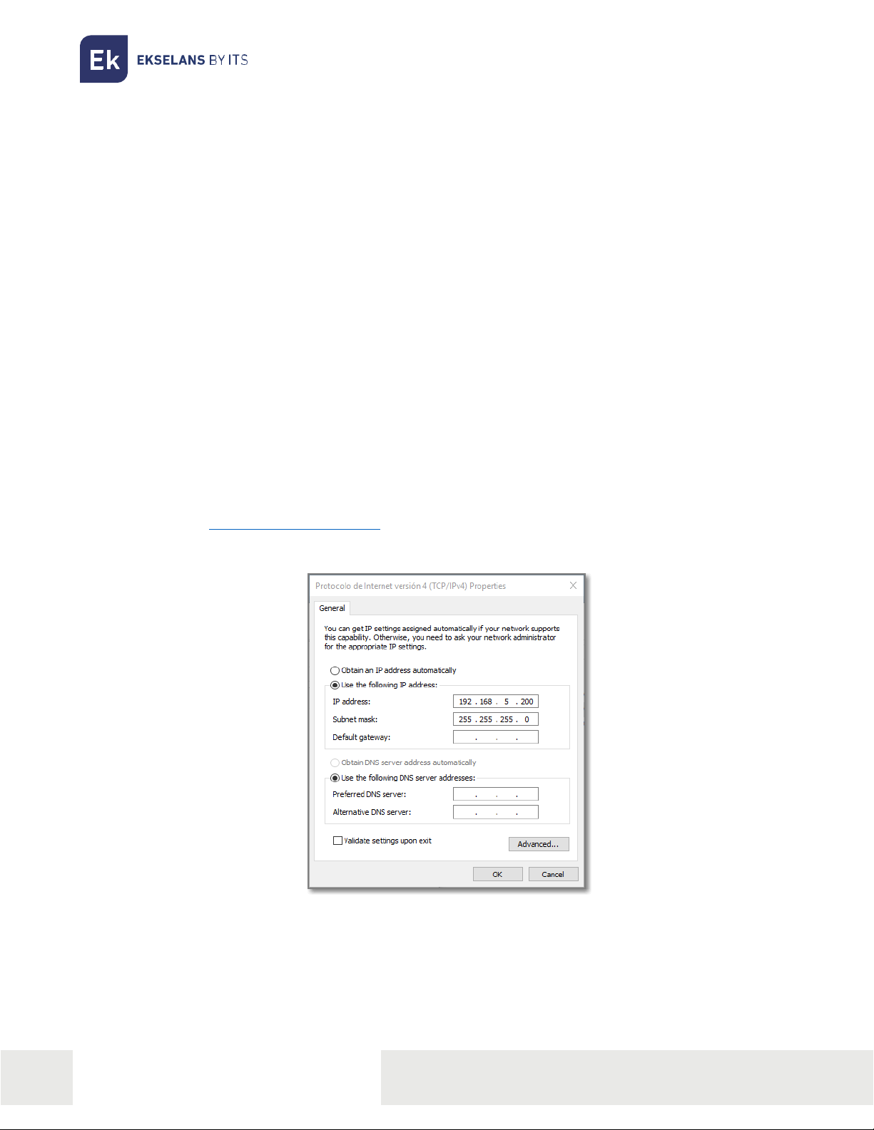
Preparation IPC 24/ IPC AC for web management.............................................................................................................................8
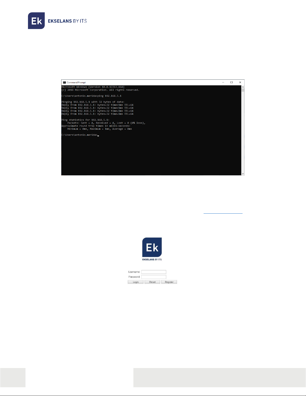
Web Management Access ......................................................................................................................................................................................9
Web management interface......................................................................................................................................................................................10
Introduction .........................................................................................................................................................................................................................10
Main menu............................................................................................................................................................................................................................10
Status...............................................................................................................................................................................................................................................11
Device information .........................................................................................................................................................................................................11
WAN Information.............................................................................................................................................................................................................11
LAN Information. ............................................................................................................................................................................................................. 12
Remote Management Status (ONLY IN IPC 24)................................................................................................................................... 12
NAT Status ...........................................................................................................................................................................................................................13
Network........................................................................................................................................................................................................................................14
Broadband Setup ...........................................................................................................................................................................................................14
LAN Settings.......................................................................................................................................................................................................................16
QoS .............................................................................................................................................................................................................................................18
WLAN2 (ONLY IN IPC AC) ......................................................................................................................................................................................19
WLAN......................................................................................................................................................................................................................................20
Remote Control (ONLY IN IPC 24)....................................................................................................................................................................21
Time Synchronisation ................................................................................................................................................................................................. 21
Security.........................................................................................................................................................................................................................................22

ITS Partner O.B.S S.L · Av. Cerdanyola 79-81 Local C
08172 Sant Cugat del Vallés · Barcelona (Spain)
Phone: +34935839543 · info@ek.plus · www.ek.plus
USER MANUAL IPC 24/IPC AC
Firewall....................................................................................................................................................................................................................................22
URL Filtering.......................................................................................................................................................................................................................22
MAC Filtering......................................................................................................................................................................................................................23
IP Filtering/Port Filter .................................................................................................................................................................................................23
Remote Web Management ................................................................................................................................................................................. 24
Proto Filters ........................................................................................................................................................................................................................ 24
Service.......................................................................................................................................................................................................................................... 25
DDNS ....................................................................................................................................................................................................................................... 25
Advance NAT.................................................................................................................................................................................................................... 25
Port Forwarding .............................................................................................................................................................................................................. 26
IGMP ......................................................................................................................................................................................................................................... 26
System ......................................................................................................................................................................................................................................... 27
Administration................................................................................................................................................................................................................... 27
Backup /Flash Firmware........................................................................................................................................................................................ 27
Reboot .................................................................................................................................................................................................................................... 28
Diagnosis............................................................................................................................................................................................................................... 28
Language ............................................................................................................................................................................................................................. 29
Installation Examples.......................................................................................................................................................................................................30
Characteristics ........................................................................................................................................................................................................................31

ITS Partner O.B.S S.L · Av. Cerdanyola 79-81 Local C
08172 Sant Cugat del Vallés · Barcelona (Spain)
Phone: +34935839543 · info@ek.plus · www.ek.plus
4
USER MANUAL IPC 24/IPC AC
Installation
The coaxial internet user unit, IPC 24 and IPC AC model, enables performing a fast and secure
internet installation via coaxial cable in combination with the main header-end unit, IPC-M300
model.
•IPC 24 or IPC AC packaging and accessories
•IPC 24 or IPC AC hardware features
•IPC 24 or IPC AC installation
•IPC 24 or IPC AC connection
Packaging and accessories
In the IPC packaging, in addition to the manual, the following components are included:
User unit
Ethernet Cable
Power supply unit

ITS Partner O.B.S S.L · Av. Cerdanyola 79-81 Local C
08172 Sant Cugat del Vallés · Barcelona (Spain)
Phone: +34935839543 · info@ek.plus · www.ek.plus
5
USER MANUAL IPC 24/IPC AC
Hardware features
Rear panel
IPC 24 IPC AC
•CABLE: Radio frequency signal input.
•TV: Radio frequency signal output.
•Ethernet: LAN1 -LAN4: Ethernet LAN ports to connect a PC directly to the equipment. It can
function in router mode.
•DC 12V: Power supply connector
•ON/OFF: On/off button.
•Reset: Reset button.
•Antenna: 1 Wi-Fi antenna in the IPC 24 and 2 antennas in the IPC AC.
•USB: USB Port ONLY IN IPC AC

ITS Partner O.B.S S.L · Av. Cerdanyola 79-81 Local C
08172 Sant Cugat del Vallés · Barcelona (Spain)
Phone: +34935839543 · info@ek.plus · www.ek.plus
6
USER MANUAL IPC 24/IPC AC
Front panel
IPC 24 IPC AC
The device has the following status LEDs:
IPC 24
•EOC: (Ethernet Over Coaxial): If green, the device is functioning correctly.
•CAB: If green with slight flickering, it is functioning correctly. Off, the device is switched off or
there is no communication with the head-end device.
•LAN1-4: If green, the LAN port has established an Ethernet connection with another device
(for example, a PC). If flashing green, it is in data transfer or data reception process mode. Off,
the device is switched off or there is no Ethernet connection with another device.
•WIFI: If green it is working correctly. Off, the device is switched off or there is no established
Wi-Fi connection.
•POWER: If green, it will indicate that the equipment is connected to the power supply and is
functioning correctly.
IPC AC
•EOC: (Ethernet Over Coaxial): If green, the device is functioning correctly.
•CAB: If green with slight flickering, it is functioning correctly. Off, the device is switched off or
there is no communication with the head-end device.
•LAN1-4: If green, the LAN port has established an Ethernet connection with another device
(for example, a PC). If flashing green, it is in data transfer or data reception process mode. Off,
the device is switched off or there is no Ethernet connection with another device.
•WIFI: If green it is working correctly. Off, the device is switched off or there is no established
Wi-Fi connection.
•POWER: If green/red with slight flickering, it will indicate that the equipment is connected to
the power supply and is functioning correctly.

ITS Partner O.B.S S.L · Av. Cerdanyola 79-81 Local C
08172 Sant Cugat del Vallés · Barcelona (Spain)
Phone: +34935839543 · info@ek.plus · www.ek.plus
7
USER MANUAL IPC 24/IPC AC
IPC 24/IPC AC Installation
The user unit enables accessing the internet, either through a Wi-Fi connection or via connection to a
PC to one of the LAN ports of the equipment.
It is important to bear in mind that the range of the Wi-Fi network will depend on the location of this user
unit. For best results, a series of recommendations is specified below in this regard:
1. Locate the IPC in the area/room where computers, tablets are located. The connection will
improve if it is in the line of sight of this IPC user unit.
2. Attempt to locate the equipment far away from possible sources of interference, such as
fans, Wireless security systems, microwaves, 2.4 GHz transmitters or cordless telephone
base stations.
3. Likewise it is recommended to keep the equipment away from metal surfaces.
IPC 24/IPC AC Connection
To connect this user unit, follow the steps below:
1. Connect the LAN port to a device (for example, a PC).
2. Connect the RF IN connector to the coaxial cable from the distribution network, which will
be connected to the IPC-M300 head-end device.
3. Run power to the device through the supplied power supply.
4. Press the On/Off button on the rear panel to put into operation the IPC. The LED will flash
green/red.

ITS Partner O.B.S S.L · Av. Cerdanyola 79-81 Local C
08172 Sant Cugat del Vallés · Barcelona (Spain)
Phone: +34935839543 · info@ek.plus · www.ek.plus
8
USER MANUAL IPC 24/IPC AC
Operating the IPC 24/IPA AC
Accessing the IPC 24/IPC AC slave device
This chapter explains how to access and configure the IPC 24 and IPC AC slave after completing the
wiring set up procedure as explained in the previous chapter.
This chapter includes the following sections:
•Configuration preparation.
•Slave access..
Prepare IPC 24/ IPC AC for web management
Prior to accessing the IPC it is important to verify that the connection between the equipment and PC
is correct. It is recommended to follow the steps below
1. Configuration of the IP address of the PC to 192.168.5.X (2 ~ 254), subnet mask 255.255.255.0.
In order to become easy the configuration EK have the application Ek NET Adapter, you will
be able to configure the network adapter easily. You can download from
https:https://ek.plus/software/ you will find a new section "EK NET ADAPTER".

ITS Partner O.B.S S.L · Av. Cerdanyola 79-81 Local C
08172 Sant Cugat del Vallés · Barcelona (Spain)
Phone: +34935839543 · info@ek.plus · www.ek.plus
9
USER MANUAL IPC 24/IPC AC
2. Perform a “ping” to the IPC's IP address (by default 192.168.5.1). If the PC receives a correct
response to the ping command, this will mean that the connection between the PC and the
IPC is correct.
Web Management Access
1. Open an internet browser and enter the following IP address: http://192.168.5.1. By clicking
“Enter” will appear the login screen for the IPC 24/IPC AC.
2. The credentials to access as an administrator are: Username: ekselans Password: ek.plus.
3.
Having done so, press Enter to access the device management
.
Note: it is possible to change the password from the web management interface.

ITS Partner O.B.S S.L · Av. Cerdanyola 79-81 Local C
08172 Sant Cugat del Vallés · Barcelona (Spain)
Phone: +34935839543 · info@ek.plus · www.ek.plus
10
USER MANUAL IPC 24/IPC AC
Web management interface
The web management interface will allow for a quick configuration of different functions of the IPCs.
Introduction
The interface consists of three areas as shown in the previous image:
1. Main menu area
2. Sub area menu
3. Area to show the results.
Main menu
•Status: Device information, WAN Information, LAN Information, Remote Management Status
(ONLY IN IPC 24), NAT Status
•Network: Broadband Setup, LAN Settings, QoS, WLAN 2 (ONLY IN IPC AC), WLAN, Remote
Control (ONLY IN IPC 24), Time Synchronisation
•Security: Firewall, URL Filtering, MAC Filtering, IP/Port Filter, Remote Web Management,
Proto Filters.
•Services: DDNS, Advance NAT, Port Forwarding, IGMP.
•System: Administration, Backup/Flash Firmware, Reboot, Language.

ITS Partner O.B.S S.L · Av. Cerdanyola 79-81 Local C
08172 Sant Cugat del Vallés · Barcelona (Spain)
Phone: +34935839543 · info@ek.plus · www.ek.plus
11
USER MANUAL IPC 24/IPC AC
Status
The “Status” section includes submenus which displays different WAN and LAN connection values.
Device information
Click on the “Device information” section in order to access the following screen:
The model, functionality of the model in question, hardware version and software version will be
displayed.
WAN Information
The menu will display the following network-related information:
The page will display the status of the WAN connection. Displays the name of the current WAN
connection, connection type, connection status, default gateway, IP address obtained, subnet mask,
preferred DNS1 and DNS2.
It will likewise display the connection values with the head-end, such as: attenuation, entry/exit, and
noise levels.

ITS Partner O.B.S S.L · Av. Cerdanyola 79-81 Local C
08172 Sant Cugat del Vallés · Barcelona (Spain)
Phone: +34935839543 · info@ek.plus · www.ek.plus
12
USER MANUAL IPC 24/IPC AC
LAN Information.
It will display different information such as Wi-Fi status, errors and packets sent and received from same,
as well as the SSID status and encryption.
It will likewise display information as regards the LAN, the MAC of the slave or in the event of having a
device connected to its IP and the errors in the packets sent and received.
Remote Management Status (ONLY IN IPC 24)
Displays the remote management status.

ITS Partner O.B.S S.L · Av. Cerdanyola 79-81 Local C
08172 Sant Cugat del Vallés · Barcelona (Spain)
Phone: +34935839543 · info@ek.plus · www.ek.plus
14
USER MANUAL IPC 24/IPC AC
Network
The operating parameters of both the WAN, LAN or WLAN (Wi-Fi) can be configured and managed
from this menu.
Broadband Setup
The Network is configured by default. A new network can be changed, deleted or added. Different
WAN connections can be configured to offer various services to users.
In the event of changing or creating a new network, the following options are specified below:
Through this option, the WAN network settings are made. The WAN connection can function under
“route” mode or “bridge” mode. A LAN or Wi-Fi port can be connected in the WAN connection in the
Bind Port component.

ITS Partner O.B.S S.L · Av. Cerdanyola 79-81 Local C
08172 Sant Cugat del Vallés · Barcelona (Spain)
Phone: +34935839543 · info@ek.plus · www.ek.plus
15
USER MANUAL IPC 24/IPC AC
•VLAN ID: A number to the enabled VLAN can be assigned.
•802.1p: A priority to the VLAN, with 1 being the lowest and 7 highest is assigned.
•INTERNET NAME:
oTR069: The connection which is used for TR069.
oINTERNET: The connection is used for INTERNET, and does not withstand TR069.
oVOIP: CONNECTIONS AND USES FOR IP Voice
oINTERNTET_VOIP: The connection is used for INTERNET and VOIP.
oTR069_INTERNET: The connection is used for INTERNET and TR069.
oOther: For other options.
•Service mode:
oRoute: When the connection is established in Router mode, the WAN IP can be obtained
in three ways: DHCP, static or PPPoE. It is the default mode.
oBridge: It does not manage the IP, operates in a transparent manner by acquiring the
DHCP from another router. By acting transparently, everything will remain within the
network of the router which provides the service. If this operating mode is selected, the
PC or any other device will obtain the IP address of a higher layer device after
connection.
•ENABLE NAT: Enable/disable NAT in the connection.
•LINK Type:
oDHCP: Acquires a dynamic IP. And in the event of choosing the DHCP, the router will
obtain the address IP automatically from a higher-layer device.
oStatic IP: An IP is manually assigned.

ITS Partner O.B.S S.L · Av. Cerdanyola 79-81 Local C
08172 Sant Cugat del Vallés · Barcelona (Spain)
Phone: +34935839543 · info@ek.plus · www.ek.plus
16
USER MANUAL IPC 24/IPC AC
oPPPoE: Acquiring an IP via PPP protocol, a username and password will be assigned.
•Bind Port: Assignment of a door with the WAN service. The default WAN connection for all
doors is in Router mode. If a new WAN connection is chosen in Bridge mode, a Router mode
door can be assigned/unassigned. Different WAN connections can be configured to offer
several services to users.
Note: all doors are defined by default in Router mode. If a connection is established in Bridge mode, the
chosen door will be disconnected from the WAN. The WAN connection will be shared with all doors
specified in router mode except those defined in Bridge mode.
It is necessary to select a connection type in the WAN connection configuration. And as mentioned
earlier, one of three modes can be selected: static, DHCP and PPPoE depending on the application.
LAN Settings
This menu enables the configuration of the IP services of the LAN network, such as the DHCP.
The IPCs are preconfigured in router mode, to use private IP addresses in the section of the LAN, and
to act as a DHCP server. The default configuration of the LAN router is:
•IP LAN Address: 192.168.5.1
•Subnet mask: 255.255.255.0
These addresses are part of the range of private addresses for use in private networks and are available
for most applications. If the network on which the IPC will be installed requires a different IP address
system, it can be changed in the “LAN Settings” menu as shown in the following image.

ITS Partner O.B.S S.L · Av. Cerdanyola 79-81 Local C
08172 Sant Cugat del Vallés · Barcelona (Spain)
Phone: +34935839543 · info@ek.plus · www.ek.plus
17
USER MANUAL IPC 24/IPC AC
Note 1: In the event of changing the LAN IP addresses on the router while it is connected through a
browser, the router will be disconnected. It will then be necessary to open a new connection using the
new IP address and to enter once again.
By default the IPC acts as a DHCP server. It assigns an IP, DNS server and the default Gateway to all PCs
connected to the LAN network. The default IP address (192.168.5.1) is also the Gateway address. The IPC
will assign the IP addresses to all connected PCs, selecting these addresses from a range of addresses
specified in the “LAN Settings” screen.
DNS: Server which enables access to websites via their names. If the internet provider requires specific
information on these servers, select this option and enter the IP addresses of the DNS servers.
Note 2: DHCP is the abbreviation for Dynamic Host Configuration Protocol, which automatically assigns
IP addresses, subnet mask and default gateway to LAN users.

ITS Partner O.B.S S.L · Av. Cerdanyola 79-81 Local C
08172 Sant Cugat del Vallés · Barcelona (Spain)
Phone: +34935839543 · info@ek.plus · www.ek.plus
18
USER MANUAL IPC 24/IPC AC
•DHCP Server: enable/disable the DHCP function.
•IP Pool Starting Address: The IP address from which the DHCP server will commence
providing IP addresses to network users.
•IP Pool Ending Address: End address of the range of IPs supplied by the DHCP server.
•Lease Time: The time that a user is permitted to be connected through the IP address
provided automatically. This enables the reassignment of IP addresses which are no longer
in use.
QoS
It enables activating the Quality of Service to prioritise packages depending on their type.

ITS Partner O.B.S S.L · Av. Cerdanyola 79-81 Local C
08172 Sant Cugat del Vallés · Barcelona (Spain)
Phone: +34935839543 · info@ek.plus · www.ek.plus
19
USER MANUAL IPC 24/IPC AC
WLAN2 (ONLY IN IPC AC)
In this section it is possible to enable/disable the 5Ghz Wi-Fi network, specify the Wireless channels,
type of operation.
•Disable: Enable/disable WLAN.
•WMM: Enabling the Wi-Fi Multimedia. This function provides quality of service (QoS) to
multimedia applications and prioritises the transfer of this data. For all persons who have
class N routers (IEEE 802.11N) it is NECESSARY to enable this function in order to synchronise
and pass data more quickly. If this function is disabled, the router will be limited to 54Mbps.
•Channel: Set the working channel manually (selection of the proposed list), or set to
automatic mode.
•Channel Bandwidth: Channel bandwidth.
•Tx Power: Wi-Fi power output.
•SSID: Identifies the “set” of services with a specific Wi-Fi network
•Disable SSID: Enables/disables the SSID.
•Hide SSID: Tick this option to hide the SSID.
•AP Isolate: Enables to isolate the Wi-Fi network from the main network.
•Max Users: Maximum users permitted in the SSID.
•Encryption method: Select the encryption type: None, WEP, WPA- PSK, WPA2 –PSK and
Mixed WPA2/WPA –PSK. In the event of selecting an encryption method, it will be necessary
to configure the identification method and password.

ITS Partner O.B.S S.L · Av. Cerdanyola 79-81 Local C
08172 Sant Cugat del Vallés · Barcelona (Spain)
Phone: +34935839543 · info@ek.plus · www.ek.plus
20
USER MANUAL IPC 24/IPC AC
WLAN
In this section it is possible to enable/disable the Wi-Fi network, specify the Wireless channels, type of
operation.
•Enable: Enable/disable WLAN.
•Network Type: Wi-Fi protocol with which it is broadcasted.
•Channel: Set the working channel manually (selection of the proposed list), or set to
automatic mode.
•Channel Bandwidth: Channel bandwidth.
•Rate: Wi-Fi connection speed, automatic default.
•Tx Power: Wi-Fi power output.
•SSID: Identifies the “set” of services with a specific Wi-Fi network
•Enable SSID: Enable the SSID.
•Hide SSID: Tick this option to hide the SSID.
•AP Isolate: Enables to isolate the Wi-Fi network from the main network.
•Max Users: Maximum users permitted in the SSID.
This manual suits for next models
3
Table of contents
Other ITS Telecom Control Unit manuals
Popular Control Unit manuals by other brands

Cepex
Cepex EXTREME Series Installation and maintenance manual

Flow-Tek
Flow-Tek MCU1 Installation and maintenance manual

EOS
EOS ECON H3 Installation and operating instruction

Rockwell Automation
Rockwell Automation Allen-Bradley 2198-R031 installation instructions

Ubisys
Ubisys C4 quick start guide

Dynojet
Dynojet Power Commander III USB EX installation instructions