Ban Seok BV-300T User manual

DISPENSING VALVE
MODEL BV-300T
INSTRUCTION MANUAL◀▶
BanSeok Precision Ind. Co., Ltd.
Tel. 82.2.469.1239
Fax. 82.2.469.6955
CONTENTS
1 Introductions ----------------------------------- page 1
2 Specifications ---------------------------------- page 1
3 Explanation of parts -------------------------- page 1
4 Principal of operations ----------------------- page 1
5DirectionforUse
5-1 Setup -------------------------------------- page 1
5-2 Maintenance
5-2-1 Washing -------------------------- page 1
5-2-2 Dissembly ------------------------ page 1
5-2-3 Assembly
Diaphragm assembly --------①page 1
6 Sectional Drawing & Dimension ------------ page 1
7 Exploded View & Parts List ----------------- page 1

1. INTRODUCTIONS
Diaphragm Needle Valve of BV-300T series is a kind of pneumatic valve.
This valve dispenses material which has viscosity of 10,000cps or less.
The dispensing amount can be controlled by the delivery pressure of
material,openingperiodofvalveandthestrokesizeofvalve.
Because the part which is exposed to liquid(contacting part) consists of
inert matters, it can be used to instant glue, electrolyte, UV glue,
silicone oil, flux oil, solvent, paint, and so on.
2. SPECIFICATIONS
Operating Air Pressure 4.0~6.0kgf/ (usually 4.5kgf/ )㎠㎠
Material Delivery Pressure Max 5.0kgf/㎠
Maximum Number of Cycle 500cylces or more/min
Flux(KV value) 0.3 /minℓ
Valve Structure Diaphragm Needle Valve
Weight 76g
Material of Driving Part Body : AL(Hard coated, Black)
Piston : SUS303
Piston Seal : NBR
Material of
Liquid Contacting Part
Valve Head : UHMW-PE
(option :Teflon, PEEK, Acetal)
Diaphragm : UHMW-PE
Material of Connecting Part Air In PORT:ø4urethane Hose
material of inner port : PT1/8"
material of outer port : Luer Lock
3. EXPLANATION OF PARTS

4. OPERATION PRINCIPLES
Dispensing OFF Dispensing ON
short Stroke long
little Flux much
In case of "Normal",
diaphragm is closed
not to dispense.
In case of "Air", diaphragm is opened to dispense.
Because "Air" is not
entered into driving
part, diaphragm's
needle and valve seat
are fastened closely. In
this case, the state of
path is "OFF" so
material is not
dispensed.
If you input the air to the driving part, the distance
between needle and seat becomes more distant. In this
way you may dispense materials. You can increase or
decrease the flux through stroke control.
Notice
The maximum length of stroke is 0.6mm. This is
corresponding to the amount when flux control knob
makes 1 round. There is no difference between 1
rotation and more. If you make more than 1 rotation,
the tensile strength of spring in driving part becomes
weaker so the power adhering to seat is also weaker.
This results material's leakage through opened path by
delivered pressure.
5. DIRECTIONS FOR USE
5-1. Setup
example for general installation▶

5-1-1)
Fasten firmly using mount hole.
(M5*P0.8*D98)
5-1-2)
Connect air Hose(ø4urethane) to
Air in Port controller(THE-100E).
.Valve driving pressure is
Min 4.0kgf/ or more.㎠
m
5-1-3)
Connect fitting(PT1/8") for liquid to the screw thread properly to prevent
leakage.
Notice
Try not to insert fitting too deeply(7mm or more).
In case of inserting too deeply, dispensing doesn't happen because
material induction hole is blocked.
5-1-4)
Connect proper size of needle.
Use 20G(inside diameter ø0.58) in case of dispensing a small amount
with low-viscosity. And use thicker needle in case of dispensing a large
amount with higher viscosity.
5-1-5)
Put material in and make a pressure. (max 5.0kgf/ or less)㎠
When viscosity of material is low like water and solvent and so on,
make 0.5kgf/ as standard. In case of high-viscosity material, make㎠
2.0kgf/ as standard. Increase or decrease pressure as needed.㎠
5-1-6)
At the time of delivery, the scale of flux control knob is being initiated
to point 3(½ of full stroke). Increase or decrease the number as needed.
Maximum length of stroke is 0.6mm.
(This is corresponding to the amount when flux control knob makes 1
round).
Notice
If you make 2 or more revolutions counterclockwise, the tensile strength
of spring is weaker and the valve becomes open state all the time. In
this way liquid can be dispensed.
5-1-7)
After steady mode reducing pressure of pressure container make the
liquid come out slowly. (This is to remove bubble and dispense the first
liquid from valve
5-1-8)
Choose "timer" or "steady" mode of controller according to the state of
dispensing.
5-1-9)
You can control dispensing amount by selecting 1 of following 4options.

▶4options
By increasing or
decreasing pressure
to container
Pressure increase Dispensing amount increase→
Pressure decrease Dispensing amount decrease→
Thickness of Needle Thick Needle Dispensing amount increase→
(Improvement of tendency to
pause)
Thin Needle Dispensing amount decrease→
(Worse of tendency to pause)
Flux Control Knob Long stroke Dispensing amount increase→
Short stroke Dispensing amount decrease→
Dispensing Time Long dispensing time Dispensing amount increase→
Short dispensing time Dispensing amount decrease→
*Choose the way of controlling dispensing time preferentially to get
proper dispensing amount.
5-2. Maintenance
5-2-1) Washing
Wash valve thoroughly after using if dispensed liquid has tendency to①
be stiff or has possibility to damage liquid contacting part.
First of all dispense all liquid entirely from pressure container, liquid②
supply hose and liquid contacting part until sufficient aiir comes out.
Wash liquid inside of valve with a little of proper solvent.③
Then wash thoroughly in order of air solvent air solvent.④→→→
5-2-2) Disassembly
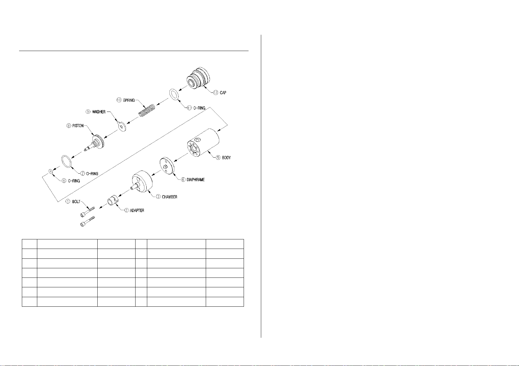
In case of disassembly for washing or replacing part, refer to①
"7.Exploded View & Parts List".
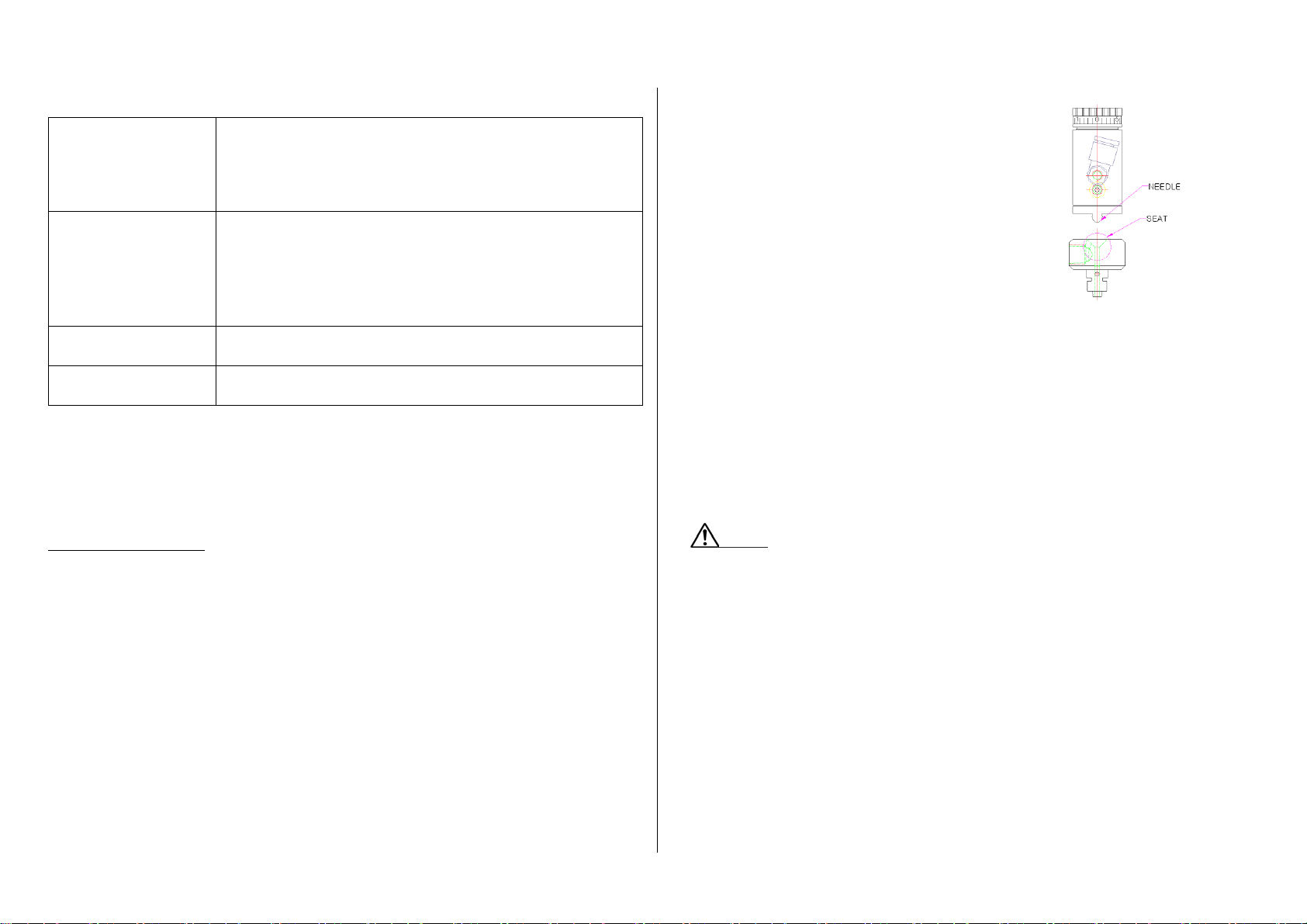
In case of washing valve head with②
sharp pin or others, try not to scratch
needle or seat part. If damaged you
need to replace parts because of
leakage.
5-2-3) Assembly
Diaphragm Assembly①
Loosen stroke control knob by turning twice counterclockwise.ⓐ
Separate valve head.ⓑ
Remove diaphragm by turning counterclockwise.ⓒ
Screw new diaphragm carefully to become horizontal toⓓpiston road
screw-thread.
Notice
If it isn't fit thread properly leakage may occur.
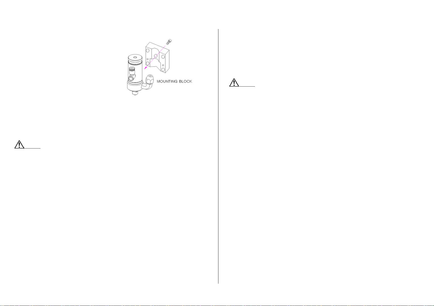
After fixing diaphragm at regular intervals(0.4mm) like the picture, forⓔ
matching cylinder body and mount screw, please turn to the
location that you want using a screwdriver like next picture.

To reinstall valve head fasten L-wrench bolt firmly.ⓕ
Fasten stroke control knob until it is closed. Then open it again untilⓖ
stroke is appropriate.
Notice
Scale may not indicate to ‘0’ of reference mark. In this case refer to
relative scale.(There is no problem to use.)
6. SECTIONAL DRAWING & DIMENSION
Cross-sectional View▶
Dimension▶

7. EXPLODED VIEW & PARTS LIST
No Part Name Spec No Part Name Spec
1BOLT M3*18 7O-RING AS016
2ADAPTER ∙8PISTON ∙
3CHAMBER ∙9WASHER ∙
4DIAPHRAGM ∙10 SPRING ∙
5BODY ∙11 O-RING P15
6O-RING P4 12 CAP ∙
Table of contents
Other Ban Seok Control Unit manuals
Popular Control Unit manuals by other brands

Cepex
Cepex EXTREME Series Installation and maintenance manual

AccuStream
AccuStream AccuValve On/Off Valve manual

Telit Wireless Solutions
Telit Wireless Solutions WE310F5-I Hardware user's guide

Spirax Sarco
Spirax Sarco BSK1 Installation and maintenance instructions

Mircom
Mircom RAX-332 quick start guide

Bosch
Bosch Rexroth ctrlX I/O XI322204 manual