TheJagWrangler RealGauge User manual
Rev 1.1
For more info or to purchase go to www.thejagwrangler.com
1
TheJagWrangler LLC
Jaguar XK8 / XKR 'RealGauge' Oil Pressure Option Installation &
Operation Manual
'96-'99
Left-Hand Drive
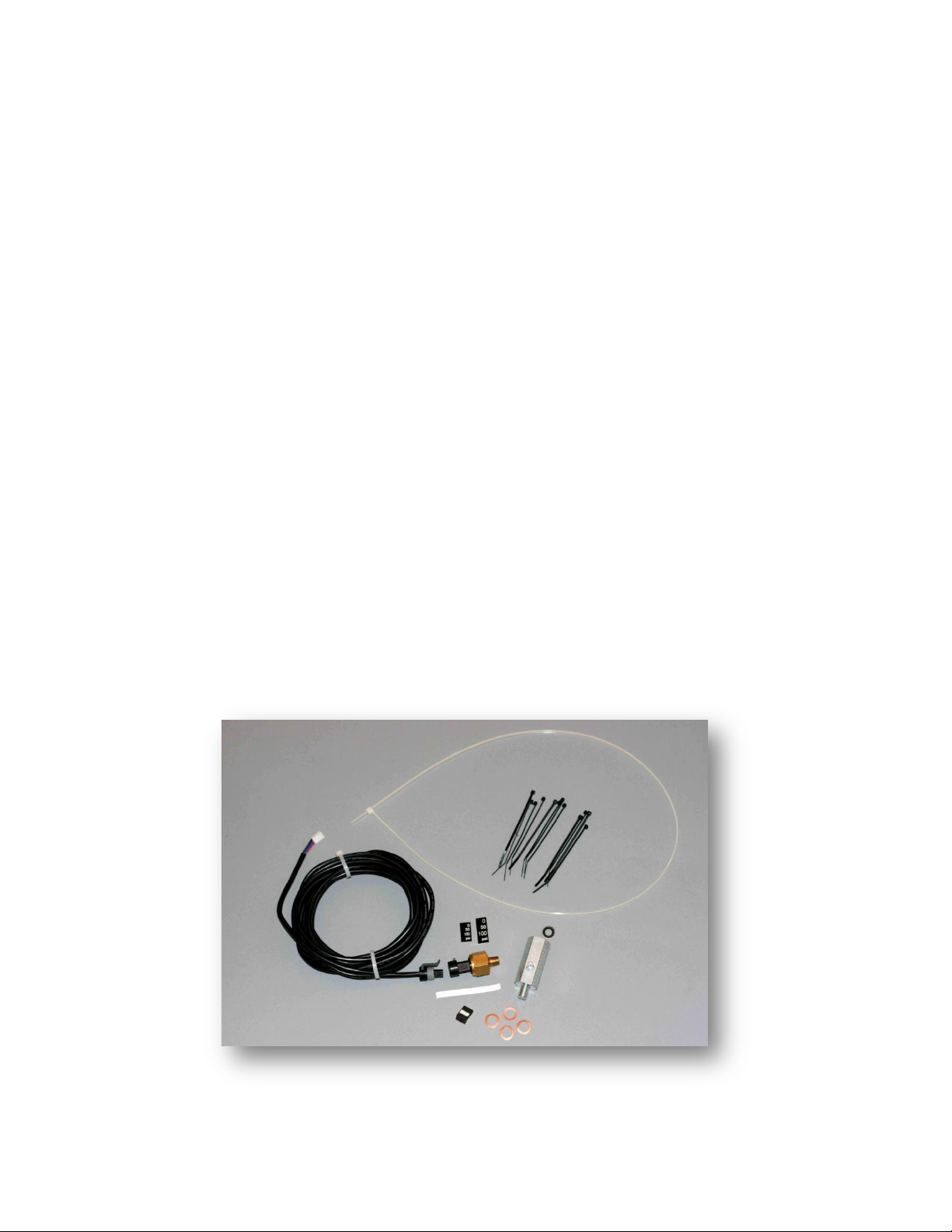
Kit Contents supplied:
Quantity 1 - 100 PSI automotive oil pressure sensor
Quantity 1- Oil pressure sensor cable
Quantity 1 - 4 pin connector body
Quantity 1- Tee adapter for oil pressure sensor and original factory pressure switch
Quantity 12- 4" Tie-Wraps
Quantity 1- 2.5" x 1/4" PTFE thread seal tape for new oil pressure sensor
Quantity 4- 10 mm inside diameter, 16 mm outside diameter, 1 mm thick copper seal ring and
spacer for tee adapter to engine block
Quantity 1- Replacement steel/rubber sealing ring for original factory pressure switch
Quantity 1- 36" long tie-wrap wire pulling tool (pre-attached to sensor cable)
Quantity 1- set of 12-point font numerical self-adhesive labels (usage optional).
Quantity 1- set of 16-point font numerical self-adhesive labels (usage optional).

Rev 1.1
For more info or to purchase go to www.thejagwrangler.com
2
Tools List (must be provided):
#2 Philips screwdriver
Ratchet or nutdriver set with 7mm and 8mm sockets.
Ratcheting torque wrench (recommended)
15/16" or 24mm wrench or deep socket
7/8" open end wrench
7/8" socket
13/16" or 21 mm wrench or deep socket
Slip joint pliers
Jack safety stands
Jack (you can use the emergency jack that comes with the car)
Sharp nail or awl
Vaseline or KY Jelly or silicone spray lube
T-20 internal torx driver
Scissors
Paper towels or old rags
Latex or nitrile rubber gloves (recommended)
Clean soft towel
Electrical tape
Engine oil
Pocket knife or exacto knife
Small wire cutters
Small basin or jar
Tube of RTV sealing compound
Small size metal paper clip
Handy items (may be helpful to have on hand if needed):
Toothpick
Superglue or Epoxy
Rev 1.1
For more info or to purchase go to www.thejagwrangler.com
3
Installation Procedure:
1. In order to proceed with the Oil Pressure Option, the installation of the RealGauge Module must be
completed through initial testing. Install the Oil Pressure Option prior to reinstalling the wood dash and
the kick panel.
2. Disconnect the battery again.
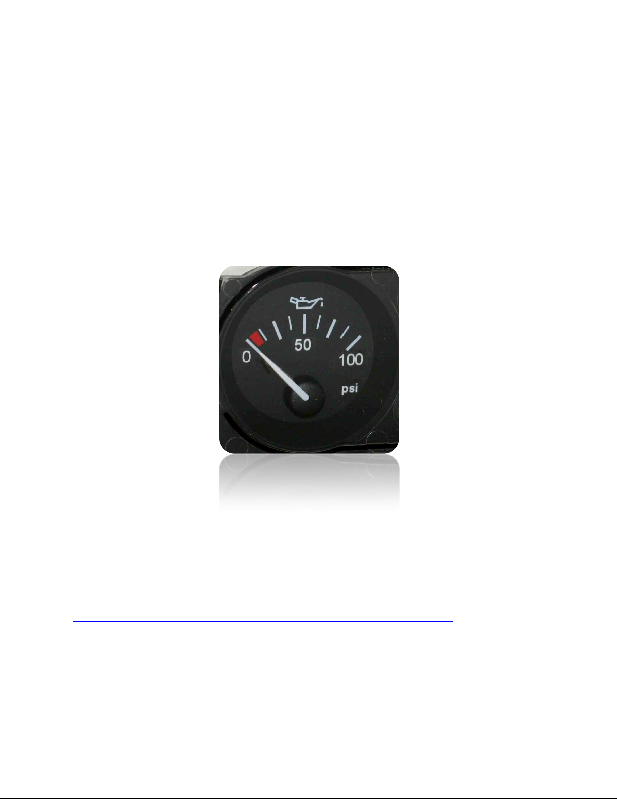
3. Decide if you want to add numerical scale label stickers to appear on the oil pressure gauge. It is
optional. If you choose not to add the numerical scale, skip directly to Step 10.
Please be aware that the scale numbers will not be backlit. This photo illustrates the scale number
labels applied:
Note that this example is shown in 16-point Helvetica font, which is the same as the numbers on the
voltage gauge. Twelve-point Helvetica font numerical stickers are also provided in the kit if you prefer
smaller numbers.
4. Remove the center 3-gauge instrument cluster wood paneling and remove it from the vehicle. See
this demonstrated in a video on YouTube at:
http://www.youtube.com/watch?v=H8AdOTMYfmY&feature=mfu_in_order&list=UL
5. Remove the four Philips screws from the 3-gauge cluster, unplug the cluster and remove it from the
vehicle.
Rev 1.1
For more info or to purchase go to www.thejagwrangler.com
4
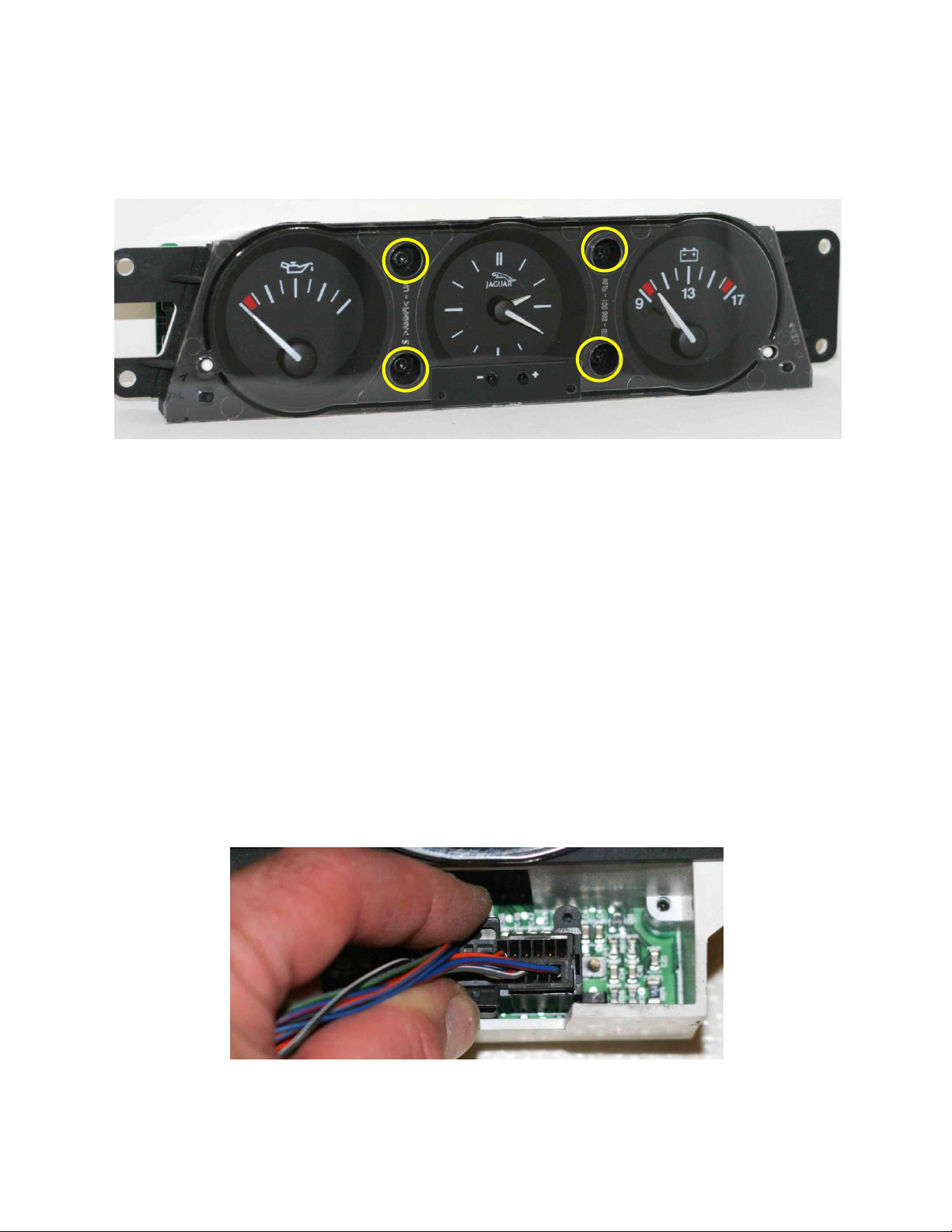
6. Remove the four T-20 torx screws from the front of the gauge cluster (circled in yellow below) and lift
off the clear front cover and set it aside. Remove the twin pushbutton actuator for clock setting and
put aside.
7. Carefully cut out the self-adhesive numbers with sharp scissors. Peel off the backing and apply the
ones you select as per the gauge face examples above. Note that the backing is slit in the center of the
label to ease removal. Use a toothpick to carefully align and position the adhesive labels before firmly
pressing them down. The gauge needle can be rotated gently as necessary without harm. (Be very
careful not to break off the black plastic needle stops...they are quite fragile and are necessary for
proper operation of the gauges. If you break a needle stop you will need to repair it with a tiny drop of
Superglue or Epoxy.)
8. Replace the twin pushbutton lock setting actuator and replace the clear front cover of the 3-gauge
cluster and the four T-20 torx screws.
9. Plug the 3-gauge cluster harness back in, put it in place and replace the four Philips screws.
10. Unplug the right side (smaller) main instrument cluster connector by depressing the opposing tabs
and pulling.
Rev 1.1
For more info or to purchase go to www.thejagwrangler.com
5
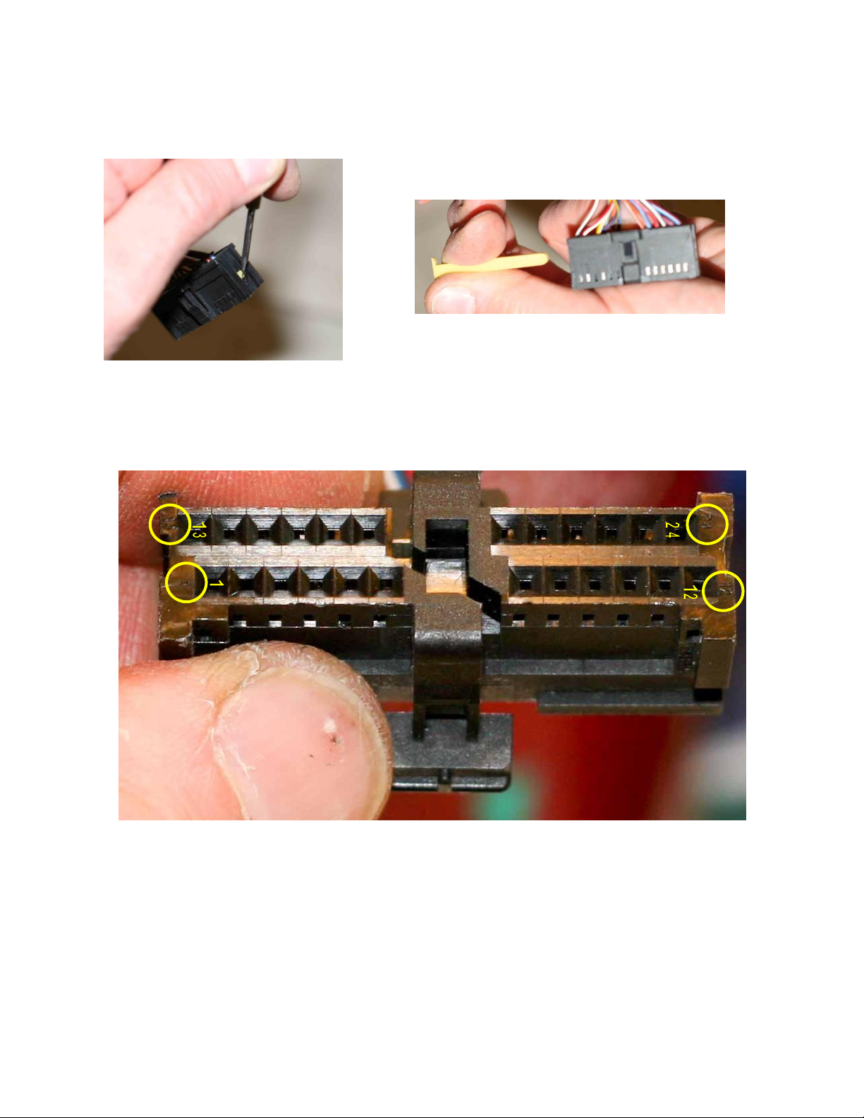
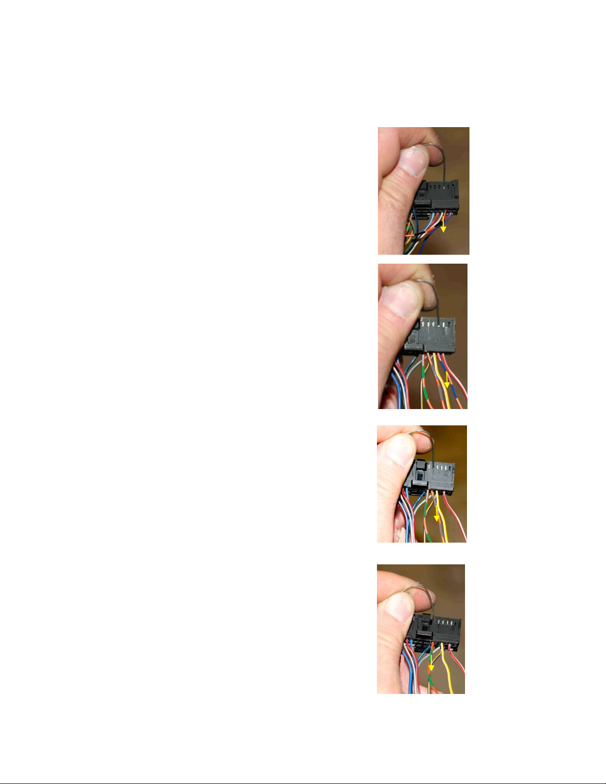
11. Depress the off-white nylon terminal retainer with a small screwdriver or awl and extract it out the
other side. Do not put excessive force on the wires with the retainer now removed.
12. Note the tiny pin number references embossed in the corners of the connector face (you may need a
bright light and a magnifier). They can be used to reference the other pin positions by counting.
Rev 1.1
For more info or to purchase go to www.thejagwrangler.com
6
13. Unfold the small paper clip. Using the point of the clip to gently depress the terminal locking tab in
the connector body window, gently pull the following wires out, one at a time from the black connector
body:
Orange-Black, position 10
Orange-Blue, position 15
Orange-Slate, position 17
Orange-Green, position 18

Rev 1.1
For more info or to purchase go to www.thejagwrangler.com
7
14. Check that all of the remaining pins are fully seated, and plug the off-white nylon retainer back fully
into the instrument cluster connector.
15. Check that the locking tab on each terminal stands out about 10 degrees, and gently bend it back
into position if necessary.

Rev 1.1
For more info or to purchase go to www.thejagwrangler.com
8
16. Insert the terminals into the four position connector body supplied in the kit. Hold the four pin
connector with the large openings facing you, and the white plastic insert facing down as shown below.
Position 1 is on the right, and position 4 is on the left. Terminals are inserted with the locking tab facing
down with the connector body held as shown.
Orange-Slate, position 1
Orange-Green, position 2
Orange-Blue, position 3
Orange-Black, position 4
Take care to get this correct the first time. These pins are difficult to extract from the 4-position
connector body. If an error is made here, please contact whitexkr@comcast.net for further directions.
17. Firmly depress the white insert in the connector body to lock the pins in place. The white insert may
not move very much.
18. Plug this four conductor connector into the mating RealGauge harness connector attached to the
gray four conductor cable (wire colors on the right may vary from photo below).
1
4
1
4
Rev 1.1
For more info or to purchase go to www.thejagwrangler.com
9
19. Plug the black right-hand instrument connector back into the instrument cluster.
21. Jack up the front end or the right-hand front corner of the car, as if you were going to access the oil
filter for an oil change. Support the car on jack stands for safety.
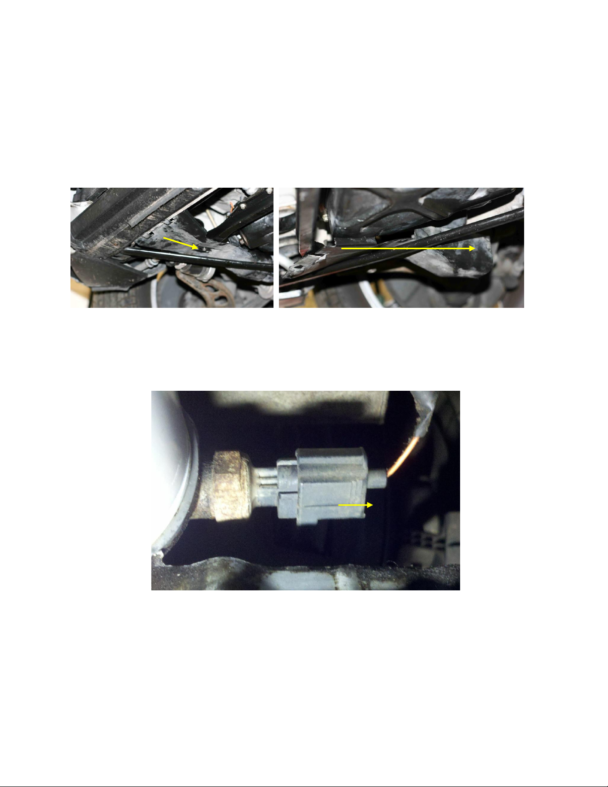
22. Locate the plastic cover (air duct) over the oil filter on the front right side under the engine. Using a
7mm socket remove the single screw and slide the plastic cover off toward the rear of the car. Note
that on some cars this plastic cover might be missing.
23. Squeeze the connector tab and unplug the connector from the oil pressure switch (the one with the
orange wire) adjacent to the oil filter. If your car has another sensor with two wires (not all do), leave
the other sensor alone.
Rev 1.1
For more info or to purchase go to www.thejagwrangler.com
10
24. Remove the oil pressure switch using a 13/16" or 21mm deep socket. Have a basin or jar ready to
catch the drips. Expect about 2 to 4 oz. of engine oil to drip out. Clean the mating surface on the engine
block. Protective rubber gloves are recommended for this step.
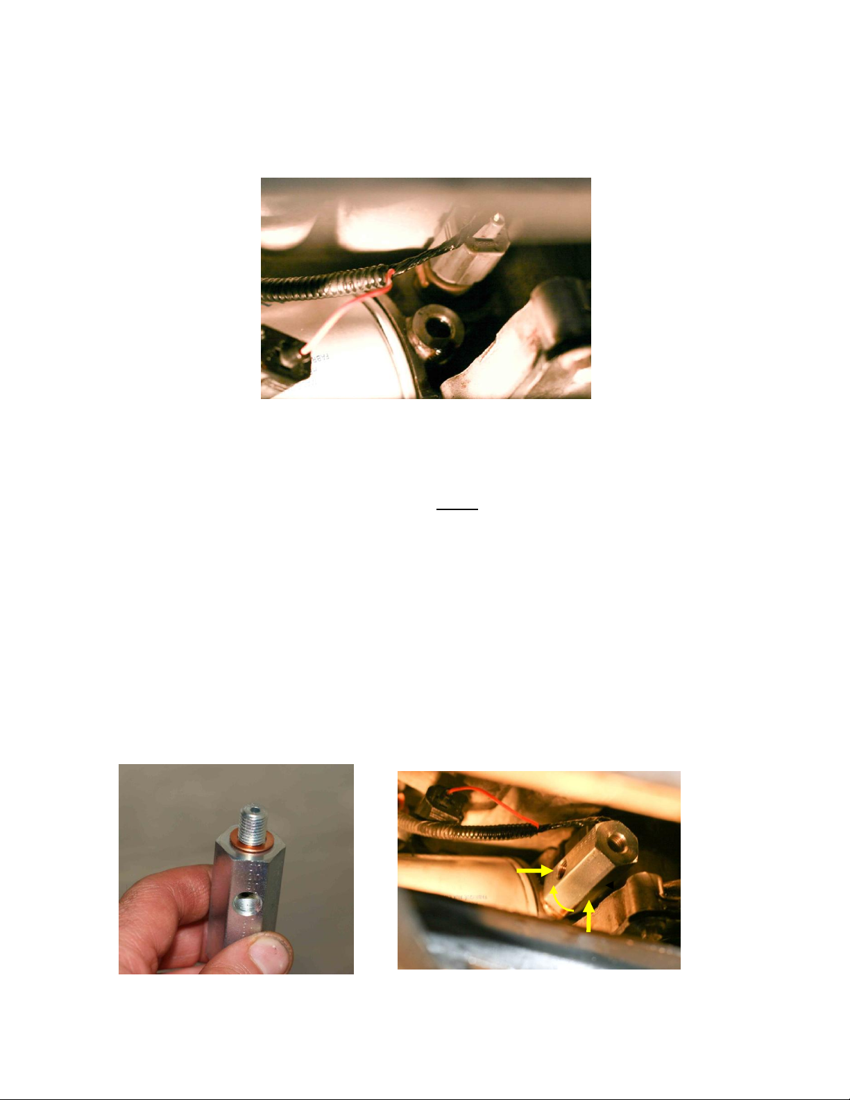
25. Read this and understand this entire step before proceeding. Place one copper seal washer from the
kit on the tee adapter and screw it into the engine block. IMPORTANT: DO NOT use thread sealing
tape on these threads. Finger tighten until it is snug. Only if the side port on the adapter now
approximately faces down when finger tight, tighten about an additional 90 degrees (to about 13 Nm)
with a 7/8" socket so the port faces the righthand side of the car (your left). Do not overtighten!
If the side port on the bottom of the adapter does not face down, remove the adapter and add additional
copper washers so the it will roughly face down once finger tight (Four washers are supplied in the kit,
use only as many that are needed). Each washer will add about 70 degrees of rotation. Note the side
port of the tee adapter must face the right-hand side of the car (your left looking at the oil filter from the
front of the car) once it is torqued to 13 Nm to provide proper clearance for the pressure sensor.
Tightening the tee adapter from finger tight when the port is facing down to 13 Nm will take up the final
90 degrees so the port faces the right-hand side of the car.
The final position after proper tightening to 13 Nm is shown below in the photo on the right.
Start with one
copper washer,
add additional as
needed.
Port position when
finger tight.
Final port
position at 13 Nm
Rev 1.1
For more info or to purchase go to www.thejagwrangler.com
11
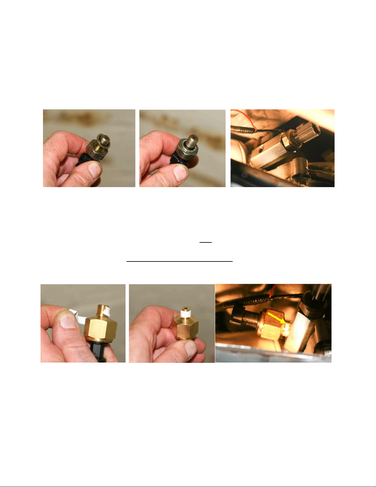
26. Remove and discard the old rubber and metal sealing ring from the oil pressure switch that was
removed from the vehicle. Apply a drop of clean engine oil to the new rubber and metal sealing ring
supplied in the kit and push it over the threads until it bottoms at the base of the oil pressure switch.
Screw the oil pressure switch into the END port of the tee adapter. IMPORTANT: DO NOT use thread
sealing tape on these oil pressure switch threads. Tighten to temporarily to about 9 Nm with a 13/16"
or 21mm deep socket (it will be removed again in a later step for bleeding and tightened to its final
torque). Do not overtighten!
27. Wrap the supplied white 1/4" x 2.5" PFTE thread sealing tape clockwise (with port facing away from
you) around the brass threads of the new oil pressure sensor. Make sure not to cover the sensor port
hole with tape. Screw the oil pressure sensor into the SIDE port of the tee adapter. Tighten to 6-8 Nm
with a 15/16" or 24 mm deep socket. IMPORTANT: DO NOT SCREW THIS SENSOR ALL THE WAY IN THE
THREADED OPENING LIKE YOU DID FOR STEPS 25 and 26. THIS SENSOR IS DESIGNED TO BE
TIGHTENED TO 6-8 Nm only. SOME THREADS MAY STILL BE VISIBLE. THIS IS CORRECT. Do not
overtighten!
28. Using an old rag or paper towels, clean off any oil drips thoroughly from the engine and chassis.
29. Plug in the oil pressure switch connector with the orange wire at the oil pressure switch. If the wire
now seems too short to reach, feed some additional slack by pulling the black corrugated plastic harness
from which the orange wire is fed. Do not pull the orange wire itself. Do not install the connector so
the orange wire is under constant tension.
Some threads may still be visible
after tightening
Rev 1.1
For more info or to purchase go to www.thejagwrangler.com
12
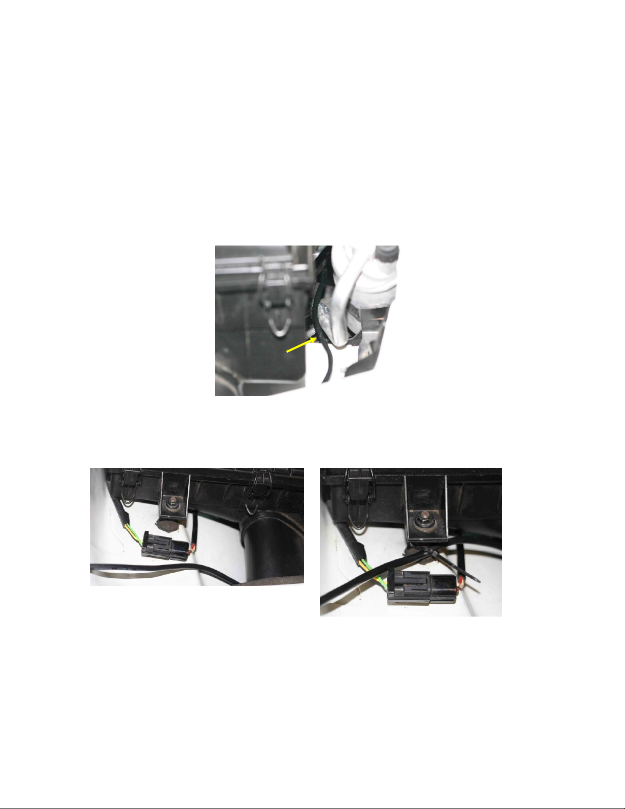
30. Plug in the supplied oil pressure sensor 3-wire cable into the oil pressure sensor and add a tie wrap
to tie the two harnesses together.
31. Thread the oil pressure sensor cable from below to the top of the engine compartment up near the
radiator on the right side of the car so it emerges at the top between the airbox and the air conditioning
receiver/dryer near the right front fender as shown below. Pull the full length of the cable through. Tie
wrap the cable to nearby hoses or harnesses so that it is well clear of the fan and the serpentine belt
and pulleys underneath the car. Be especially careful to keep it clear of the nearby alternator pulley.
This route was chosen because it is important the cable is routed clear of the exhaust manifold or it will
be damaged from the exhaust heat. It is also easy to route without lots of disassembly.
32. Route the sensor cable under the airbox snorkel and tie wrap it to the airbox bolt.
Airbox
Receiver/
dryer
Rev 1.1
For more info or to purchase go to www.thejagwrangler.com
13
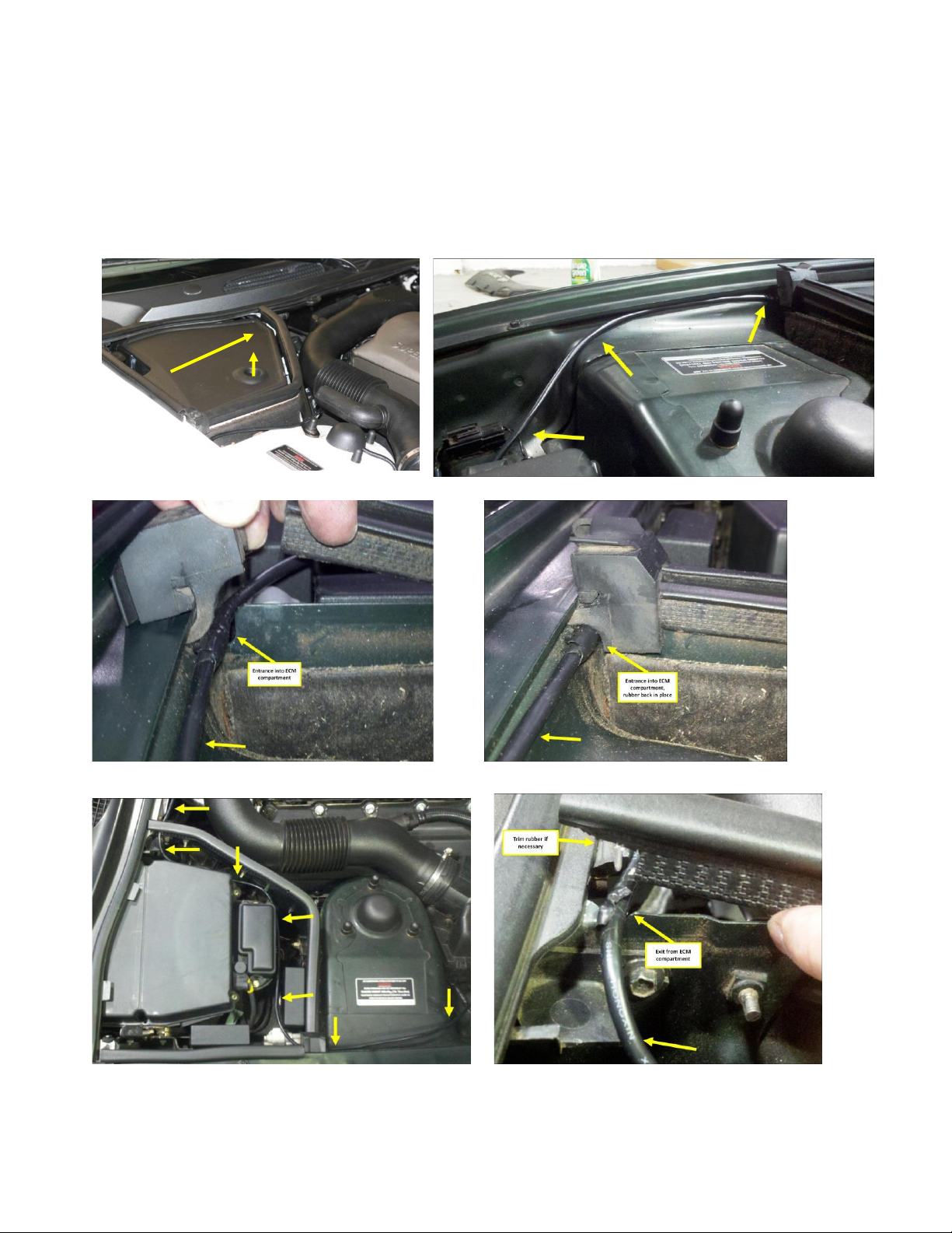
33. Remove the cover of the ECM compartment by lifting from the hole on top and pulling it away from
the fender. Continue routing the sensor cable under the fender lip and into the ECM compartment.
lifting the rubber block to gain access to the ECM compartment. Wrap three turns of electrical tape
around the cable before inserting it in the grooves at the entrance and exit of the ECM compartment.
Replace the ECM compartment cover.

Rev 1.1
For more info or to purchase go to www.thejagwrangler.com
14
34. Route across the firewall, adding zip ties as shown.
Rev 1.1
For more info or to purchase go to www.thejagwrangler.com
15
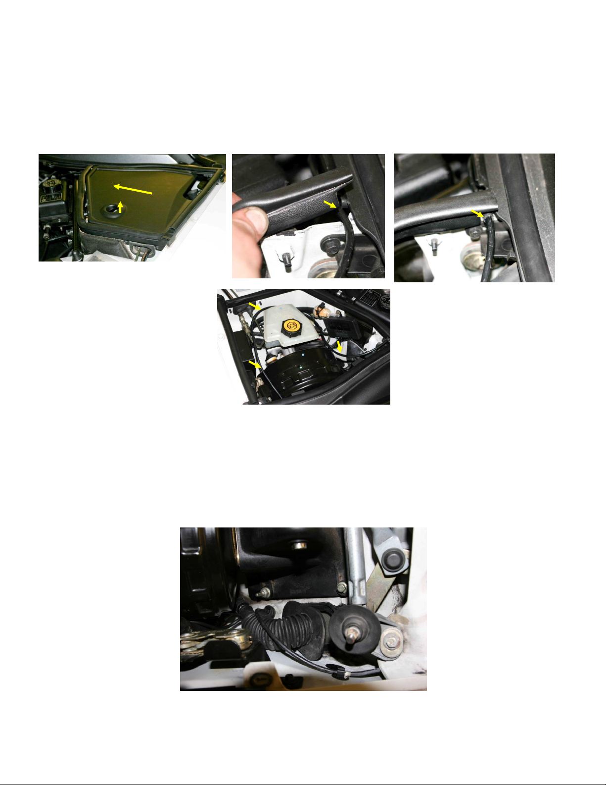
35. Remove the brake booster compartment cover by lifting from the hole on top and pulling it away
from the fender. Lift the weatherstrip of the brake booster compartment nearest the windshield and
insert the sensor cable in the groove under the weather strip at the back of the brake booster
compartment. Wrap three turns of electrical tape around the cable before inserting it in the groove;
then replace the weatherstrip. Route the cable around the master cylinder as shown.
36. Pry loose the accordion rubber boot near the fender on the bottom of the brake booster
compartment (see photo below). Use a flat blade screwdriver if necessary to assist. There may be a
rubbery adhesive bond between the rubber and metal that you need to break. (It is not absolutely
necessary, but if you have difficulty with this step remove the wipers and the plastic grille under the
wipers and to gain easier access.)
Rev 1.1
For more info or to purchase go to www.thejagwrangler.com
16
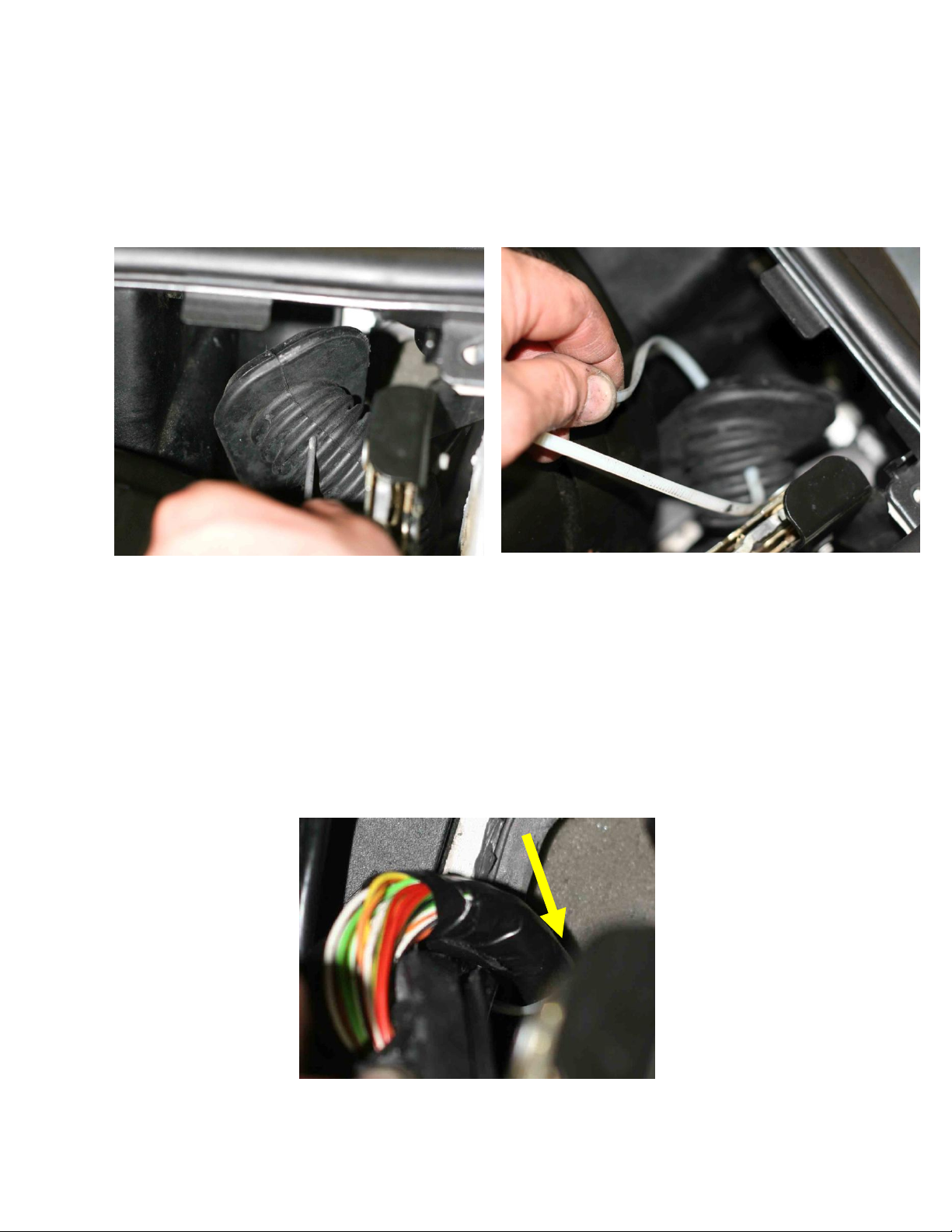
37. Poke a hole in the top of the accordion boot with a nail or awl about three ridges up from the base.
Use a pocket knife or Exacto knife to expand the hole slightly with two crossing 1/8" to 1/4" slots.
Thread the sensor cable zip tie through from the outside to the inside of the boot. Use some Vaseline,
KY Jelly or silicone lubricant where the cable is looped over to ease pulling the entire cable length
through the hole in the rubber boot.
38. Now poke the nylon fish line at the end of the sensor harness through the gap in the foam insulation
below the brake booster compartment, exactly where the multicolored cable is routed into the
passenger compartment. Push through at least 18 inches or so. Open the driver door and locate where
the fish line has emerged under the dashboard. Be patient, this may take several tries. Pull it all the
way through, into the passenger compartment, along with the cable. (It is not absolutely necessary, but
again, if you have difficulty with this step remove the wipers and the plastic grille under the wipers and
to gain easier access. It may also help to place a light in the footwell and to guide the nylon fish line
toward the light.)
Rev 1.1
For more info or to purchase go to www.thejagwrangler.com
17
39. Press the rubber flange of the accordion boot securely back into the bottom of the brake booster
compartment. It is recommended to use some RTV sealing compound on the lip where the base of the
rubber flange meets the metal opening. Replace the plastic grill and wipers if they were removed
earlier. Replace the brake booster compartment cover.
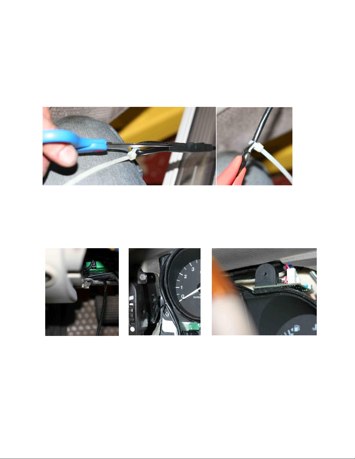
40. Using scissors, carefully cut and remove the heatshrink tubing that was used to create a pulling loop
in the sensor cable. Also use wire cutters to remove the long zip tie that was used for pulling.
41. Route the sensor cable over kick panel mounting rail below the dashboard. Then route sensor cable
up and alongside the left of the main instrument cluster and over the top of the cluster. Plug the sensor
cable into the 3-pin connector on the front edge of the RealGauge module with the red wire on the left
and the black wire on the right.
42. Reconnect the battery negative cable with the key removed from the car. If possible, have an
observer in the car watching the coolant gauge AND the oil pressure gauge as you reconnect the
battery. BOTH gauges will now undergo an initialization and test sequence automatically when the
battery is connected, first the coolant gauge, followed by the oil pressure gauge. First the needle will
vibrate at the low end of the scale for a second or two. This is the calibration process. Then, for the test
Rev 1.1
For more info or to purchase go to www.thejagwrangler.com
18
sequence, the needle will swing to the top of the scale, the alarm will go off briefly while it hits the red
area, after which the needle will return to the low end of the scale.
43. Reset your windows after reconnecting the battery as follows: Get in the vehicle and shut the doors.
Turn on the ignition fully, but do not start the car. Roll the windows all the way down, holding the
window down button until you hear a click. Now roll the windows up, holding the up button until you
hear a click. (On non-North American cars you may also need to reset the radio code. The code can be
obtained from your dealer with proof of ownership if you do not have it.)
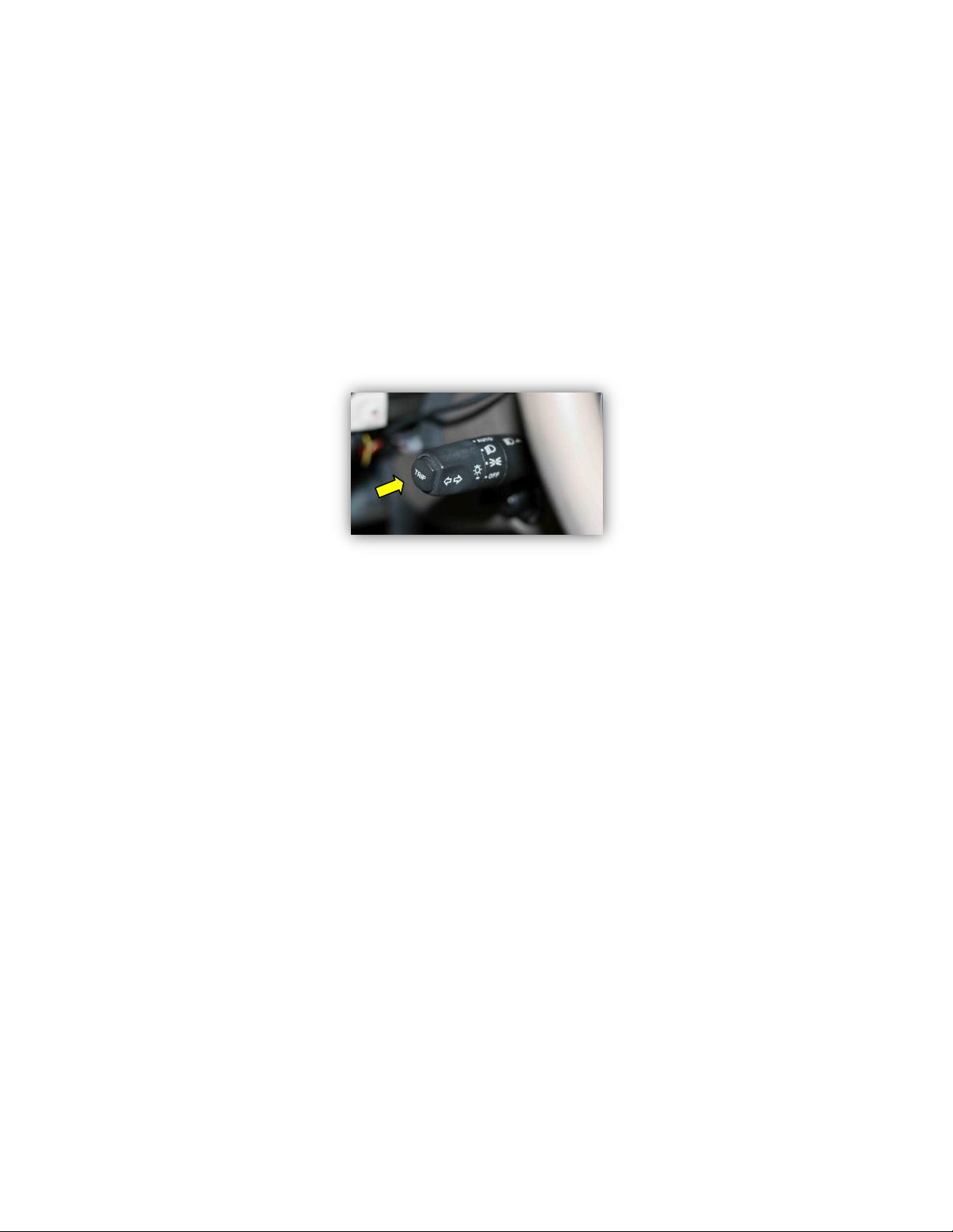
44. Now turn on the ignition fully, but do not start the car. Press and hold in the trip cycle button (at the
end of the left/right turn blinker stalk) for at least four seconds.
After about four seconds another test sequence should initiate. The coolant gauge needle should swing
to the top of the scale, the alarm will go off briefly while it hits the red area, and then the needle will
return to the low end of the scale. This will then repeat for the oil pressure gauge. History of peak
temperature and minimum oil pressure from any previous engine starts in memory will then play back
from memory, and then you should then hear four quick beeps in a sequence. (Note that the memory
will register zero oil pressure for any engine starts performed prior to the oil pressure sensor
installation. This is normal).
45. Now start the engine. Note a reading on the oil pressure gauge. If there are any alarms or warnings
immediately shut off the engine and recheck your sensor connections.
46. Allow the engine to run for at least 3 minutes and make sure no oil is leaking out at the sensor
connections. Shut off the engine.
47. Now bleed the air out of the tee adapter. Do not skip this step, it is necessary to prevent false low
oil pressure readings or alarms at idle. To perform the air bleeding, unplug the oil pressure switch
connector (orange wire) and remove ONLY the oil pressure switch (at the END of the tee) again using a
13/16" or 21mm deep socket. Have a basin or jar ready to catch the drips from the end of the tee.
Once the oil stream starts flowing out, after 3 to 4 seconds replace the oil pressure switch again and
tighten the oil pressure switch, this time to 13 Nm. Then plug in the connector again. Again clean up
any oil drips with a rag or paper towels. Protective rubber gloves are recommended for this step.
48. Allow the engine to fully warm up and check for oil leaks by the sensors that were just installed.

Rev 1.1
For more info or to purchase go to www.thejagwrangler.com
19
49. If there are no leaks, shut off the engine and replace the plastic cover over the oil filter and 7mm cap
screw.
50. Lower the vehicle to the ground.
51.Check your engine oil level and top it off if necessary.
52. If everything is operating normally, add a few tie-wraps to neaten the harness installation beside
and below the instrument cluster to minimize wire movement. Clip the tie wrap tails.
Next replace the screws for the instrument cluster and the wood bezels, and reinstall the lower kick
panel.
Remember to reinstall the connectors for the trip button on the instrument cluster wood bezel, and the
valet switch and aspirator fan on the kick panel.
Congratulations on a successful installation!
Having Difficulty?

Rev 1.1
For more info or to purchase go to www.thejagwrangler.com
20
Operation:
The RealGauge Module oil pressure option does not need any special attention on a normal day-to-day
basis. You will now see normal fluctuations in oil pressure as you drive, depending on the engine
temperature, the engine speed, and oil viscosity. Normal fluctuations can be quite large, typically from
about 10 psi to 75 psi. By noticing changes to normal oil pressure patterns, you increase the likelihood
that you can have oil pressure problems evaluated and repaired before they become serious, expensive
and potentially leave you stranded.
There are some special features which are available to test the unit, provide alarm, suppress the alarm,
and provide a historical account of oil pressure:
Audible Alarm (High temperature or Low Oil Pressure)-
An over-temperature condition (over 230 degrees F) or a low oil pressure condition, as detected by the
Jaguar OEM oil pressure switch (set at 6 psi) or the optional Realgauge oil pressure sensor (set at 8 psi)
will cause an audible alarm, which is a high pitched continuous tone. In either case, the car should be
pulled off the road as soon as it is safe to do so and the engine shut off to prevent engine damage.
Temporary Audio Alarm Suppression-
If the audio alarm goes off indicating an over-temperature condition or low oil pressure condition, the
alarm can be suppressed by pressing and holding in the trip cycle button (at the end of the left/right
turn blinker stalk) for 1.5 seconds. (Afterwards, you can manually cycle the trip cycle button back to
your desired display). The alarm will then remain suppressed until the ignition is turned off no matter
what the temperature or oil pressure reading is, and then re-enabled the next time the ignition is turned
on again.
Test Mode / History Replay-
With the ignition fully on, but the engine off, press and hold in the trip cycle button (at the end of the
left/right turn blinker stalk) for four seconds. (Afterwards, you can manually cycle the trip cycle button
back to your desired display). This invokes test mode where the needle will swing to the top of the scale,
and the alarm will trigger briefly, as a test, when it hits the red area of the scale. Then it will return to
the low end of the scale.
At the end of the test mode the History Replay will automatically begin. The peak temperature and
minimum oil pressure recorded during each engine run (oldest first) since installation will replay
Table of contents
Other TheJagWrangler Automobile Accessories manuals

Popular Automobile Accessories manuals by other brands

Kuda-Phonebase
Kuda-Phonebase 083850 Installation instruction

Hollywood
Hollywood SR1 installation instructions

BPW
BPW ECO Tronic EBS Operating and installation instructions

Whispbar
Whispbar K719 installation instructions

travall
travall TDG 1588 FITTING INSTRUCTION

OTC Tools
OTC Tools OTC 3209 quick start guide


HEIDELBERG
HEIDELBERG Wallbox Home Eco installation instructions

Prorack
Prorack K1003 manual

Intellitronix
Intellitronix AP5001 installation guide

METROVAC
METROVAC AIRFORCE BLASTER B3-CD instruction manual

Allen Sports
Allen Sports ZN540 instructions

Modula
Modula RE-CARGO KIT 2 PORTABICI Assembly instructions