PFX ProFormX A-ARM LIFT KIT User manual

• Front Suspension
• Front Spindles
• Upper A-Arms
• Rear Goalpost
• Front Shocks
• Front U-Bolts
• Sway Bar Bracket
• Hardware Pack
TOOLS NEEDED PARTS LIST
Fits Yamaha® Drive®
A-ARM LIFT KIT
BY
Bolt Length Gauge
Front Suspension
Upper A-Arms
Front Spindles
Front U-Bolts
Front Shocks
Rear Goalpost Sway Bar Bracket
• 21mm socket
• 19mm socket
• 18mm socket
• 17mm socket
• 14mm socket
• 13mm socket
• 10mm socket
• 3/8 Allen Head
Socket
• Rotary Cutting Tool
• 18mm wrench
• 17mm wrench
• 14mm wrench
• 13mm wrench
• 12mm wrench
• 10mm wrench
• 3mm Allen Wrench
• Adjustable Wrench
• 7/16” Drill Bit
• Cordless Drill (optional)
Warning
Label

STEP 2
STEP 3
Switch key to the OFF position and
engage the Parking brake. Chock rear
wheels.
Place TOW/RUN switch to TOW.
Before lifting cart, remove factory wheel
covers and break loose lug nuts with a
19mm socket.
Lift front of cart and place jack stands
under frame as shown.
Remove front bumper by taking out the
four bolts marked with a 10mm socket.
Retain bumper and hardware.
Remove front wheels.
1) Remove dust cap and cotter pin from
hub. Then remove wheel hub using a
19mm socket
.
2) Remove cotter pin from tie rod and
use a 17mm wrench and socket to
remove steering rack from spindle
.
Retain all parts and repeat on driver’s
side.
STEP 1
1
2

STEP 5
STEP 6
STEP 4
STEP 7
Using a 14mm wrench and socket,
remove and retain the factory A-arm
bolts shown.
Remove and retain the upper shock
bolts using a 14mm wrench and socket.
Caution: Once upper shock bolts
are removed, front suspension will
be loose and free to drop.
The only item remaining should be
the steering rack as shown.
Using the supplied U-bolts and hardware,
attach the Front Suspension to the frame
as shown.
Do NOT fully tighten bolts until after next
step.

STEP 8
STEP 9
STEP 10
Using the supplied 10mm x 25mm bolts
and washers, secure the front half of
the Suspension to the frame. Tighten
U-bolts and bolts using a 17mm wrench/
socket.
Note: The center mounting tabs of
Suspension should go behind the
crossframe as shown.
Using the retained bolts from STEP 4,
attach the new Upper A-Arms to the
factory a-arm mounting locations. Use
a rubber mallet if needed to guide the
A-Arm into place.
Note: The A-Arms should oset to
the rear of the cart as shown.
Important: Now is good time to grease
the A-Arm zerk ttings.
A) Attach Spindles to A-Arms using
the supplied Allen Head Bolts and a
3/8” Allen head socket.
B) Upper Heim Joint should be set out at
1/4” of thread as shown.
Note: Use a 3mm Allen head wrench to
back out set screw if needed for proper
spindle bolt penetration.
Do NOT re-tighten set screws or use
thread locking adhesive on Allen
head bolts until after alignment
STEP 25.
*Front of Suspension should
be even with cart frame*

STEP 11
STEP 12
STEP 13
Using the retained hardware from STEP
5, attach the new Shocks to the upper
shock mounts as shown.
Then attach lower shock mounts to the
Upper A-Arm mounts using the 10mm x
55mm bolts and hardware.
Attach the steering rack to Spindle
arms using the retained hardware
from STEP 3.
Install factory wheel hubs to Spindles
using retained nut from STEP 3. Tighten
all the way, then back nut o quarter to
half a turn so hub spins freely.
Then reattach cotter pin and dust caps
retained from STEP 3.
You can now install your new front tires/
wheels using 12mm Lug Nuts and
remove jack stands.
We recommend 22-23” tires and 12-
14” Wheels for proper clearance.

STEP 15
STEP 16
STEP 14
REAR LIFT INSTALL
Disengage parking brake and chock
front wheels. Use a oor jack under rear
end to lift rear of cart up and place jack
stands under frame.
Remove rear tires using a 19mm socket.
Note: Leave oor jack under rear end to
support weight during install.
Remove motor cover by taking out
the two plastic factory rivets at bottom
corners. Retain all.
Using a 14mm socket and wrench
remove upper bolts from shock mounts
as shown. Retain bolts. (Passenger side
shown in picture)
With shock bolts free, carefully lower
rear end to allow enough room for Rear
Goalpost to t between top of shocks
and shock mount from previous step.

STEP 17
STEP 18
Top
Bottom
STEP 19
Insert Rear Goalpost into upper shock
mounts with the angled end pointing
towards the front of cart as shown.
A rubber mallet may be needed to guide
Goalpost into factory mounts.
Using bolts from STEP 15, secure
Goalpost. Only hand tighten bolts until
after next step.
Using the oor jack, lift rear end up and
guide factory shocks into new Rear
Goalpost mounts.
Secure shocks using the supplied 10mm
x 55mm bolts as shown with a 17mm
wrench and socket.
Tighten bolts from step 17 using a 14mm
socket and wrench.
Remove factory bagwell bolt shown with
a 10mm socket, discard bolt.
With bolt removed, drill a hole through
the frame using a 7/16” drill bit.

STEP 21
STEP 22
STEP 23
STEP 20
Remove factory sway bar bolt from
frame mount using a 17mm wrench and
socket, keep bolt and nut for next STEP.
Attach top of Sway Bar Bracket to the
frame and bagwell using the supplied
10mm x 90mm Bolt and hardware as
shown. Tighten with a 17mm socket and
wrench.
Using the hardware from STEP 20,
attach sway bar to the bottom hole of the
Sway Bar Bracket.
Tighten with a 17mm wrench & socket.
Attach new Sway Bar Bracket to the
frame mount using the supplied 12mm x
35mm Bolt and hardware. Use a 18mm
wrench and 19mm socket to secure in
place.
Do NOT fully tighten until after STEP
24.

STEP 24
Due to clearance issues with larger
wheels/tires you will need to trim the
rear of each side skirt.
Follow the curvature of the fender well
and mark a cut line as shown.
Using a rotary cutting tool trim o the
pointed bottom corner and use sand
paper to clean the edges.
You can now install new rear tires/
wheels using 12mm lug nuts.

After installing this lift, the front wheels must be properly aligned. Failure to properly align the front
wheels may result in decreased ability to control the golf cart which may result in a rollover or crash.
IMPORTANT: Camber and toe must be adjusted for proper operation.
CAMBER ADJUSTMENT
TOE ADJUSTMENT
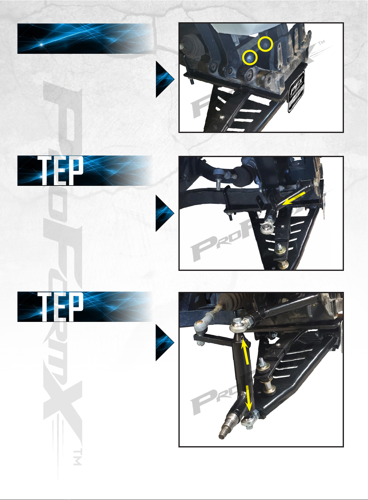
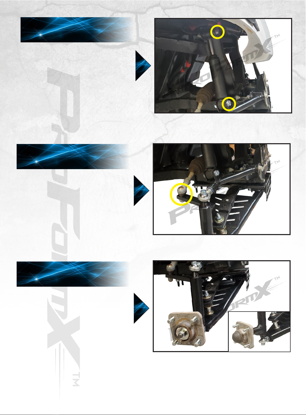
To adjust for proper camber, use a framing square
or level to verify the tire is resting at a 90° angle
to the ground. Lift front of cart with a oor jack.
First adjustment will be at the lower A-Arm (A).
Using a adjustable wrench, adjust the lower heim
joint in or out as needed to achieve proper 90°.
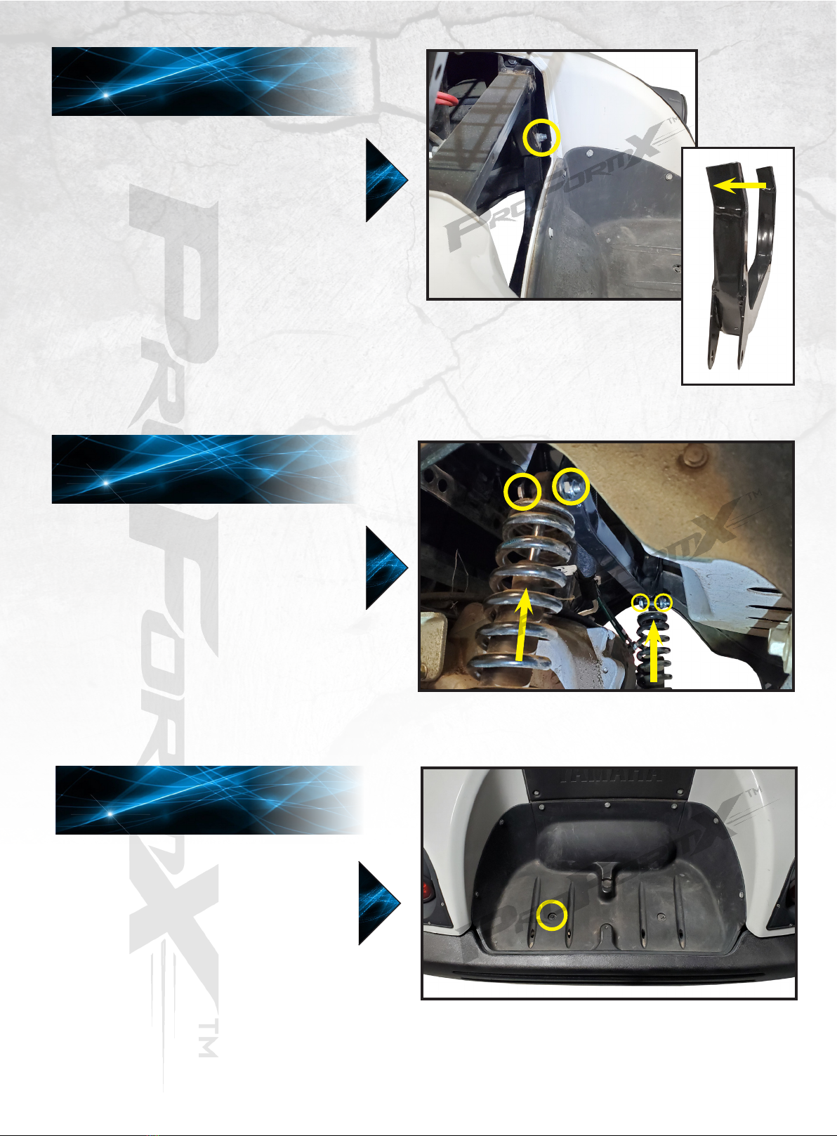
If further adjustment is still needed, remove the
front tire and temporarily remove the spindle bolt
(B) to free heim joint. Loosen heim joint nut with
a adjustable wrench and screw in/out heim joint
as needed.
Re-tighten nut, reattach spindle, and front tire.
Check camber again, if further adjustment is
needed, repeat process above.
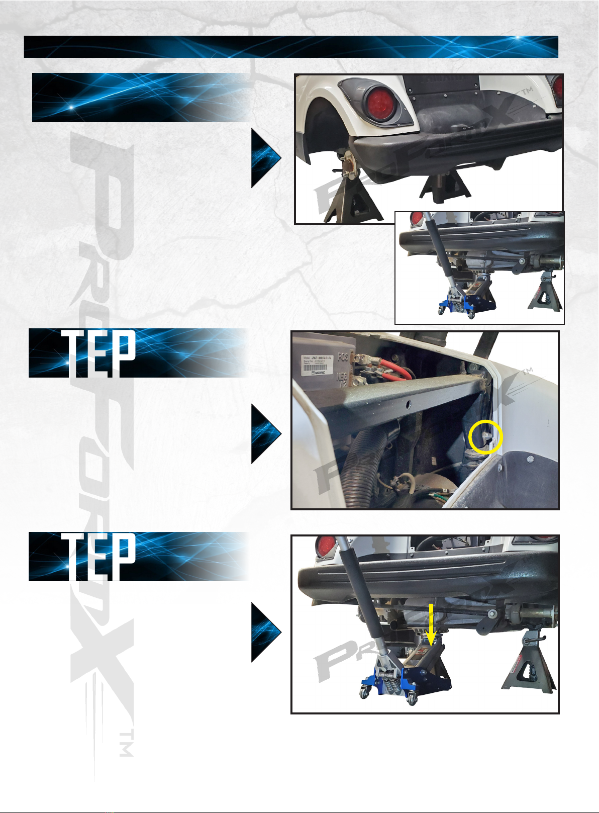
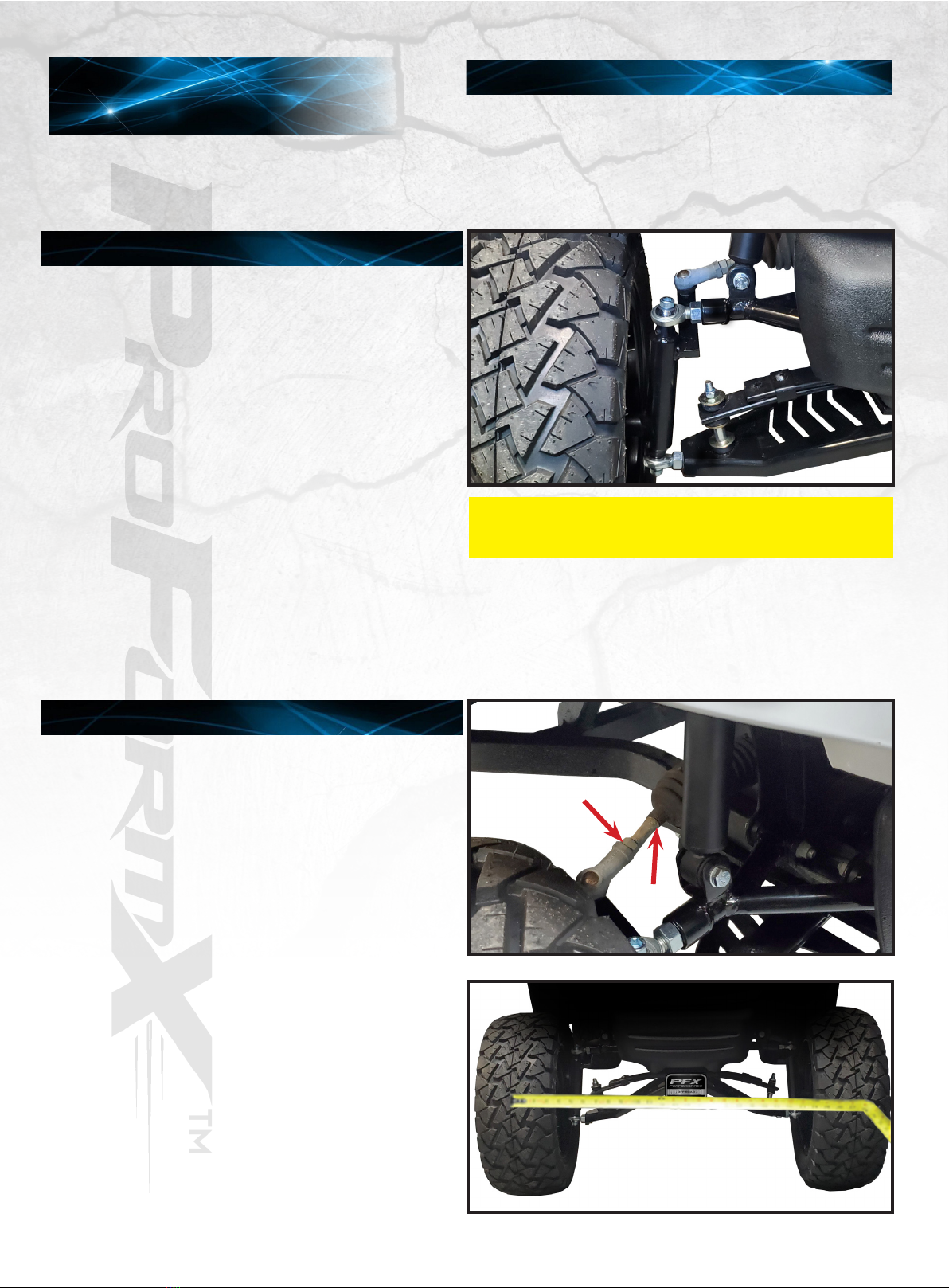
Ensure tires are pointing as straight as possible
and steering wheel is in the centered position.
First, nd a common point to measure from on
the inside front and inside rear of tires. You will
need to adjust the steering arms until the front
measurement is 1/4” greater than the rear
measurement. Tires should toe OUT in the front.
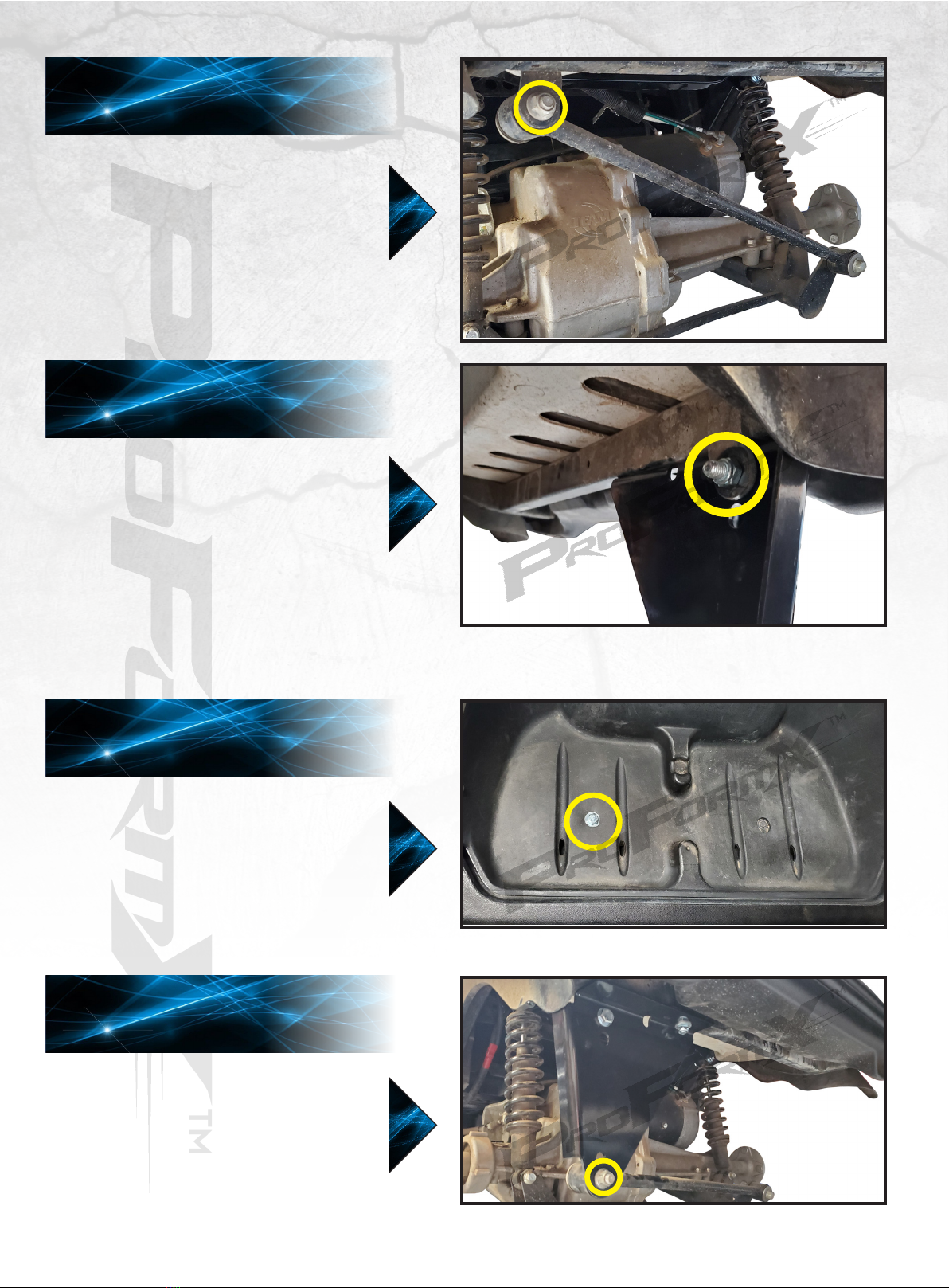
To adjust steering rack, loosen nut on tie rod end
(C) with a 17mm wrench and adjust tires in or out
using a 12mm wrench on the steering rack (D).
Tighten nut on tie rod end
when complete.
Drive the cart around and then recheck your
alignment. Readjust if necessary
A)
B)
C)
D)
Be sure to use threadlock adhesive on spindle
bolts and retighten set screws in spindles.
STEP 25 WARNING
ALIGNMENT INSTRUCTIONS

Bolt Length Gauge
HARDWARE LIST
MYPROFORMX.COM
Club Car®, Precedent®, and DS® are registered trademarks of Ingersoll Rand, Inc. E-Z-GO®, TXT®, and RXV® are registered
trademarks of Textron Innovations, Inc. (“Textron”). Yamaha®, G-14®, G-19®, G-22® G-29®, and Drive2® are registered trademarks
of Yamaha Golf-Car Company and Yamaha Motor Corporation (“Yamaha”). Reference to Club Car®, E-Z-GO®, or Yamaha® or
their associated trademarks and products is only for purposes of identifying golf carts with which this ProFormX™ product is
compatible. ProFormX™ products are aftermarket parts and are not original equipment parts. ProFormX™ is not connected or
affiliated with or sponsored by Club Car®, E-Z-GO®, or Yamaha® or endorsed by Ingersoll Rand Inc®, Textron Innovation Inc®. or
Yamaha Golf Cart Company®.
DRIVE®
Hardware Pack
• 12mm x 35mm Shoulder Hex Bolt - 1
• 12mm x 25mm Flat Washer - 2
• 12mm Anti Slip Nut - 1
• 10mm x 90mm Shoulder Hex Bolt - 1
• 10mm x 55mm Shoulder Hex Bolts - 4
• 10mm x 25mm Shoulder Hex Bolts - 2
• 10mm x 25mm Flat Washers - 18
• 10mm Anti Slip Nuts - 11
• 10mm x 38.5mm x 110mm U-Bolts - 2
Table of contents