Arten der Kabelzuführung
Kabelzuführung über Leerrohr oder Schutzschlauch
durch das Fundament:
●Alle Kabel müssen genau in der Mitte des Be‐
tonfundaments aus dem Boden geführt werden
und sich innerhalb einer quadratischen Fläche
von max. 50 mm x 50 mm befinden. Für die wei‐
tere Montage benötigen die Kabel eine Überlän‐
ge von ca. 1,6 m. Bei der Herstellung des Beton‐
fundaments sind alle Kabel mit geeigneten Mit‐
teln gegen Beschädigungen zu schützen (z. B.
mit Schutzschlauch/Leerrohr). Schutzschlauch/
Leerrohr muss eine Überlänge von ca. 0,3 m
über dem Betonfundament aufweisen. Der
Schutzschlauch oder das Leerrohr muss ein In‐
nenmaß haben, das es erlaubt, zusätzliche Lei‐
tungen wie Schutzpotenzialausgleich oder Lei‐
tungen zu einer externen Sperr-/Freigabeeinrich‐
tung aufzunehmen.
Kabelzuführung oberirdisch:
● Alle Kabel müssen stolpersicher über Leerrohr
oder Kabelkanal zur Rückseite der Stele geführt
werden. Für die weitere Montage benötigen die
Kabel eine Überlänge ab Ende Leerrohr oder Ka‐
belkanal von ca. 1,6 m. Das Leerrohr oder der
Kabelkanal muss ein Innenmaß haben, das es
erlaubt, zusätzliche Leitungen wie Schutzpoten‐
zialausgleich oder Leitungen zu einer externen
Sperr-/Freigabeeinrichtung aufzunehmen.
1.3 Pflege und Reinigung
● Reinigen Sie die Edelstahlstele bei Bedarf mit ei‐
nem Edelstahlreiniger.
● Entfernen Sie eventuell entstehenden Flugrost
mit einem Schleifvlies oder Ähnlichem.
Hinweis
Anwendungshinweise des Herstellers
des Reinigungsmittels beachten.
Testen Sie das Reinigungsmittel immer
erst an einer unauffälligen Stelle auf Ver‐
träglichkeit.
Die Stele nicht mit Strahlwasser reinigen
(Gartenschlauch, Hochdruckreiniger
usw.).
1.4 Lieferumfang/Beipackzubehör
● Stele,
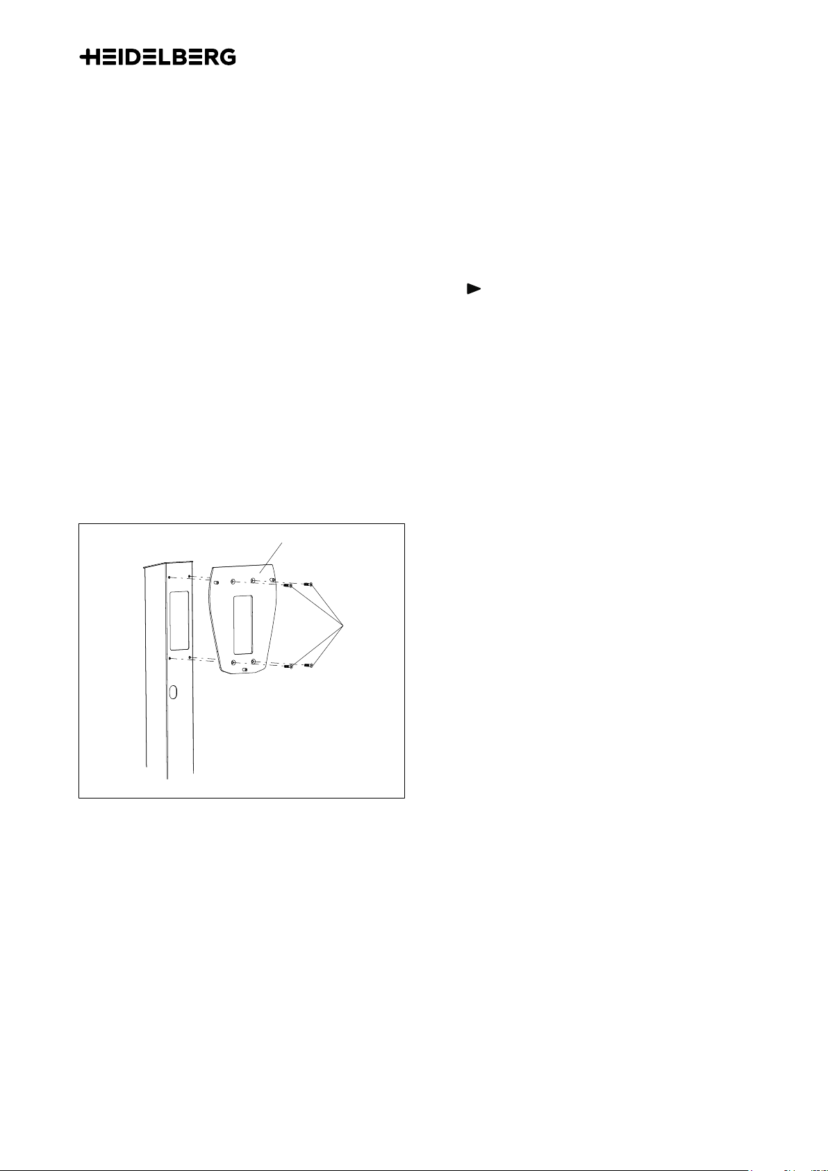
● Adapterplatte,
● Vier Senkkopfschrauben M6x16 zur Befestigung
der Adapterplatte an der Stele,
● Drei Muttern M8 zur Befestigung der Wallbox an
der Stele,
Montageanleitung
A.1.2