THERA-Trainer TT-SENS-14-01 User manual
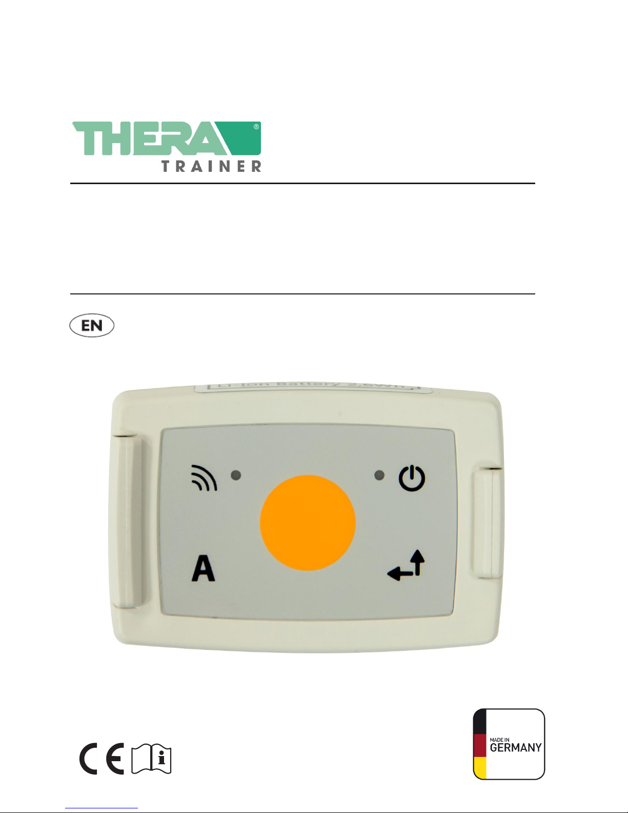
FEEDBACK SENSOR INCL. TOUCH KEY
(MODEL: TT-SENS-14-01)
USER MANUAL
English translation of original user manual

2
Art. no.: A003-928_Rev 01
Last edited: CW40/2014
FEEDBACK SENSOR INCL. TOUCH KEY
USER MANUAL
Congratulations!
You've made a great choice by purchasing this feedback sensor incl. touch key. This innovative feedback
sensor incl. touch key delivers maximum performance –Made in Germany.
This user manual will help you get to know your feedback sensor incl. touch key better. It takes you
safely through the functions and use of your new feedback sensor incl. touch key, and also offers plenty
of tips and advice for getting the most out of it.
Before using the feedback sensor incl. touch key for the first time, please read chapter 2 "Safety and
dangers".
If you have any further questions or comments, your trained specialised dealer will be happy to help.
We hope you will enjoy keeping active with your feedback sensor incl. touch key.

FEEDBACK SENSOR INCL. TOUCH KEY
USER MANUAL
Art. no.: A003-928_Rev 01
Last edited: CW40/2014
3
1 USER GUIDE. . . . . . . . . . . . . . . . . . . . . . . . . . . . . . . . . . . . . . . . . . . . . . . . . . . . . . . . . . . . . . .4
1.1 Warning notices . . . . . . . . . . . . . . . . . . . . . . . . . . . . . . . . . . . . . . . . . . . . . . . . . . . . . . . . . . . . . . . . 4
1.2 Notes . . . . . . . . . . . . . . . . . . . . . . . . . . . . . . . . . . . . . . . . . . . . . . . . . . . . . . . . . . . . . . . . . . . . . .4
1.3
Symbols in the user manual . . . . . .
.
.
.
.
.
.
.
.
.
.
.
.
.
.
.
.
.
.
.
.
.
.
.
.
.
.
.
.
.
.
.
.
.
.
.
.
.
.
.
.
.
.
.
.
.
.
4
1.4 Symbols on the product . . . . . . . . . . . . . . . . . . . . . . . . . . . . . . . . . . . . . . . . . . . . . . . . . . . . . . . . .5
2 SAFETY AND DANGERS . . . . . . . . . . . . . . . . . . . . . . . . . . . . . . . . . . . . . . . . . . . . . . . . . . . . . . 6
3 INTENDED USE . . . . . . . . . . . . . . . . . . . . . . . . . . . . . . . . . . . . . . . . . . . . . . . . . . . . . . . . . . . . . 7
3.1 Training . . . . . . . . . . . . . . . . . . . . . . . . . . . . . . . . . . . . . . . . . . . . . . . . . . . . . . . . . . . . . . . . . . 7
3.2 Biocompatibility . . . . . . . . . . . . . . . . . . . . . . . . . . . . . . . . . . . . . . . . . . . . . . . . . . . . . . . . . . . . . . 7
4 FORSEEABLE MISUSE . . . . . . . . . . . . . . . . . . . . . . . . . . . . . . . . . . . . . . . . . . . . . . . . . . . . . . 8
4.1 Misuse . . . . . . . . . . . . . . . . . . . . . . . . . . . . . . . . . . . . . . . . . . . . . . . . . . . . . . . . . . . . . . . . . . . 8
5 SCOPE OF DELIVERY AND EQUIPMENT . . . . . . . . . . . . . . . . . . . . . . . . . . . . . . . . . . . . . . . . 8
5.1 Scope of delivery . . . . . . . . . . . . . . . . . . . . . . . . . . . . . . . . . . . . . . . . . . . . . . . . . . . . . . . . . . . . . 8
5.2 Basic equipment . . . . . . . . . . . . . . . . . . . . . . . . . . . . . . . . . . . . . . . . . . . . . . . . . . . . . . . . . . . . . . 8
5.3 Options . . . . . . . . . . . . . . . . . . . . . . . . . . . . . . . . . . . . . . . . . . . . . . . . . . . . . . . . . . . . . . . . . .
5.4 Removable parts . . . . . . . . . . . . . . . . . . . . . . . . . . . . . . . . . . . . . . . . . . . . . . . . . . . . . . . . . . . . . .
6 OVERVIEW. . . . . . . . . . . . . . . . . . . . . . . . . . . . . . . . . . . . . . . . . . . . . . . . . . . . . . . . . . . . . . . . 10
7 STARTUP . . . . . . . . . . . . . . . . . . . . . . . . . . . . . . . . . . . . . . . . . . . . . . . . . . . . . . . . . . . . . . . . . 11
7.1 Fixing the feedback sensor to the THERA-Trainer balo . . . . . . . . . . . . . . . . . . . . . . . . . . . . . . 11
7.2 Fixing the feedback sensor to the THERA-Trainer coro . . . . . . . . . . . . . . . . . . . . . . . . . . . . . . . .
7.3 Plugging in Bluetooth receiver for sensors . . . . . . . . . . . . . . . . . . . . . . . . . . . . . . . . . . . . . . . . .
7.4 Switching on THERA-Trainer software . . . . . . . . . . . . . . . . . . . . . . . . . . . . . . . . . . . . . . . . . . . .
8 OPERATION . . . . . . . . . . . . . . . . . . . . . . . . . . . . . . . . . . . . . . . . . . . . . . . . . . . . . . . . . . . . . . . 11
8.1 Charging the battery . . . . . . . . . . . . . . . . . . . . . . . . . . . . . . . . . . . . . . . . . . . . . . . . . . . . . . . . . 11
8.2 Switching on/off the feedback sensor incl. touch key. . . . . . . . . . . . . . . . . . . . . . . . . . . . . . . . 13
8.3 Establishing a connection . . . . . . . . . . . . . . . . . . . . . . . . . . . . . . . . . . . . . . . . . . . . . . . . . . . . . 13
8.4 Error indicators . . . . . . . . . . . . . . . . . . . . . . . . . . . . . . . . . . . . . . . . . . . . . . . . . . . . . . . . . . . . . 14
9 TROUBLESHOOTING . . . . . . . . . . . . . . . . . . . . . . . . . . . . . . . . . . . . . . . . . . . . . . . . . . . . . . . . 14
10 CLEANING AND DISINFECTION . . . . . . . . . . . . . . . . . . . . . . . . . . . . . . . . . . . . . . . . . . . . . . 15
11 MAINTENANCE AND REPAIRS . . . . . . . . . . . . . . . . . . . . . . . . . . . . . . . . . . . . . . . . . . . . . . . 16
11.1 Maintenance . . . . . . . . . . . . . . . . . . . . . . . . . . . . . . . . . . . . . . . . . . . . . . . . . . . . . . . . . . . . . . . 16
11.2 Further use . . . . . . . . . . . . . . . . . . . . . . . . . . . . . . . . . . . . . . . . . . . . . . . . . . . . . . . . . . . . . . . . 16
12 TECHNICAL DATA . . . . . . . . . . . . . . . . . . . . . . . . . . . . . . . . . . . . . . . . . . . . . . . . . . . . . . . . . 17
13 DISPOSAL . . . . . . . . . . . . . . . . . . . . . . . . . . . . . . . . . . . . . . . . . . . . . . . . . . . . . . . . . . . . . . . 17
14 NOTES ON ELECTROMAGNETIC COMPATIBILITY OF THE FEEDBACK SENSOR
INCL. TOUCH KEY . . . . . . . . . . . . . . . . . . . . . . . . . . . . . . . . . . . . . . . . . . . . . . . . . . . . . . . . . 18
14.1 Electromagnetic emissions . . . . . . . . . . . . . . . . . . . . . . . . . . . . . . . . . . . . . . . . . . . . . . . . . . . . 18
14.2 Electromagnetic immunity . . . . . . . . . . . . . . . . . . . . . . . . . . . . . . . . . . . . . . . . . . . . . . . . . . . .
14.3 User Information acc. to FCC15.21 . . . . . . . . . . . . . . . . . . . . . . . . . . . . . . . . . . . . . . . . . . . .
14.4 Statement for Class B digital device acc.to FCC 15.105 . . . . . . . . . . . . . . . . . . . . . . . . . . . . .
14.5 Statement acc. RSS Gen Issue 3, Sect. 7.1.3 . . . . . . . . . . . . . . . . . . . . . . . . . . . . . . . .19
15 WARRANTY . . . . . . . . . . . . . . . . . . . . . . . . . . . . . . . . . . . . . . . . . . . . . . . . . . . . . . . . . . . . . . . . 20
4
4
4
4
5
6
7
7
7
8
8
8
8
8
9
9
10
11
11
12
13
13
13
13
16
16
17
17
18
19
19
19
20
20
21
21
22
23
23
23
23

4
Art. no.: A003-928_Rev 01
Last edited: CW40/2014
FEEDBACK SENSOR INCL. TOUCH KEY
USER MANUAL
1 USER GUIDE
The user manual and product are marked with a variety of symbols. These
symbols and their functions help you to use the product safely and efficiently
1.1 Warning notices
Warning categories
Warnings have different signal words depending on the type of danger:
Caution warns of the risk of material damage.
Warning warns of the risk of physical injury.
Danger warns of the risk of fatal injury.
Structure of warnings
Type and source of danger!
Action to avoid the danger.
Signal words
1.2 Notes
Information on the efficient use of the product.
1.3 Symbols in the user manual
Instructions
Structure of instructions:
►Instruction to do something.
Presentation of results if required.
Lists
Structure of non-numbered lists:
List level 1
–List level 2
Structure of numbered lists:
1. List level 1
2. List level 1
2.1 List level 2
2.2 List level 2
Note
Art. no.: A003-928_Rev 01
Last edited: CW40/2014
5
FEEDBACK SENSOR INCL. TOUCH KEY
USER MANUAL
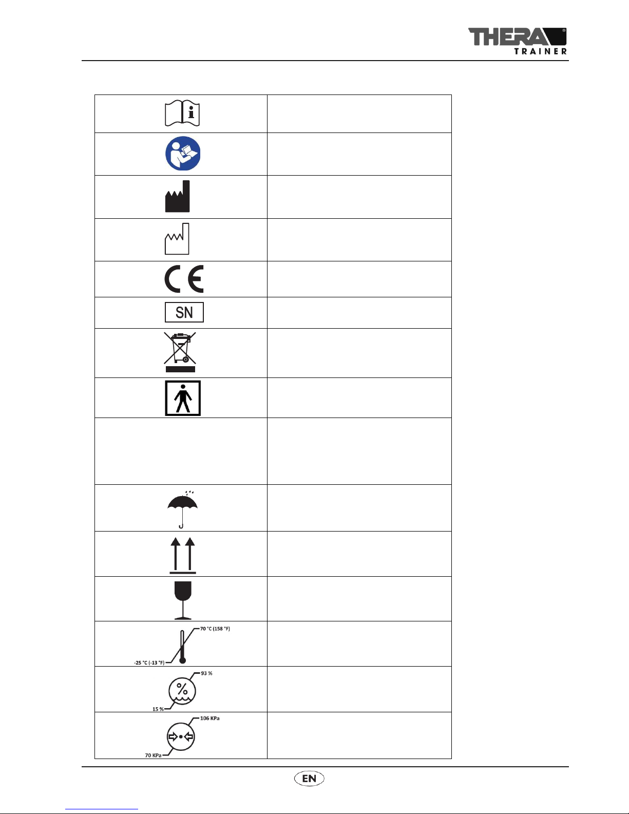
1.4 Symbols on the product
User manual
Follow the user manual!
Manufacturer
Date of manufacture
Market launch in accordance with Medical
Devices Directive 93/42/EEC
Serial number
Disposal:
Do not dispose of the product in
household waste. Dispose of the product
in accordance with local regulations.
Type BF medical device
IP22
Protection against solid foreign objects
with a diameter greater than 12.5 mm.
Protection against dripping water when
the feedback sensor incl. touch key is
tilted up to 15° (only in combination with
the sensor holder).
Protect product from humidity.
This side up
Caution fragile
Temperature limit:
Between -25 °C (-13 °F) and +70 °C
(+158 °F)
Humidity limit:
Between 15 % and 93 % Rh
Air pressure limit:
Between 70 KPa and 106 KPa

6
Art. no.: A003-928_Rev 01
Last edited: CW40/2014
FEEDBACK SENSOR INCL. TOUCH KEY
USER MANUAL
2 SAFETY AND DANGERS
Observe the user manual.
If the user has a cardiac pacemaker, consult a doctor before the first training
session and observe emissions.
Do not use the feedback sensor incl. touch key in wet, humid or hot
environments.
Make sure that the feedback sensor incl. touch key does not get wet.
Only use the USB charger approved by the manufacturer.
Only use the USB charger for the feedback sensor with the correct supply
voltage.
Exclusively use the USB charging cable supplied by the manufacturer.
Exclusively charge the feedback sensor incl. touch key outside the immediate
patient surrounding (1.5 metres).
Ensure that the feedback sensor incl. touch key connected to the THERA-
Trainer software is clipped to the correct THERA-Trainer.
The maximum range of movement must not overstrain the user.
Only use the feedback sensor incl. touch key if in good and functional
condition.
In case of damage, malfunctions, etc., of the feedback sensor incl. touch
key, contact a trained dealer immediately.
Only use the feedback sensor incl. touch key if the USB charging cable is
undamaged and in proper working order.
Disinfect the feedback sensor incl. touch key before every training session.
Leave the feedback sensor incl. touch key at room temperature for 1 hour
before using it for the first time.
Have exclusively trained dealers done any repair work.
The battery in the feedback sensor incl. touch key may only be replaced by a
trained dealer.
The feedback sensor incl. touch key may only be opened by a trained dealer
and only modified after consultation with the manufacturer.
Faulty/damaged batteries are not suitable for transport. These must be
disposed of in accordance with national regulations.
The feedback sensor incl. touch key must not be returned to the manufacturer
with a faulty/damaged battery.

Art. no.: A003-928_Rev 01
Last edited: CW40/2014
7
FEEDBACK SENSOR INCL. TOUCH KEY
USER MANUAL
Note
3 INTENDED USE
The feedback sensor incl. touch key:
is used for wireless transmission of the inclination data to a control and
display unit. The biofeedback illustrations of appropriate THERA-Trainer
software are controlled on the basis of this inclination data.
The feedback sensor incl. touch key is used together with the suitable THERA-
Trainer software and a control and display unit to mobilise persons with limited
mobility with help of exercises.
Observe the indications of the THERA-Trainer and THERA-Trainer software being
used.
User
Persons who have been instructed by expert staff on how to use the
feedback sensor incl. touch key and are thus authorised to operate and
exercise with the feedback sensor incl. touch key.
The user is entirely responsible for the safe and correct use of the feedback
sensor incl. touch key.
Specialised staff
Persons who gained their skills and expertise by means of professional
training in the medical or medical-technical sector (e.g. doctors, therapists,
specialist dealers).
Persons who due to their professional experience and by means of
instruction/training by the manufacturer are able to assess safety-relevant
regulations and recognise potential risks in their field of work (e.g.
assistants).
To guarantee safe use of the feedback sensor incl. touch key, train expert
staff regularly.
3.1 Training
Before initial startup:
Have training
- By dealers, doctors or therapists trained by the manufacturer.
- Using this user manual.
Check with doctors or therapists whether training without supervision is
possible with the feedback sensor incl. touch key.
Have an assistant trained by dealers, doctors or therapists trained by the
manufacturer.
3.2 Biocompatibility
All components of the feedback sensor incl. touch key the user will touch when
using the unit as intended are designed to meet the biocompatibility requirements
of the applicable standards.
For any questions, contact a trained dealer.

8
Art. no.: A003-928_Rev 01
Last edited: CW40/2014
FEEDBACK SENSOR INCL. TOUCH KEY
USER MANUAL
4 FORSEEABLE MISUSE
The feedback sensor incl. touch key is not used for:
Diagnosis
Monitoring
Measuring
4.1 Misuse
Do not use the feedback sensor incl. touch key in:
Combination with other products emitting ionising radiation (e.g. radiation
therapy, nuclear medicine, etc.)
Rooms containing
–Explosive substances
–Oxygenated air
The presence of
–Flammable anaesthetics
–Volatile solvents
Devices not approved by the manufacturer.
Combination with wireless communications devices such as wireless home
network devices (WLAN, WiFi), mobile phones, cordless phones and their
base stations, or other hands-free kits, etc. These can influence the device
and should therefore be kept at a distance of 3.8 m.
5 SCOPE OF DELIVERY AND EQUIPMENT
The feedback sensor incl. touch key comes with individual options. This user
manual describes all options available for the feedback sensor incl. touch key.
Depending on the model, the user manual may include options not featured by
the feedback sensor incl. touch key. If the feedback sensor incl. touch key
features options are not described in the user manual, an appendix will be
included.
5.1 Scope of delivery
The delivery note contains all information about the scope of delivery.
5.2 Basic equipment
Basic equipment of the feedback sensor incl. touch key:
Feedback sensor incl. touch key
USB charging cable
Bluetooth receiver for sensors
Feedback sensor mounting kit for
- THERA-Trainer balo
- OR -
- THERA-Trainer coro
User manual Feedback sensor incl. touch key
Art. no.: A003-928_Rev 01
Last edited: CW40/2014
9
FEEDBACK SENSOR INCL. TOUCH KEY
USER MANUAL
Note
5.3 Options
Available option:
USB charger for feedback sensor
The feedback sensor incl. touch key can only be used in combination with the
suitable THERA-Trainer software, a control and display unit, and a Bluetooth
receiver for sensors.
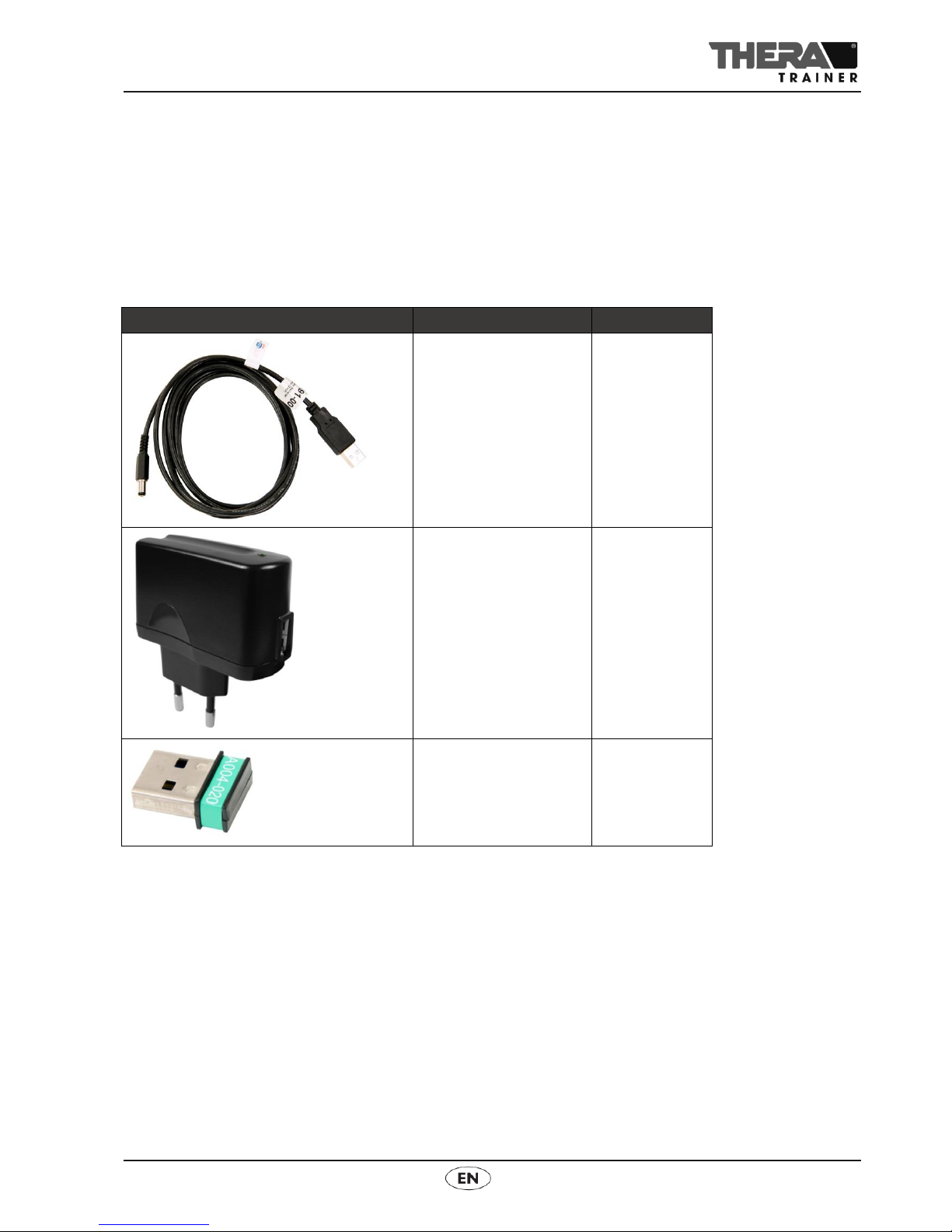
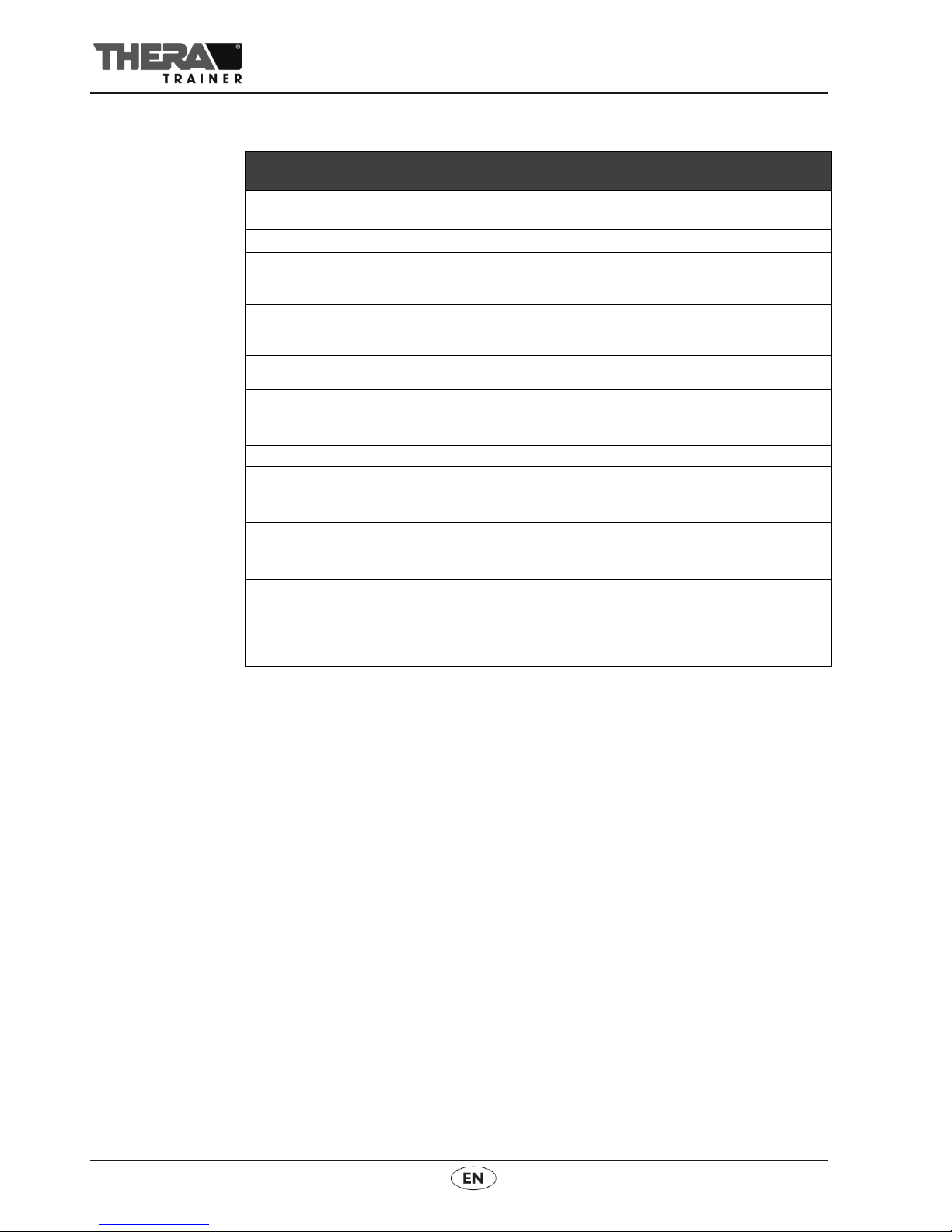
5.4Removable parts
Name
Article no.
USB charging cable
A003-891
USB charger for
feedback sensor
A003-980
Bluetooth receiver for
sensors
A004-020

10
Art. no.: A003-928_Rev 01
Last edited: CW40/2014
FEEDBACK SENSOR INCL. TOUCH KEY
USER MANUAL
6 OVERVIEW
(1) Sensor orientation
(2) Touch key with touch pad
(3) Sensor detection (here feedback sensor incl. touch key Type A)
(4) Socket for USB charging cable
(5) Feedback sensor incl. touch key (applied part Type BF)
(6) Connection status indicator
(7) Activation/charge status indicator
(8) Sensor holder
4 3 2 1
5 6 7 8

Art. no.: A003-928_Rev 01
Last edited: CW40/2014
11
FEEDBACK SENSOR INCL. TOUCH KEY
USER MANUAL
7 STARTUP
To use the feedback sensor incl. touch key for the first time, remove it from
its packaging and check for damage caused in transit.
Check if delivery is complete.
Report any damage to the supplier or carrier without delay.
Before using the equipment for the first time, charge the battery for at least 6
hours.
7.1 Fixing the feedback sensor to the THERA-Trainer balo
Fix the feedback sensor incl. touch key to a THERA-Trainer balo using the
feedback sensor mounting kit for the THERA-Trainer balo. To fix it, follow the
instructions below:
►Mount the sensor holder 1 to the system bracket 3 with two bolts 2, using a
suitable tool.
- Fix the sensor holder on the system bracket using the correct orientation
(wider side facing left).
- Insert two bolts through the holes and secure each one with a nut.
►Bolt the system bracket 3to the swivel plate under the table unit of the
THERA-Trainer balo (left-hand side) 5with a suitable tool using two bolts 4.
►Clip the feedback sensor incl. touch key 6into the sensor holder 1.
- Ensure that the sensor orientation arrows 7point forward and upward.
1 2 3 4 4
5
4
1
3
6
7
1 2 3 4 4

12
Art. no.: A003-928_Rev 01
Last edited: CW40/2014
FEEDBACK SENSOR INCL. TOUCH KEY
USER MANUAL
7.2 Fixing the feedback sensor to the THERA-Trainer coro
Fix the feedback sensor incl. touch key to a THERA-Trainer coro using the
feedback sensor mounting kit for the THERA-Trainer coro. To fix it, follow the
instructions below:
►Mount the sensor holder 4 to the system bracket 2 with two bolts 3, using a
suitable tool.
- Fix the sensor holder on the system bracket using the correct orientation
(wider side facing left).
- Insert two bolts through the holes and secure each one with a nut.
►Mount the sensor holder 2 on the height adjustment clamp 5 on the THERA-
Trainer coro (right-hand side) with two bolts 1, using a suitable tool.
►Clip the feedback sensor incl. touch key 6into the sensor holder 4.
- Ensure that the sensor orientation arrows 7point forward and upward.
1 2 3 4
5
2
4
6
5
1
6
7
5
6
7
1
Art. no.: A003-928_Rev 01
Last edited: CW40/2014
13
FEEDBACK SENSOR INCL. TOUCH KEY
USER MANUAL
The feedback sensor incl. touch key is fitted with a maintenance-free rechargeable
lithium-ion 3.6 V/680 mAh battery.
Caution
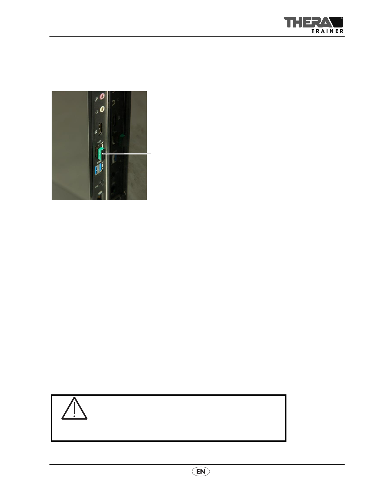
7.3 Plugging in Bluetooth receiver for sensors
►Before switching on the THERA-Trainer software, the Bluetooth receiver for
sensors 1must be plugged into a free USB interface on the control and
display unit.
If the Bluetooth receiver is first inserted after the THERA-Trainer software has
been switched on, it will be unable to make a connection to the feedback sensor
incl. touch key.
If the Bluetooth receiver for sensors is pulled out while the THERA-Trainer
software is turned on, the connection to the THERA-Trainer software will be
interrupted and can only be restored by restarting.
7.4 Starting THERA-Trainer software
►Switch on control and display unit.
►THERA-Trainer software starts automatically.
When the feedback sensor incl. touch key is then switched on, a connection is
established. The feedback sensor incl. touch key is now ready for operation.
The user manual for the THERA-Trainer software and control and display unit
must be observed when using the feedback sensor incl. touch key.
This ensures that the feedback sensor incl. touch key connects to the right
system (control and display unit with THERA-Trainer software). Two systems
should never be started at the same time.
8 OPERATION
8.1 Charging the battery
C
V
Incorrect use will result in damage!
Handle batteries with care.
Do not open the batteries.
Protect batteries from extreme heat or fire.
Always have the battery replaced by a trained dealer
Note
Note
1
14
Art. no.: A003-928_Rev 01
Last edited: CW40/2014
FEEDBACK SENSOR INCL. TOUCH KEY
USER MANUAL
Caution
Warning
The feedback sensor incl. touch key is supplied with a USB charging cable as
standard. This can be used to charge the battery from a USB interface (computer,
control and display unit, etc.) without a feedback sensor USB charger.
Do not use within 1.5 metres of the direct surrounding of the patient.
►Only use USB chargers recommended by the manufacturer.
Standard USB charger for feedback sensor:
Available from the manufacturer as an option.
- Is not a medical-device USB charger for the feedback sensor.
- Do not use within 1.5 metres of the direct surrounding of the patient.
Use a commercially-available USB charger (with CE marking).
- 5 V (d.c.)/0.5 A
- USB connection
- Do not use within 1.5 metres of the direct surrounding of the patient.
The service life of the battery depends on its charging/discharging cycles and
storage temperature.
Possible energy performance of batteries:
Approx. 1,000 partial discharges
The feedback sensor incl. touch key is fitted with over-discharge protection
for the battery.
When the battery is discharged:
When the remaining charge (based on the capacity still available) is under
30 %, the activation/charge status LED will flash green-orange.
When the remaining charge (based on the capacity still available) is under
15 %, the activation/charge status LED will flash orange.
If the battery is fully discharged, the activation/charge status LED will be off.
An operating period of approx. 10 hours per charging cycle can be obtained
depending on the conditions of use.
The battery capacity will decline over time.
The manufacturer recommends having the battery replaced by a trained dealer
after 2 to 3 years, depending on the number of charging cycles.
Faulty USB charging cable connection due to USB cable
being plugged in incorrectly!
Make sure that the USB charging cable plug is correctly
positioned in the charging socket when it is connected.
Observe position of plug.
Only use a USB charging cable approved by the
manufacturer.
Using an unsuitable USB charging cable or USB charger is a
fire hazard!
Only use a USB charging cable and USB charger for
feedback sensor approved by the manufacturer.
USB Charging
cable
USB charger
Operating
period
Charging
requirements
Operating time
Note
Charging
process

Art. no.: A003-928_Rev 01
Last edited: CW40/2014
15
FEEDBACK SENSOR INCL. TOUCH KEY
USER MANUAL
Charging the battery:
►Remove the feedback sensor incl. touch key from the sensor holder.
►Switch off the feedback sensor incl. touch key before charging (see chapter
8.2).
►Ensure that the feedback sensor incl. touch key is switched off while
charging.
►Plug the charging cable into the charging socket in the feedback sensor incl.
touch key.
►Insert the USB plug of the USB charging cable into a free USB interface.
OR
►Insert the USB plug of the USB charging cable in the USB interface of the
USB charger for the feedback sensor.
►Insert the plug of the USB charger for the feedback sensor into the socket.
The USB charging cable and USB charger for the feedback sensor available
optionally from the manufacturer are not a medical-device USB charging cable and
USB charger. Charging must take place outside a 1.5-metre radius of the direct
surrounding of the patient.
Charging process begins.
The LED of the charge/activation status indicator shows the status of the
charging process.
LED flashes green:
Battery charging.
LED lights green:
Battery is fully charged.
During the charging phase of the battery, the feedback sensor incl. touch key is
inoperable and therefore cannot be used for training.
Batteries are leak-proof if handled and stored correctly.
►Store the battery in a cool place if not used for an extended period.
►Have batteries replaced exclusively by a trained dealer.
►To have batteries replaced, contact a trained dealer.
When batteries are replaced by a trained dealer, dispose of them in accordance
with national regulations.
The battery warranty is subject to legal regulations:
24 months
- 6 months full warranty
- 18 months with reversal of burden of proof
Note
Note
Storage
Replacing the
battery
Disposal
Warranty

16
Art. no.: A003-928_Rev 01
Last edited: CW40/2014
FEEDBACK SENSOR INCL. TOUCH KEY
USER MANUAL
8.2 Switching on/off the feedback sensor incl. touch key
To switch the feedback sensor incl. touch key on:
►The battery must be charged.
►Press the touch key until the activation/charge status indicator shows a
status.
The LED of the charge/activation status indicator lights up green.
The feedback sensor incl. touch key is trying to establish a connection with the
control and display unit.
►The LED of the connection status indicator flashes green while the
connection with the control and display unit is being established.
►When the LED of the connection status indicator lights up with a steady
green, a connection has been established.
To switch the feedback sensor incl. touch key off:
►Press the touch key until the activation/charge status indicator doesn't show
the status.
The LED of the charge/activation status indicator will turn off.
8.3 Establishing a connection
After the feedback sensor incl. touch key has been switched on, a wireless
connection is established between the feedback sensor incl. touch key and the
control and display unit.
In order to establish a wireless connection, a Bluetooth receiver for the sensors
must be plugged into the control and display unit. Only use the Bluetooth receiver
for sensors approved by the manufacturer (article no. A004-020).
If a different Bluetooth receiver is used, no wireless connection can be established.
The LED of the connection status indicator indicates the following status:
LED flashes green:
A connection is being established between the feedback sensor incl. touch
key and the control and display unit.
This can take several seconds.
If a connection cannot be established, the feedback sensor automatically
switches off after approx. 3 minutes.
►Check whether the feedback sensor incl. touch key is too far away from
the control and display unit.
- The wireless connection has a range of about 5 metres.
►Check whether the control and display unit is switched on.
►Check whether a Bluetooth receiver for sensors is plugged into the
control and display unit for the wireless connection.
►Check whether the correct Bluetooth receiver for sensors is plugged in
(article no. A004-020).
►Ensure the correct Bluetooth receiver for sensors is plugged in before
starting the THERA-Trainer software.
LED lights green:
A connection is being established between the feedback sensor incl. touch
key and the control and display unit.
Switching on
Switching off
Note

Art. no.: A003-928_Rev 01
Last edited: CW40/2014
17
FEEDBACK SENSOR INCL. TOUCH KEY
USER MANUAL
8.4 Error indicators
The feedback sensor incl. touch key can display the following error states:
LED of the connection status indicator flashes red:
A system error has occurred.
- see chapter 9 "Troubleshooting"
LED of the activation/charge status indicator alternately flashes green and orange:
The remaining battery charge is under 30 %.
Charge the battery.
- see the chapter "Charging the battery"
LED of the activation/charge status indicator flashes orange:
The remaining battery charge is under 15 %.
Charge the battery.
- see the chapter "Charging the battery"
9 TROUBLESHOOTING
If a system fault occurs in the feedback sensor incl. touch key, the LED connection
status indicator flashes red. The control and display unit shows the error code.
Observe the user manual for the relevant THERA-Trainer software.
The software version of the feedback sensor incl. touch key is required for
troubleshooting. This is shown as follows:
►Feedback sensor incl. touch key is turned on.
►Press the touch key 2until the feedback sensor incl. touch key switches off
and the LED activation/charge indicator 3is on again.
►Stop pressing the touch key.
►The touch key lights up once.
- The software version is displayed.
►The connection status indicator 1 lights up successively to indicate the first
figure (e.g 3 times).
►The touch key lights up once.
- This means that second figure will now be shown.
►The activation/charge indicator 3 lights up successively to indicate the
second figure (e.g. 5 times).
►The touch key lights up once again.
- The software version display process has finished.
This example shows software version 3.5.
1 2 3
Software
version

18
Art. no.: A003-928_Rev 01
Last edited: CW40/2014
FEEDBACK SENSOR INCL. TOUCH KEY
USER MANUAL
Danger
Caution
10 CLEANING AND DISINFECTION
Risk of infection due to contaminated accessories/options!
Disinfect after each use.
Wear gloves for cleaning and disinfection.
Warning
Material damage due to incorrect cleaning or disinfection!
Never use cleaning agents that are aggressive, abrasive or
caustic, or contain solvents.
Use exclusively mild and environment-friendly cleaning
agents and disinfectants.
Use exclusively disinfectants that conform to country-specific
regulations.
Observe safety instructions by manufacturers of cleaning
agents and disinfectants.
Danger to life due to electric shock!
Always switch off the feedback sensor incl. touch key before
cleaning and disinfecting.
The charging process must always be finished and the
feedback sensor incl. touch key must always be disconnected
from the mains before cleaning and disinfecting.
Make sure that no cleaning agent or disinfectant gets into the
feedback sensor incl. touch key.
If any cleaning agent or disinfectant gets into the feedback
sensor incl. touch key, contact a trained dealer immediately.
Clean/disinfect the feedback sensor incl. touch key as follows:
Switch off the feedback sensor incl. touch key.
Stop the charging process and disconnect the feedback sensor incl. touch
key from the mains.
Check electronic components for damage.
- If any damage is found, do not clean but contact trained dealer.
Make sure that the room is sufficiently aired during cleaning or disinfection.
Clean the surface of the feedback sensor incl. touch key with a soft, damp
cloth.
When cleaning surfaces of the feedback sensor incl. touch key, only use
disinfectants approved under national regulations.
Clean foils and stickers with care.
Let the feedback sensor incl. touch key dry properly.
Switch on the feedback sensor incl. touch key.
Art. no.: A003-928_Rev 01
Last edited: CW40/2014
19
FEEDBACK SENSOR INCL. TOUCH KEY
USER MANUAL
11 MAINTENANCE AND REPAIRS
11.1 Maintenance
The feedback sensor incl. touch key is maintenance-free.
The manufacturer recommends having replaced the battery in the feedback sensor
by a trained dealer after 2 to 3 years, depending on the number of charging
cycles.
11.2 Further use
The feedback sensor incl. touch key is suitable for further use by a different
customer.
Before the feedback sensor incl. touch key is reused:
Clean and disinfect thoroughly (see chapter 10 Cleaning and
disinfection).
Perform a visual check or a function check.
Check if all accessories and options are complete (see delivery note).
Danger to life due to electric shock!
Switch off the feedback sensor incl. touch key before all
maintenance and servicing work.
Stop the charging process before all maintenance and
servicing work and disconnect the feedback sensor from the
mains.
Only allow trained dealers to carry out this work.
Danger
Note
20
Art. no.: A003-928_Rev 01
Last edited: CW40/2014
FEEDBACK SENSOR INCL. TOUCH KEY
USER MANUAL
12 TECHNICAL DATA
13 DISPOSAL
To dispose of the feedback sensor incl. touch key:
Observe country-specific regulations and specifications.
Dispose of metal parts as scrap metal.
Dispose of plastic parts as prescribed, depending on the type of material.
Dispose of electric and electronic components as electronic scrap.
Dispose of lithium-ion batteries in accordance with national rules and
regulations.
- Do not dispose of lithium ion batteries unless the positive and negative
poles have been taped up.
Feedback sensor incl. touch key
Dimensions:
l x w x h
approx. 7.5 cm x 5.5 cm x 2.5 cm
Weight:
approx 80 g
Protection category:
IP22
(only if the feedback sensor incl. touch key is attached to the
sensor holder)
Mains supply USB
charger for feedback
sensor
100-240 V~, 50/60 Hz
USB charger voltage for
feedback sensor
5 V
USB charger current for
feedback sensor
0.5 A
Lithium-ion battery
3.6 V/680 mAh
Nominal battery energy
2.65 Wh
Ambient conditions for
use
5 °C to 40 °C
15 % to 93 % Rh
700 to 1060 hPa
Ambient conditions for
transport/delivery
-25 °C to 70 °C
15 % to 93 % Rh
700 to 1060 hPa
Materials used:
Plastic (ABS), silicone, rechargeable lithium-ion battery
Operational life:
Feedback sensor
incl. touch key
7 years
(not including the battery)
Table of contents


