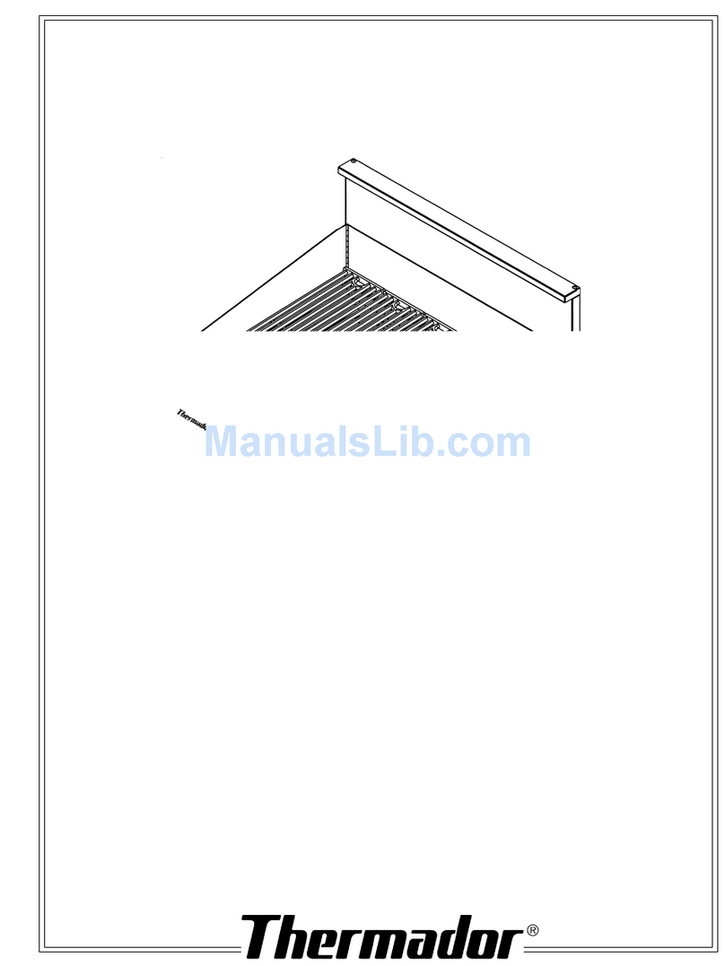
Thermador PB30 User manual

F
o
r
T
h
e
r
m
a
d
o
r®
P
r
o
f
e
s
s
i
o
n
a
l
Indoor Grill
INSTALLATION
INSTRUCTIONS
Model
PB30

Section 1: Safety Information
TESTED IN ACCORDANCE WITH ANSI Z21.1
CURRENT ISSUE, THE STANDARD FOR
HOUSEHOLD COOKING GAS APPLIANCES.
Check your local building codes for the proper
methodofinstallation.Intheabsenceoflocalcodes,
this unit should be installed in accordance with the
National Fuel Gas Code No. Z223.1/NFPA54-cur-
rent issue and the National Electrical Code ANSI/
NFPA70-current issue.
IMPORTANT
Localcodesvary.Installation,gasconnections
andgroundingmustcomplywithallapplicable
codes.
WARNING
Disconnectpowerbeforeinstalling.Beforeturning
powerON,besurethatallcontrolsareintheOFF
position.
WARNING:
If the information in this manual is not
followed exactly, a fire or explosion may
result causing property damage, personal
injury or death.
— Do not store or use gasoline or other flam-
mablevaporsandliquidsinthevicinityofthis
or any other appliance.
— WHAT TO DO IF YOU SMELL GAS
■Do not try to light any appliance.
■Do not touch any electrical switch.
■Do not use any phone in your building.
■Immediately call your gas supplier from a
neighbor’s phone. Follow the gas supplier’s
instructions.
■Ifyoucannotreachyourgassupplier,callthe
fire department.
— Installation and service must be performed
by a qualified installer, service agency or the
gas suppler.
TO REDUCE THE RISK OF TIPPING OF THE
APPLIANCE, IT MUST BE SECURED BY A
PROPERLY INSTALLED ANTI-TIP DEVICE.
VERIFYTHATTHEANTI-TIPDEVICEISENGAGED
PER INSTALLATION IN–STRUCTIONS. (NOTE:
ANTI-TIP DEVICE IS REQUIRED ON ALL 30"
AND 36" RANGES)
!
WARNING
■ ALL RANGES CAN TIP
■ INJURY TO PERSONS
COULD RESULT
■ INSTALL ANTI-TIP DEVICE
■ SEE INSTALLATION
INSTRUCTIONS
For Massachusetts Installations:
1.Installationmustbeperformedbyaqualified
or licensed contractor, plumber or gas fitter
qualified or licensed by the state, province
or region where this appliance is being in-
stalled.
2. Shut-off valve must be a “T” handle gas
cock.
3. Flexible gas connector must not be longer
than 36 inches.
Note: Thisgrill isNOTdesigned forinstallation
in manufactured (mobile) homes or for installa-
tion in Recreational Park Trailers.

NATURAL GAS REQUIREMENTS -
Inlet Connection: 1/2" or 3/4" NPT
Supply Pressure: 6" to 14" W.C.
(14.9 mB to 34.9 mB)
Manifold Pressure: 5" W.C. (12.5 mB)
PROPANE GAS REQUIREMENTS -
Inlet Connection: 1/2" or 3/4" NPT
Supply Pressure: 11" to 14" W.C.
(27.4 mB to 34.9 mB)
Manifold Pressure: 10" W.C. (24.9 mB)
SECTION 2: GAS REQUIREMENTS
INTRODUCTION
The Thermador Professional Indoor Grill is built-in
appliance with two burners rated at 20,000 BTU/HR
each
The total gas consumption of the Thermador Profes-
sional®Indoor Grill with all burners on "HI" is 40,000
BTU/HR.
Installer: Please leave these instructions with the unit for the owner.
Owner: Please retain these instructions for future reference.
Figure 1 - Model PB30BS
IMPORTANT: A manual gas shut off valve
must be installed external to the appliance, in
a location accessible with the unit installed in
theenclosure.Makesurethevalveisturnedoff
prior to connecting the appliance.
WARNING: If the information in
this manual is not followed exactly, a
fire or explosion may result causing
property damage, personal injury or
death.
▲
!
SECTION 1:
Safety
Information ...Inside Cover
Introduction....................................................1
SECTION 2: Gas Requirements ....................1
Natural Gas Requirements.............................1
Propane Gas Requirements ...........................1
Gas Consumption Caution ............................2
Propane Hook-up Caution.............................2
SECTION 3: Cabinet Preparation........... 2 – 4
SECTION 4: Ventilation Requirements..........5
SECTION 5: Electrical Requirements
and Grounding...............................................5
Contents
SECTION 6: Unpacking, Moving and
Placing the Unit........................................6 – 7
Locating your Professional®Indoor Grill........6
Natural Gas to Liquid Propane Conversion...7
SECTION 7: Gas and Electrical Hook-up ......8
SECTION 8: Test and Adjustment.................9
Checking for Leaks.........................................9
Burner Air Adjustment ...................................9
Installer Checklist.................................... 10
Installation............................................10
Gas Supply ...........................................10
Electrical...............................................10
1

1. Determine a suitable location for the grill by
taking into account availability of gas and elec-
trical supplies. Insure that the gas supply line
and electrical supply are located in close prox-
imity to the unit to keep connections to the unit
asshortaspossibleandallowforinstallationand
removal of the unit from the enclosure. The
installer-supplied gas shut-off valve must be
installed in an easily accessible location.
2. The grill is designed to be supported below the
counterbyfouradjustablelegs.Donotallowthe
unit to hang from the countertop. The recom-
mended cabinet construction is a pair of sup-
portsthatarefastenedtotheinteriorwallsofthe
cabinet, as shown in Figure 2a and 2b. This
allows access to the legs from beneath the unit
to facilitate adjustment. Another alternative
would be to construct a platform for the unit to
sit on; however, the legs will need to be pre-
adjusted before the unit is installed in the cabi-
net. Also, an opening will need to be provided
in the left rear corner of the platform for clear-
ance of the gas supply piping and power cord.
Section 3: Cabinet Preparation
2
See Illustrations, Pages 5 and 6.
3. The grill can be installed with the front either
flush or projecting, depending on the counter
depth. See Figures 3 and 4 (next page). The
maximum depth of overhead cabinets installed
on either side of the hood is 13" (330mm).
4. Theareabelowtheremovablepanelmustopen
to provide access to clean the grease channel
and grease tray.
5. The Model GP30LBS backguard must be in-
stalled. This backguard must be ordered sepa-
rately. Attach the backguard before lowering
the unit into the final installed position.
6. Always keep appliance area clean and free of
combustiblematerials,gasolineandotherflam-
mable vapors and liquids.
7. Do not obstruct the flow of combustion and
ventilation air to the unit.
8. Below the cooking surface, combustible con-
struction can be placed directly adjacent to the
unit.
9. Theminimumhorizontal clearance from sides is
6" (153mm).
10. In all installations, do not locate this indoor grill
gas appliance under unprotected combustible
overhead construction.
CAUTION:
The appliance and its individual shut-off valve must be disconnected from the gas supply
before any pressure testing of the system at test pressures in excess of 1/2" psig (3.5kPa).
CAUTION:
The appliance must be isolated from the gas supply system by closing its individual manual
shut-off valve during any pressure testing of the gas supply piping system at test pressures
equal to or less than 1/2" psig (3.5kPa).
When checking the manifold gas pressure, the inlet pressure to the appliance regulator
should be at least 7.0" W.C. for natural gas, and 11.0" W.C. for propane.
Do not attempt any adjustment of the pressure regulator.
CAUTION:
Whenconnectingtopropanegassupply,makecertainthatthepropanegastankisequipped
with its own high pressure regulator in addition to the pressure regulator supplied with the
appliance. The pressure of the gas at the appliance regulator must not exceed 14" water
column.
Important Safety Information
▲
!

3
Figure 2a
Section 3: Cabinet Preparation Illustrations
Figure 2b
Drip Tray
Leveling Leg
Support block
Cabinet wall
must be
removable
For accessibility to
grease tray and grease
channel, cabinet doors
should extend from the
bottom of the remov-
able panel down to the
end of the cabinet base
or toe kick.
Removable Panel
➛
Grease
Channel
7-13/16"
2-13/16"
➛
➛
➛
➛
➛
➛
➛
➛
➛
➛
Front View Side View
➛
➛
13-5/16"
10-5/8"

Section 3: Cabinet Preparation Illustrations
NOTE: All height width and depth dimensions are shown in inches. All Professional
®
Indoor Grills are CSA approved.
Model No. Overall Dimensions Cutout Dimensions
AB CD EF
PB30BS 7-
13
/
16
(199mm) 29-
15
/
16
(760mm) 26-
1
/
2
(673mm) 13-
5
/
16
(338mm) 29-
5
/
8
(752mm) 22-
11
/
16
(576mm)
Professional®Indoor Grill Model PB30BS
4
Figure 3a Model PB30BS
Figure 4b.
See Detail A 3/4"
Min.
E
Figure 4a.
See Detail A
Wall Installation with
Countertop Backsplash
13"
(350mm)
Max.
36" OR 48" HOOD
Hood
Bottom to
Countertop
(762mm)
to
(914mm)
➛
➛
18" Min.
(457mm)
Figure 3b
Wall Installation
Detail A
Corner
Notch
Detail
➛
➛
➛
D
1/4" (6.4 mm)
➛
Front face of cabinet
◆➛
Refer to Detail A:
◆ =0" - Control panel projects 2" from front face of
base cabinet.
◆ =5/8" - Control panel projects 1-3/8" from front
face of base cabinet (rear of unit flush to wall with
standard 24" deep base cabinet).
◆ =2" - Control panel flush with front face of base
cabinet(min.25-3/8"deepbasecabinetrequired).
➛
F
B
A
C
➛
➛
➛
➛
30"
to
36"
Custom removable
access panel
Custom removable
access panel
➛
➛

Section 5: Electrical Requirenments and Grounding Instructions
Installationofelectricalsupplycircuitshouldbe
done by a qualified electrician in accordance
withlocalcodesandordinances.Intheabsence
oflocal codesorordinances,the supplyshould
be installed in accordance with the National
Electric Code ANSI/NFPA70-current issue.
CAUTION
It is strongly recommended that an exhaust hood be
installed above the grill. Hoods that incorporate grease
filters of mesh construction should not be used. Testing
has shown that mesh filters can collect and hold enough
grease to become a fire hazard.
Downdraft ventilation should not be used. Due to the
high heat capacity of this unit, and the smoke generated
during grilling of foods, particular attention should be
paid to the hood and ductwork installation to insure it
meets local building codes.
Due to the high volume of ventilation air required, a
source of outside replacement (make-up) air is recom-
mended. This is especially important for tightly sealed
and insulated homes.
A qualified heating and ventilating contractor should
be consulted.
Table 1 indicates the Thermador hoods, by model
number, that are recommended for use with the indoor
grill.
For wall installations, the minimum hood width is 36"
(915 mm) [3" (77 mm) overhang per side]. Where space
permits, a wider hood may be desirable for improved
ventilation performance.
For best smoke capture, the lower edge of the hood
Section 4: Ventilation Requirements
Installation Type Hood Blower
Wall PH36ZS1VTNl000Q
PH42ZS
PH48ZS
PH54ZS
Table 1
5
NOTE: Ventilation hoods and blowers are de-
signed for use with single-wall ducting. Some local
building codes may require double-wall ducting.
Before starting installation, consult local building
codesandagenciestoinsurethattheinstallationwill
meet local requirements.
Notes: 1 For wall installation where adequate space
is available, the installer or user may elect to use a
hood that is wider than the grill cooking surface.
This may be particularly beneficial for those cases,
such as a long duct run or heavy usage of the grill,
in which improved capturing of the cooking exhaust
is desired.
should be installed a minimum of 30" (762 mm) to a
maximumof36"(915mm)abovethegrillcookingsurface.
See Fig. 3b. Minimum overhang of hood to grill on either
side is 3 inches (77mm).
Three-Prong Plug and Receptacle
Figure 5.
The Thermador Professional
®
Indoor Grill uses an electronic ignition system that requires a 120 VAC, 10A, 60
Hz power supply. A properly grounded and polarized duplex outlet must be provided adjacent to the lower left
rear corner of the unit. See Figure 5.
Electrical Grounding Instructions
Thisindoorcookinggasapplianceisequipped
with a three-prong (grounding) plug for your
protectionagainstshockhazardandshouldbe
plugged directly into a properly grounded
three-prong receptacle. Do not cut or remove
the grounding prong from this plug.
WARNING

Section 6: Unpacking,Moving and Placing the Unit
Leavingtheuniton the pallet, move the unit close to the finalinstallation site. Verify the gas supply type.
Iftheunit is not compatible with thegassupply,itwillbe necessary to convert itforusewiththesupply. See
conversion instructions following.
LOCATING YOUR PROFESSIONAL®GRILL
CONVERSION KIT BY MODEL
Model No. Orifice Description Part Number Quantity Remarks
PB30BS #54 Orifice Hood, Grill Burner 5040000446 2 To Convert NG to LP
Conversion Sticker 5040001441 1
Tools/Parts Required
Socket Driver-1/4" Drive, 3" minimum extension
1/2" Deep Well Socket
1/2" Open Wrench
Phillips Screwdriver
Slotted Screwdriver
Masking Tape
1. Check that you have all the items listed for your model, as shown in the chart below.
Remove all packing materials and temporary labels from the grill.
Quantity Item
1 Splashguard
1 Grill Cover (2 pieces)
5 Cast Iron Enamel Grill Grates
2 Radiants
2 HandlesforGrill Cover (withscrews)
1 Gas Regulator
Quantity Item
11/2" NPT nipple, 2-1/2" long
11/2" NPT 45º street elbow
1 Installation Instructions
1 Care & Use Manual
1 Product Registration Card
1 LP Conversion Kit
(2 orifices, 1 conversion sticker)
Backguard must be ordered separately. This item is not included with the grill shipment.
2
. Record the Model and Serial number of your appliance. These may be used for any future contacts
with your servicer or the factory. Enter this information on the Product Registration Card included with
this product; then mail it to the indicated address.
3. Install the 1/2" NPT elbow into the end of the gas manifold before placing the unit into the cabinet.
See Fig. 8 on Page 10. Elbow should be oriented with open end facing into the cabinet. Use gas-
compatible pipe dope or Teflon®tape on all threaded connections.
6

Section 6: Unpacking,Moving and Placing the Unit
Natural Gas to Liquid Propane Conversion
NOTE: Install the conversion sticker
(supplied) beside the rating label.
Model PB30BS is manufactured at the factory for
usewithnaturalgas,andassuchrequiresconversion
forusewithanLPgassupply.Theconversionshould
be done by a qualified technician or your gas sup-
plier. All orifices required for conversion are pro-
vided with the units. The following steps are neces-
sary to convert for LP operation -
1. Makesurethattheunitisdisconnected fromthe
gas and electrical supplies.
2. Remove the grill grates and radiants. Remove
the main burners.
3. Remove the knobs and control panel from the
unit.
4. Locate the main burner orifices. From inside
control panel area, locate the brass elbows that
theorifices are attachedto.Use a wrenchonthe
flats of these elbows to keep them from turning
during orifice removal and installation. Remove
the main burner orifices and replace with the LP
orificessupplied(marked54).Donotover-tighten
orifices. Orifice must extend a minimum of 1/8"
intomainburnerairshutterwithburnerinstalled.
Makesureburnerwillnotdisengagefromorifice,
when reinstalled. See burner air adjustment
section and Figure 9 (Page 9) to achieve proper
flame settings.
5. The bypass jet must be turned clockwise with a
smallflat-bladedscrewdriveruntilfullyseatedto
set proper low flow rate. See Figures 6 and 7.
▲
!
CAUTION
(1) When connecting the unit to propane
gas, make certain the propane gas tank is
equipped with its own high pressure regulator
supplied with unit. The maximum gas pressure
to this appliance is not to exceed 14.0 inches
(37
mB) water column from the propane gas
tank regulator.
(2) This unit is designed as a cooking appli-
ance. Based on safety considerations, never
use it for warming or heating a room. FIGURE6 FIGURE7
6. This grill is supplied with a pressure regulator
that is packed with the unit. The regulator is set
fornaturalgas.For use with propane, it must be
converted by inverting the plastic stem under
the brass nut.
7. Turn on the gas supply but do not attempt to
lightanyburner.Checktheunitfor leaksperthe
instructions in Section 8 (Page 9).
8. Reinstallcontrolpanelandknobs.Reinstallmain
burners.Connecttheunittotheelectricalsupply.
Light burners one by one and verify proper
operationon highandlowcontrolsettings. See
Section 8 (Page 9).
9. Reinstall radiants and grill grates.
10.Savetheorificesremovedfromtheappliancefor
future use.
11. If conversion back to use with natural gas is
required, reverse the changes made in Steps 1
through 9.
Turn bypass screws out 3/4 turn
counter-clockwisefromfullyseated.
Verifyproper
burner function over full range of operation.
7

Section 7: Gas and Electrical Hook-up
Withtheunitinsideoftheenclosure,
completetheconnectionofthepipe
nippleandregulator(seeFigure8).
Note direction of gas flow as
indicated by the arrow on the
regulator body. Connect the gas
supply line to the regulator.
Connectthegassupplyhosetothe
manual shut-off valve and open
valve.
Leaktestingoftheapplianceshould
be conducted according to the
manufacturer's instructions.
Checktheconnectionpointsatthe
shut-off valve for any leaks and
repair prior to installation of the
unit (See Section 8). Connect the
power supply cord to the electrical
supply outlet.
Detail B – See Fig. 8, above
Suggested Regulator Installation • Installation Options
gas flow
➞
gas flow
➞
GAS SUPPLY REGULATOR
Make sure gas
regulator is horizontal
after installation
Installation Option 1.
From Shut-off Valve
3/4"
nipple
Wall
3/4" flex
adapter
Regulator
3/4"
flex
line
1/2"
Manifold
flex
adapter
Manifold
1/2" Manifold
Nipple
1/2" x 3/4" x 3"
Street
Ell 3/4"
Regulator
Installation Option 2.
From Manifold
3/4" flex
adapter
3/4"
flex
line
3/4" flex
adapter
Shut-off
Valve
Shut-off
Valve 3/4 "
NPT
Inlet
3/4 "
NPT
Outlet
Gas Flow
➞
➟
➟
Brass Nut
➞
Figure 8
3" Min.
36"
Power
Cord
3/4" flex line
3-Prong grounding type
receptacle connected to
a properly grounded and
polarized electrical
supply rated at 120VAC,
10 Amps, Single Phase,
60 HZ.
▲
All Installer supplied parts must conform to Local Codes.
A manual valve must be installed
external to the appliance, in an
accessible location from the
front, for the purpose of shutting
off the gas supply.
Regulator (supplied
with unit) Install
horizontally,
See
Detail B, Below
.
Front - Bottom of Unit, See Detail B, Below
Threading
compounds
must be
Resistant to
Propane Gas
▲
▲
▲
▲
gas flow
➞
Professional
8

Section 8: Test and Adjustment (must be done by a qualified installer)
All burners are adjusted for proper flame charac-
teristics at time of assembly. If the unit has been
converted for use with alternate gas supply, some
adjustmentoftheairshutteronthemainburnermay
be necessary. Refer to Figure 9. If adjustment is
required, loosen the screw on the air shutter and
close or open shutter as required to achieve proper
flamecharacteristics.Tightenthescrewafteradjust-
ment.
All burners should exhibit flames which are blue
and stable, with no yellow-tipping, lifting or exces-
CHECKING FOR LEAKS
BURNER AIR ADJUSTMENT
All points of connection to the gas supply should
be checked for leaks at time of installation or any-
time you smell gas. It is also advisable to recheck
them periodically. Follow the steps outlined below:
A. Makeasoapsolutionofonepartliquiddetergent
and one part water. Do not use a flame of any
sort to check for leaks.
B. Makesureallcontrolsareinthe "OFF"position.
Turn on the gas supply to the unit. Use a spray
bottle, brush or rag to apply the solution to all
fittingsandpointsofconnectionfromthesupply
stub out up to and including the inlet to the
manifold. Bubbles will form where a leak exists.
C. Ifa leakispresent,shutoffthegasat thesupply.
Tighten any leaking fittings, turn on the gas and
recheck.
D. If the unit has been converted for use with an
alternate gas, make sure the technician checks
forleaksatallpointsofconnectioninthecontrol
panelareaand priortoreassemblyofthecontrol
panel(RefertoNGtoLPConversion,instructions
in Section 6).
E. The gas supply connections should be made by
a competent technician and in accordance with
local codes or ordinances. In the absence of a
local code, the installation must conform to the
National Fuel Gas Code ANSI Z223.1/NFPA54-
current issue.
F. Always use pipe dope or Teflon® tape on the
pipe threads, and be careful not to apply exces-
sive pressure when tightening the fittings.
FIGURE 9
CAUTION
Thermador recommends that burner adjustments be
made by a qualified technician at the time of installa-
tion. Extreme care should be used when adjustments
are made after installation. Improper or lack of adjust-
ment may cause harmful by-products and may void
your warranty.
sive noise when operating on either natural or LP
gases. See Figure 9 for pictorial representation of
proper flame characteristics.
Ifanyoftheflamecharacteristicsnotedaboveare
observed,checktheburnerfordirtor residue in the
ports, spider webs, etc., and clean or repair as
necessary.
9

5551 McFadden Avenue, Huntington Beach, CA 92649 • 800/735-4328
ECO 5U005Q • 9000008294 Rev. A • © 2004 BSH Home Appliances Corp. • Litho in U.S.A. 03/04
BSH Home Appliances Corp.
Specificationsarefor planningpurposes only. Referto installationinstructions and consult your countertop
supplierprior to making counter opening. Consult with a heating and ventilating engineerfor yourspecific
ventilationrequirements. Forthe most detailed information, refertoinstallation instructions accompanying
product or write Thermador indicating model number.
We reserve the right to change specifications or design without notice. Note: These models are not
currently certified for use in Canada. Thermador is not responsible for products which are transported
from the United States for use in Canada.
For the most up to date critical installation dimensions by fax, use your fax handset and call 702/833-3600.
Use code #8030.
10
✓INSTALLER CHECKLIST ✓
ELECTRICAL
❑Properly grounded receptacle is present for
unit.
❑The burner box area is free of any packing
materials and that the burners, radiants and
grates are properly located and installed.
❑If the unit is to be used with propane gas,
verifythattheLPgassupplyhas itsownhigh
pressureregulatorinadditiontothepressure
regulator supplied with the appliance.
INSTALLATION
❑Placement of unit.
❑Specified clearances maintained to
combustibleornoncombustiblesurfacesas
applicable.
GAS SUPPLY
❑Appliance is connected to the proper type
of gas supply.
❑Manual gas shut off valve is installed in an
accessible location (with unit installed in
enclosure for built-in installations).
❑Unit tested and free from gas leaks.
❑Gas supply pressure does not exceed 14"
W.C.
Other manuals for PB30
2
This manual suits for next models
1
Table of contents
Other Thermador Grill manuals

Thermador
Thermador An American Icon PA12GRILHC Guide

Thermador
Thermador PA12GRILLN User manual

Thermador
Thermador CGB30RCULP Guide

Thermador
Thermador CGB30RCULP User manual

Thermador
Thermador PB30 Guide

Thermador
Thermador CGBD30RX Guide

Thermador
Thermador PB30 User manual

Thermador
Thermador CGB30RCULP User manual

Thermador
Thermador Char Glo CGB30CZLP User manual

Thermador
Thermador CGBD30RX User manual