Thermaflow SS675 User manual

MODELS
SS675ER
SS675HR
SS675E3000ND
SS675H3000ND
No drill mounting option available on all models.
MODEL SS675
TRANSPORT HYDRAULIC COOLING SYSTEM
Model#:
Serial#:
InstallationDate:
ResourceManual
InstallationGuidelOperatingProcedureslPartsBreakdown
STAC INC l ST PAUL MN l 800-334-7699


MODEL SS675
INDEX
STEP DESCRIPTION PAGE
Introduction 1
1 Positioning&Mounting 2
2 InstallingthePTO&HydPump 2
3 ElectricalWiring 3-5
4 HydraulicPlumbing 6-7
5 FinalAssembly 8
6 Start-UpProcedures 8
SystemMaintenance 9
Troubleshooting 10
Specifications 11
SS675ERPartsBreakdown 12
SS675E3000NDPartsBreakdown 12
SS675HRPartsBreakdown 13
SS675E3000NDPartsBreakdown 13
PartsList 14
ProductOffering 15
WarrantyPolicy
INSTALLATION GUIDE , OPERATING PROCEDURES & PARTS BREAKDOWN
STAC INC l ST PAUL MN l 800-334-7699

Please read this guide carefully before installing and operating your
THERMAFLOW system.
The THERMAFLOW assembly is designed to cool and filter the oil required to
operate your hydraulic system. The oil is cooled by forcing air across cooling fins on
the heat exchanger. This system utilizes either an electric or hydraulic fan motor to
force air across the fins. The fan motor options are described below.
The Model SS675 has 2 fan motor options, Electric or Hydraulic. The Electric
fan motor option has a 12VDC cooling fan which is operated with a manual,
weather-tight toggle switch. This switch can be either wired hot or it can be wired
with the ground wire connected to an air operated on/off switch. Wiring the fan switch
through the air switch will give the operator automatic control. With the fan switch
“ON” the fan will cycle on when the PTO is engaged and then cycle “OFF” when the
PTO is disengaged. This option will also allow the operator to turn the fan off in cold
weather to bring the oil temperature up quicker. If you choose to wire the fan switch
hot you will run the risk of over-heating the hydraulic oil if you do not turn the fan
“ON”. The Hydraulic fan motor option has a fixed pressure compensated flow control
that automatically cycles the fan “ON” when the hydraulic system is
running and “OFF” when not running. This option comes plumbed from the factory.
Because different product pump applications require different speed and power
requirements, your THERMAFLOW system was custom engineered for a particular
application. If the system is operated beyond its designed capacity,
overheating and/or component damage may result.
PAGE 1
INSTALLATION GUIDE , OPERATING PROCEDURES & PARTS BREAKDOWN
STAC INC l ST PAUL MN l 800-334-7699

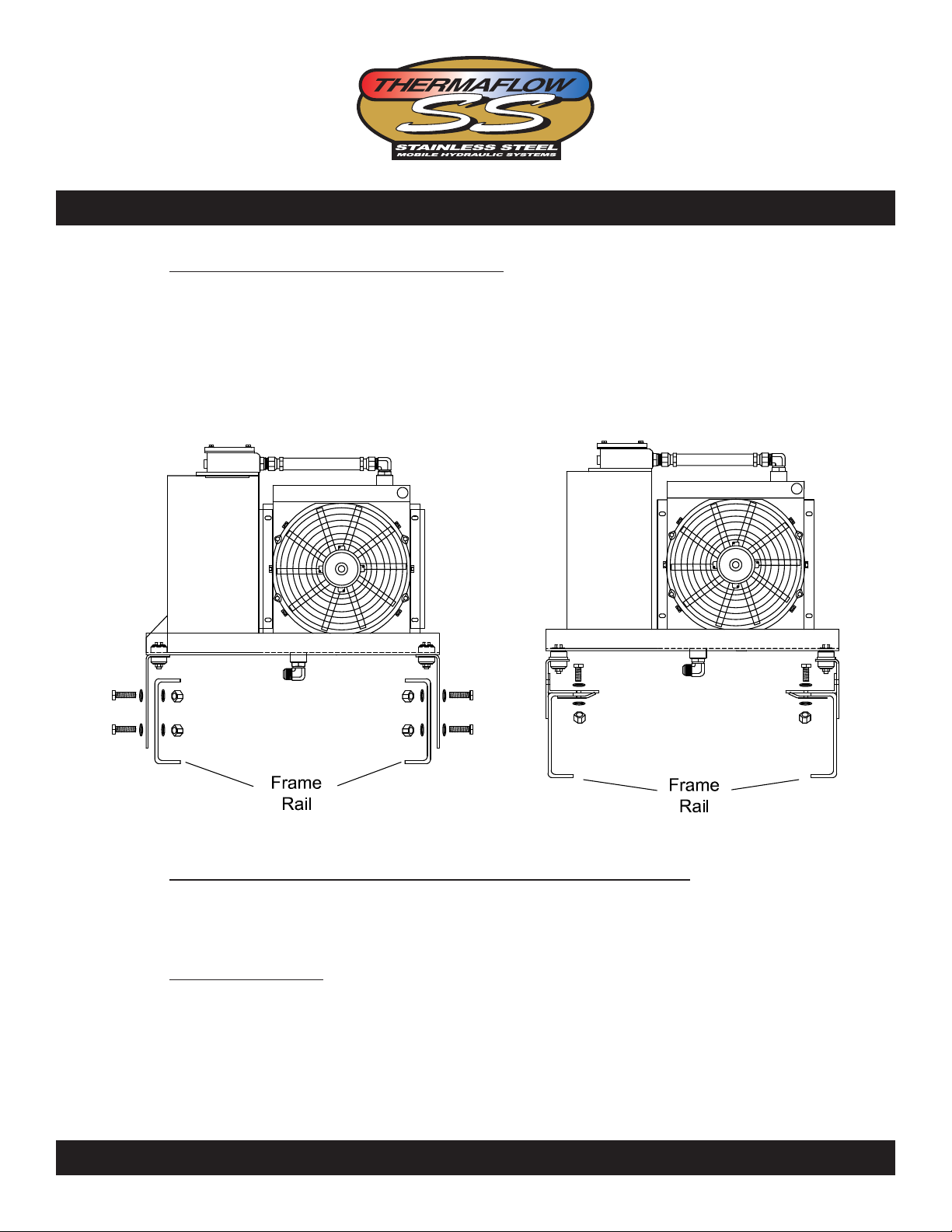
STEP 1 POSITIONING & MOUNTING
The Model SS675 is designed to mount behind the truck cab across the frame rail sides.
A) Diagram A describes two mounting options available. Allow a minimum of 4” on both sides
of the unit for proper airflow.
STEP 2 INSTALLING THE PTO & HYDRAULIC PUMP
A) Install the PTO to the transmission and mount the hydraulic pump according to
the instructions included with the PTO.
HELPFUL HINT: If you are using a direct mount hydraulic pump/PTO combination,
be sure that the pump splines are well lubrication with a heavy grease. This grease
will prevent premature spline wear on the PTO and pump shafts. A small packet of
this grease is available through STAC Inc P/N 300980. Also available from both
MUNCIE and CHELSEA is a new option for a greaseable shaft. This option allows
you to grease these splines without pulling the pump off the PTO.
DIAGRAMA
INSTALLATION GUIDE , OPERATING PROCEDURES & PARTS BREAKDOWN
No Drill Option
PAGE 2
STAC INC l ST PAUL MN l 800-334-7699

STEP 3 ELECTRICAL WIRING (Models with Electric Fan)
Models having a 12 VDC fan motor can be wired two different ways. Listed below are these
options.
OPTION #1 - FAN SWITCH WIRED HOT
This option wires the fan switch so that you can turn the fan on at anytime regardless
of whether the tractor is running or not.
ELECTRICALCONNECTIONS
REDWIRE:Connect to the positive (+) 12VDC battery terminal (20 Amps)
through circuit breaker (150153) provided in electrical kit (150525).
BLACKWIRE:Connect to the truck frame or to the negative (-) battery terminal.
For further illustration follow DIAGRAMB on Page 4.
NOTE:Werecommendthatthepowersupplybetakendirectlyfromabattery
postorsimilarhighcurrentlocation.
OPTION #2 - FAN SWITCH GROUNDED THROUGH AN AIR SWITCH
This option wires the fan switch so that you will only be able to turn the fan on when
the PTO is engaged. This option will allow you to leave the fan switch “ON” so that
you have an automatic operation of the fan when the PTO is engaged. PTO
disengaged fan “OFF”, PTO engaged fan “ON” via an air switch.
ELECTRICALCONNECTIONS
REDWIRE:Connect to the positive (+) 12VDC battery terminal (20 Amps)
through circuit breaker (150153) provided in electrical kit (150525).
BLACKWIRE:Connect to air switch and frame ground.
For further illustration follow DIAGRAMC on Page 5.
NOTE:Werecommendthatthepowersupplybetakendirectlyfromabattery
postorsimilarhighcurrentlocation.
INSTALLATION GUIDE , OPERATING PROCEDURES & PARTS BREAKDOWN
PAGE 3
STAC INC l ST PAUL MN l 800-334-7699

STEP 3 ELECTRICAL WIRING (CONTINUED)
Diagrams B below illustrated proper electrical wiring for electric fan models.
DIAGRAM B
Above electrical schematic illustrates the proper wiring for OPTION#1 from Page 3.
INSTALLATION GUIDE , OPERATING PROCEDURES & PARTS BREAKDOWN
PAGE 4
STAC INC l ST PAUL MN l 800-334-7699

STEP 3 ELECTRICAL WIRING (CONTINUED)
Diagrams C below illustrated proper electrical wiring for electric fan models.
DIAGRAM C
Above electrical schematic illustrates the proper wiring for OPTION#2 from Page 3.
INSTALLATION GUIDE , OPERATING PROCEDURES & PARTS BREAKDOWN
PAGE 5
STAC INC l ST PAUL MN l 800-334-7699

STEP 4 HYDRAULIC PLUMBING
DIAGRAMS D & E show proper plumbing for Models SS675ER, SS675HR, SS675E3000ND
& SS675H3000ND. Please carefully read the Helpful Hints and Notes listed below before
beginning.
HELPFUL HINT: We recommend the use of minimum 1 1/2” suction hose. If the suction
hose is too small the hydraulic pump will cavitate and fail prematurely. A 3/4” pressure
hose is recommended for flows up to 25 gpm. A 1” pressure hose is recommended for
flows greater than 25 gpm. The 675 Series has a 2” suction port for high flow and tandem
applications.
NOTE: Be careful not to over tighten NPT threads. It is very easy to crack these
types of ports when tightening fittings.
DIAGRAM D
INSTALLATION GUIDE , OPERATING PROCEDURES & PARTS BREAKDOWN
PAGE 6
STAC INC l ST PAUL MN l 800-334-7699

DIAGRAM E
STEP 4 HYDRAULIC PLUMBING (Continued)
INSTALLATION GUIDE , OPERATING PROCEDURES & PARTS BREAKDOWN
Optional second relief valve can
be connected to spare port in the
bottom of reservoir.
PAGE 7
STAC INC l ST PAUL MN l 800-334-7699

STEP 5 Final Assembly
A) Complete all hydraulic plumbing.
B) Fill the reservoir until the oil level gets to the top blue line on the site level gage.
C) Set relief valve for system requirements.
NOTE: Aftertheinitialstartupprocedureyouwillneedtoaddoilduetothehydraulic
linesfillinguptocapacity.
NOTE: Over-filling the reservoir will cause the oil to expand up through the breather
assembly when the oil warms up.
NOTE: We recommend using a high grade of hydraulic oil with a Pour Point of -50 F.
This will ensure proper oil flow during extreme cold weather operation. Use of
synthetic hydraulic oils is also recommended. Recommended Oil: MOBIL DTE13 or
equivalent.
STEP 6 START-UP PROCEDURES
The following steps are to ensure that the THERMAFLOW assembly is operating properly.
NOTE: BeforeengagingthePTO,makesurethatallhydrauliclinesareplumbedand
properlytightened.
1) Slowly engage the PTO with engine at idle speed.
NOTE:Watchtheoillevelinthereservoir.Bereadytoaddmoreoilasneededto
maintaintheoillevelbetweenthelevelindicationlinesonthesitelevelgage.
2) Check for hydraulic leaks and repair as needed.
3) Check for fan operation (Electric & Hydraulic).
4) Carefully Tach the product pump speed.
5) Slowly increase the engine speed until desired product pump speed is obtained.
6) Run system for at least five minutes to ensure that system is sufficiently cooling the
hydraulic oil. Using a Hydraulic Flow Meter Kit, set required pressure and flow rates
to system requirements.
7) Slow engine to idle and disengage the PTO.
8) System is ready for operation.
INSTALLATION GUIDE , OPERATING PROCEDURES & PARTS BREAKDOWN
PAGE 8
STAC INC l ST PAUL MN l 800-334-7699

System Maintenance
Hydraulic
Fluid:
l Drain and replace hydraulic oil every 6 to 12 months depending on use.
l Recommended Fluid: Mobil DTE 13 or Equivalent.
Filter:
l Remove 4 cap screws on top of filter housing.
l Remove filter cartridge and spring.
l Replace with new filter cartridge and spring Part Number 675331.
l Apply anti-seize to cap screws and tighten.
Pump:
l Inspect periodically for leaks.
l Check hoses for signs of wear.
Motor:
l Inspect periodically for leaks.
l Check hoses for signs of wear.
PTO
l Grease output shaft every 6 to 12 months depending on use.
l If PTO does not have a grease zerk on output shaft, remove direct mount
hydraulic pump and grease the output shaft using a high quality gear lube.
INSTALLATION GUIDE , OPERATING PROCEDURES & PARTS BREAKDOWN
PAGE 9
STAC INC l ST PAUL MN l 800-334-7699

Troubleshooting
SafetyFirst!
Think about it before you do it. Our systems use controlled fluid pressure and converts it to rotational movement. This
means that the system pressure operates around 2000 psi. A pin hole leak of fluid at this pressure can be dangerous.
Use caution when loosening fittings, system pressure can be maintained for a period of time after shutdown.
Troubleshooting
Always inspect the things easiest to eliminate first. Look for faulty linkage or wiring that controls the PTO,pump or
motor. Look at the fluid level and appearance of the oil. Check temperatures and pressures.
ExcessiveHeat:
l Clean air passages through heat exchanger.
l Check fan operation.
l Check setting of relief valve.
l Check temperature of suction line vs outlet line temperature. If the outlet temperature is noticeably hotter, the pump
is cavitating.
l Check for contamination in relief valve. Clean and replace.
l Check for added flow controls. If a flow control has been added to the system, excess heat can be generated by the
added restriction to flow.
LossofMotorSpeed:
l Check oil level.
l Ensure recommended engine idle speed is maintained.
l Check output pressure of the pump. If system pressure cannot be maintained, attempt to adjust the relief valve
setting to max system pressure. If this does not make a noticeable change, make sure to return relief setting to
original position and bring the pump and motor to a hydraulic specialist for bench testing and possible replacement.
ExcessiveNoise:
l Check oil level. Fill to proper level.
l Ensure use of recommended oil type and weight.
l Ensure suction line to pump is at least 1 1/2”.
l Ensure there is no restriction in suction line.
OilDiscoloration:
l Ensure suction line connections are tight.
l Ensure oil is free from water and contaminants. Drain and refill with recommended oil and replace filter.
l Ensure use of recommended oil type and weight.
INSTALLATION GUIDE , OPERATING PROCEDURES & PARTS BREAKDOWN
PAGE 10
STAC INC l ST PAUL MN l 800-334-7699

Specifications
Max Flow Rate: 50 gpm
Max Pressure: 5000 psi with
optional high pressure relief valve
Reservoir: 7.2 gal
Weight: 100 lbs
Suction Line: 1.5-2 Inch
Pressure Lines: 1 Inch
Warranty: 2 years
Oil - The recommended oil is Mobil
DTE 13 or equivalent. Mobil DTE
13 is a supreme performance anti-
wear hydraulic oil engineered for wide
temperature range applications. It
exhibits optimum flow characteristics at
sub-zero temperatures and is resistant
to shearing and viscosity loss so that
system efficiency is maintained and
internal pump leakage is minimized
at high operating temperatures and
pressures.
INSTALLATION GUIDE , OPERATING PROCEDURES & PARTS BREAKDOWN
PAGE 11
STAC INC l ST PAUL MN l 800-334-7699

MODEL SS675ER / SS675E3000ND
INSTALLATION GUIDE , OPERATING PROCEDURES & PARTS BREAKDOWN
PAGE 12
STAC INC l ST PAUL MN l 800-334-7699

INSTALLATION GUIDE , OPERATING PROCEDURES & PARTS BREAKDOWN
MODEL SS675HR / SS675H3000ND
PAGE 13
STAC INC l ST PAUL MN l 800-334-7699

Parts List
Item# Part# Description
1 675330 Filter Assembly
2 675020 Heat Ex. Housing
3 675050 Screen
4 675728 Tube
5 300416 Elbow
6 675300 Heat Exchanger
7 675060 Fan Bracket (2)
8 300306 Fan, Electric
9 675071 Leg, Drill Type (2)
10 300200 Sock Mount (4)
11 300032 Spacer (4)
12 375418 Fitting, Return
13 150714 Fitting, Relief Valve
14 300416 Elbow, Relief Valve (2)
15 675702 Relief Valve, 50 gpm
16 675030 Bottom Tray
17 675010 Tank
18 300334 Site Glass
19 600332 Breather Assembly
20 675331 Replacement Filter
21 375418 Fitting, Filter
22 675070 Leg, No Drill Option
23 675074 Lower Frame Clamp
24 675072 Upper Frame Clamp
25 300702 30 gpm Relief Valve
26 300708 Elbow
27 300748 Fitting
28 2406-12-8 Reducer
29 675515 Switch Harness
30 934850 Fan Guard
31 600820 Hyd Fan Blade
32 675892 Hyd Fan Motor Return Hose
33a 600732 Fitting, SS675HR Model
33b 150912 Fitting, SS675H3000ND Model
34 150510 Hyd Fan Motor
35 150908 Fitting
36 600830 Flow Control
37 675890 Hyd Fan Motor Pressure Hose
38 2501-6-8 Fitting
39 2406-16-8 Reducer
40 675734 Tee
41 600734 Tee
42 675850 Hydraulic Fan Shroud
INSTALLATION GUIDE , OPERATING PROCEDURES & PARTS BREAKDOWN
PAGE 14
STAC INC l ST PAUL MN l 800-334-7699

Product Offering
Fans
Spal
Crowley
Fittings
Tompkins
Weatherhead
Faster
HeatExchangers
AKG Thermal Systems
Thermal Transfer
Flat Plate
HydraulicMotors
Barnes
Eaton/Charlynn
Muncie
Permco
Rexroth
PTO’s
Muncie
Pumps
Muncie
Parker
Permco
Rexroth
INSTALLATION GUIDE , OPERATING PROCEDURES & PARTS BREAKDOWN
PAGE 15
STAC INC l ST PAUL MN l 800-334-7699


The THERMAFLOW SS675 Series Hydraulic Cooler is warranted against any
defect in material and workmanship which existed at the time of sale by STAC Inc.
according to the following provisions, subject to the requirements that the Cooler
must be used only in accordance with the catalogue and package instructions.
The Cooler is warranted for a period of TWO Years from the date of installation. If
during the warranty period the cooler fails to operate to STAC’s specifications due
to a defect in any part in material or workmanship that existed at the time of sale by
STAC Inc., the defective part will be repaired or replaced, at STAC Inc.’s discretion,
at no charge, if the defective part is returned to STAC Inc. with transportation
prepaid.
The above warranty shall terminate if any alterations or repairs are made to the
System other than at an authorized dealer or if the cooler is used on any equipment
other than the equipment upon which it is first installed.
THE FORGOING WARRANTIES ARE IN LIEU OF ALL OTHER OBLIGATIONS
AND LIABILITIES, INCLUDING NEGLIGENCE AND ALL WARRANTIES OF
MERCHANTABILITY AND SUITABILITY, EXPRESSED OR IMPLIED AND STATE
STAC INC.’S ENTIRE AND EXCLUSIVE LIABILITY AND BUYER’S EXCLUSIVE
REMEDY FOR ANY CLAIM OF DAMAGES IN CONNECTION WITH THE SALE,
REPAIR OR REPLACEMENT OF THE ABOVE GOODS, THEIR DESIGN,
INSTALLATION OR OPERATION. STAC INC. WILL IN NO EVENT BE LIABLE
FOR ANY DIRECT, INDIRECT, SPECIAL, INCIDENTAL OR CONSEQUENTIAL
DAMAGES WHATSOEVER, AND OUR LIABILITY UNDER NO CIRCUMSTANCES
WILL EXCEED THE CONTRACT PRICE FOR THE GOODS FOR WHICH
LIABILITY IS CLAIMED.
60 West Sycamore Street • St. Paul, MN 55117
800-334-7699 • 763-235-7822 Fax
Web: www.thermaflow.com
Inc.
THERMAFLOW WARRANTY
Thermaflow is a registered trademark of STAC, Inc. All Rights Reserved. Form 675901 Rev: 02/12
This manual suits for next models
4
Table of contents
Popular Accessories manuals by other brands

Altinex
Altinex Tilt `N Plug Interconnect Box TNP100UK user guide

Pyle
Pyle PPBCM28 instruction manual

Keysight Technologies
Keysight Technologies N6841A installation guide

YAK-POWER
YAK-POWER YPLEDK-B4 installation instructions

Austro Engine
Austro Engine E4 Series installation manual

Cygnett
Cygnett CY3481PBCHE user manual