Thermal Instrument Co. 9500P User manual

Thermal Instrument Company (215) 355-8400 info@thermalinstrument.com 1
Rev: 9/2019
CUSTOMER NAME:
CUSTOMER PO#:
SERIAL NUMBER:
MODEL DESCRIPTION:
APPLICATION SERVICE:
LINE SIZE:
POWER:
OUTPUT: 4-20 MADC
Congratulations and thank you for your purchase of a Thermal Instrument Company mass flow meter system.
CUSTOMER ORDER DETAILS
217 Sterner Mill Road
Trevose, PA 19053 U.S.A.
P: 215-355-8400
F: 215-355-1789
Info@ThermalInstrument.com
www.ThermalInstrument.com
OPERATIONS & INSTALLATION MANUAL

Thermal Instrument Company (215) 355-8400 info@thermalinstrument.com 2
Rev: 9/2019
MODEL 9500P FLOW TRANSMITTER
WITH INSERTION OR IN-LINE
STYLE FLOW TRANSDUCER
Flow Meter Selection ..………………………………………………………………….. 3
Field Wiring Diagram ..…………………………………………………………………… 4
Outline Dimensions ..…………………………………………………………………….. 5
Flow Curves & Calibration ..…………………………………………………………… 6
Spec Sheet—Meter Configuration Page Introduction ..……………………… 7
Guidelines & Precautions ..……………………………………………………………. 8
Installation ..………………………………………………………………………………… 10
Insertion Probe Install Guide ..……………………………………………………….. 14 - 15
Operation & Info ..…………………………………………………………………………. 16
Totalizer Reset ..…………………………………………………………………………... 18
Block Diagram/Power Board ..………………………………………………………… 19
General Precautions ..……………………………………………………………………. 20
Instrument Housing ..…………………………………………………………………….. 28
Field Calibration ..…………………………………………………………………………. 33
Troubleshooting ..…………………………………………………………………………. 34-36
Spare Parts ..………………………………………………………………………………… 37
PAGE
Thermal Instrument Company (215) 355-8400 info@thermalinstrument.com 3
Rev: 9/2019
HART Communication - 24 VDC Internal Power
- 24 VDC External Power
Integral
24 VDC 110/120
24VDC Battery Powered
220 VAC
1A.2 Flow Meter Selection
4-20 mADC Temperature
4-20 mADC Flow Rate
None Flow Rate & Totalizer
Flow Rate
Remote
OUTPUT SIGNAL(S):
INPUT POWER:
DISPLAY TYPE:
TRANSMITTER / ELECTRONICS LOCATION:
Solar Powered
Modbus RS 485 (Included Flash Drive & Connection Cable)
Other:
Other:
Model #:
Pulse Output
Pulse Setup:_____________________________________________________
Thermal Instrument Company (215) 355-8400 info@thermalinstrument.com 4
Rev: 9/2019
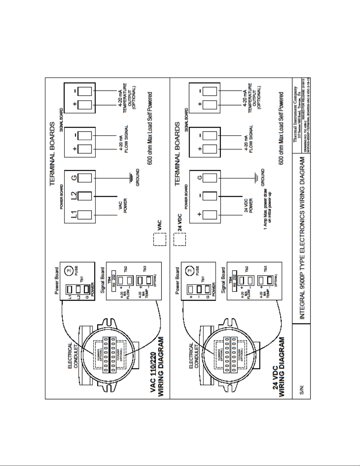
1A.3 Wiring Diagrams

Thermal Instrument Company (215) 355-8400 info@thermalinstrument.com 5
Rev: 9/2019
Specific Outline Dimensions

Thermal Instrument Company (215) 355-8400 info@thermalinstrument.com 6
Rev: 9/2019
All Flow Curves & Calibration Spec Sheet

Thermal Instrument Company (215) 355-8400 info@thermalinstrument.com 7
Rev: 9/2019
Introduction
1.1 Preface
These instructions contain all of the information that you will require for using this flow meter
from Thermal Instrument Company.
These instructions are aimed at people mechanically installing the flow meter, connecting it
electrically, configuring the parameters and commissioning it as well as service and
maintenance engineers.
Note
It is the responsibility of the customer that the instructions and directions provided in the
manual are read, understood and followed by the relevant personnel before installing this
device.
1.2 Flow Meter Configuration
Items Inspection
1. Check for mechanical damage due to possible improper handling during shipment. All
claims for damage are to be made promptly with the shipping company.
2. Make sure that the information on the product identifier plate and labels (Figure 1 above)
corresponds to the ordering information.
1.3 Further Information
The contents of these operating instructions shall not become part of or modify any prior or
existing agreement such as the original quotation, or any other written communications.
These operating instructions are a guidance for this flow meter and do not create new
warranties or modify the existing warranty.
Product Information available on our website:
(http://www.thermalinstrument.com)
1.0
The Flow Meter Applicaon Details can be con-
rmed on Page #3 of this manual or by reviewing
the label and tags aached to each specic ow
meter as shown in Figure 1.
Each ow meter has a specic Serial # for iden-
caon purposes. Note: When Receiving Remote
Electronic Transmiers, the ow element and
transmier are a matched set.
Figure 1—Example Only

Thermal Instrument Company (215) 355-8400 info@thermalinstrument.com 8
Rev: 9/2019
Receiving / Inspection
- Unpack carefully and inspect overall condition
- Check the packing list to compare what you received is all there
If the above items are fine, then move on to the next section, otherwise contact our customer
support group at (215) 355-8400 and provide us with purchase order number or serial number
of the flow meter.
Factory Calibration Note
This flow meter from Thermal Instrument Company has been factory calibrated to the
specifications and flow range as stipulated by the customer. There is no need to perform
any verification or calibration on this device prior to mounting and start-up in the application.
Prior to Installation
Qualified electrical personnel should be installing this instrument. The installation should be
done per National Electrical Code and the power to the electrical wiring should be off during the
installation. Where the instructions call out for use of electrical current, the operator assumes
all responsibilities for conformance to safety and practices.
Alerts
This flow meter is not designed for weld-in place applications with the exception of the
UHP (Ultra High Pure) in-line flow designs. The conventional welding technique can cause
damage to the Nickel or Platinum sensors from the current being passed from ground to the
hot weld side.
Damage due to moisture ingress into the enclosure is not covered under the warranty of this
product and proper conduit seals must be applied for all-weather conditions. This flow
transmitter contains electrostatic discharge (ESD) sensitive components, so use proper ESD
precautions when handling the device.
Verify Mounting Area for Insertion or In-Line Flow design to make certain that everything fits
properly.
Installation Point
Make sure that there are 10 pipe diameters upstream and 5 pipe diameters down stream of the
flow meter from any bends or interferences in the process piping or ductwork in order to achieve
the greatest accuracy.
2.0 General Guidelines & Precautions

Thermal Instrument Company (215) 355-8400 info@thermalinstrument.com 9
Rev: 9/2019
2.0 General Guidelines (Continued)
Mechanical Care of Enclosure
Be careful of the enclosed electronics when removing the condulet cover. After the initial
installation, never open the condulet when the power is connected, especially in a classified
hazardous area. Gently lift the cover from the 9500P electronic assembly and place it in a safe
location where dirt cannot get inside or, if the display option has been selected, where dirt can
get on the inside of the viewing window. When replacing the cover, take special care that the
display legend plate is centered on the display and that the cover window lugs do not hit the
legend plate in the last two or three turns of the cover.
Electrical Care of Enclosure
Proper wire size or gauge selected for all connections should be the minimum allowable by
your plant standards and regulations. The enclosure has limited space available for large
gauge wire and we recommend no larger than 12 gauge for power. When snaking the wires around
the electronic assembly, special care should be taken of any protruding parts. The parts are capable
of withstanding some abuse, but still be cautious not to force the wire through.
Thermal Instrument Company (215) 355-8400 info@thermalinstrument.com 10
Rev: 9/2019
2.1 Installation / Mounting of Flow Meter
Verify the Dimensions of the Flow Meter against your process connection and piping.
The Thermal Instrument Company Model 62-9 insertion probe has a variety of process mounting
connections, from MNPT to welded flange, The insertion probe commonly comes with an adjustable
mechanical connection which can be tightened down for permanent mounting. Verify all mounting
and installation variables before tightening process packing gland.
If the installation is for Thermal Instrument Company Model 600-9 in-line flow tube design, then make
certain that the pipe diameters and mounting sections are verified.
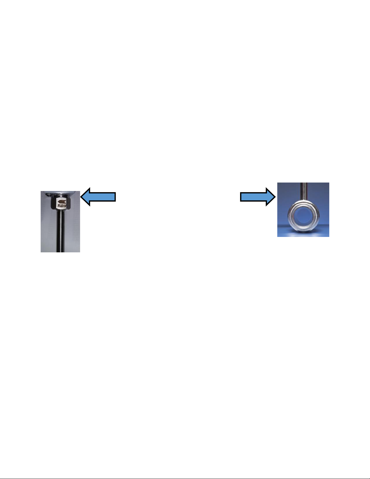
Verify the Flow Direction for the Flow Meter and Proper Placement
The 62-9 insertion probe has an indexing arrow on the flat portion of the process connection located
just below the base of the enclosure. On Model 600-9 it will be on flow element body. See Figure Be-
low.
Align the insertion probe during the installation so that the flat areas of the mechanical process
connection with the arrow are parallel to the direction of the process flow, and the arrow points
in the direction of the process flow.
For the 600-9 in-line flow tube assembly, the indexing arrow is etched on the flow tube, and
should be pointing in the direction of the flow. If the flow device is not mounted in the proper
direction, then there will be a reduction in accuracy.
Compression Fitting Mounting (62-9 Insertion Probe Style)
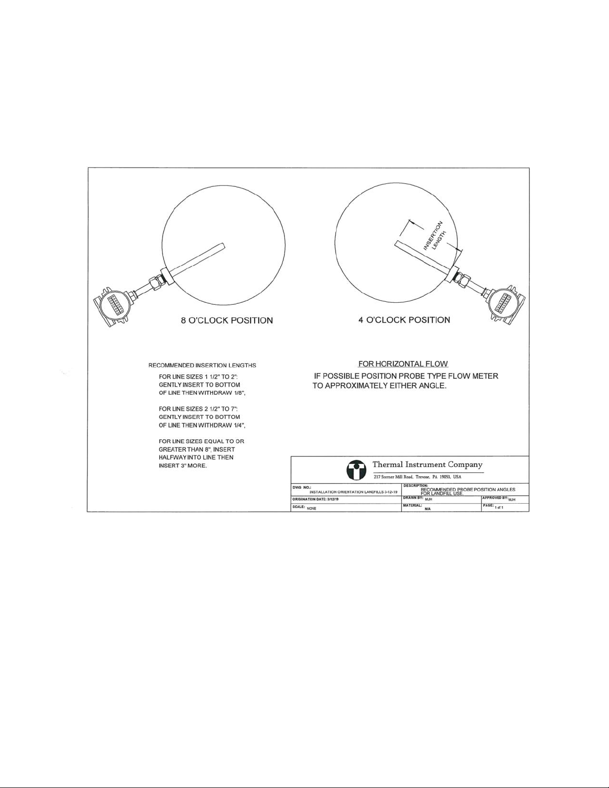
A. Determine the inside diameter of the process pipe at the pre-determined mounting location. If the
Inner pipe diameter is 1-1/2” to 2”, then the insertion probe will utilize the dual tip design and would
be inserted to the bottom of the line and withdrawn up by 1/8”. For line sizes 2-1/2” to 7”, the probe
would be inserted completely to the bottom of the line, and then withdrawn 1/4”. For line sizes equal to
or greater than 8”, insert the probe halfway into the line, and then insert 3” further for optimal position-
ing.
B. Once inserted into the line at the proper positioning, tighten down the connection to ANSI B16.5
torque specifications. Make sure that proper thread sealants are applied prior to torque down of the
fitting.
Figure Left: Index Arrow
on 62-9 Insertion Probe
Figure Right: 600-9
In-Line Flow Tube
(actual tube will have flow
direction arrow)

Thermal Instrument Company (215) 355-8400 info@thermalinstrument.com 11
Rev: 9/2019
Compression fitting Mounting Continued
C. Adjust the probe so that the flats of the mechanical process gland are parallel with the flow and
that the indexing arrow is also in the direction of the flow path.
D. Once the insertion length and probe positioning are correct, tighten the mechanical gland
assembly using two wrenches with one on the smaller connection and the other on the larger
connection. Do not over tighten by more than one and one half turn. The mechanical packing
gland assembly can be readjusted if needed.
NPT Pipe Thread Mounting (62-9 Insertion Probe Only)
A. Make certain that a proper environmental sealant is applied to the process threads of the
insertion probe prior to installation and tightening into line.
B. Make certain that the condulet is not rotated more than 180º with the insertion probe
fastened to the process line as the RTD (Resistance Temperature Detector) wires could be damaged.
C. The threads on the insertion probe are right handed and should not be over tightened or
cross threaded as this can cause moisture to leak out or ingress.
Flanged Mounting (62-9 Insertion Probe Only)
A. Make certain that the proper sized flow meter flange and ANSI rating is correct for the mating
process side of the flange. Verify the line pressure vs. the overall flange rating.
B. Make certain that a new gasket is available for the flange connection and that the area on
the process flange side is cleaned and free of any raised areas that could be a leakage path
for media inside the line.
C. Prior to fastening the flanges together, make sure that the indexing arrow is parallel with
the flow direction.
D. Carefully mount the flow meter with the flange to the process side flange and use the bolts
with nuts to secure the flanges together.
2.1 Installation/Mounting Continued
Thermal Instrument Company (215) 355-8400 info@thermalinstrument.com 12
Rev: 9/2019
2.2 9500P Integral Electronics Design
The Model 9500P transmitter / electronics is available as an integral design. The integral design
features the transmitter / electronics mounted atop the insertion or in-line flow style sensors.
2.3 9500P Remote Electronics Design
The Model 9500P transmitter / electronics is also available as a remote mounted design whereby
the transmitter / electronics can be remotely located up to 2000 feet from the sensing element via
interconnecting cable. This remote mount version then comprises the 9500P transmitter /
electronics in the remote area and a junction box enclosure with a wiring terminal block mounted
atop the sensing element or probe design.
2.4 Insertion Style Probes Model 62-9
For installation of the 62-9 insertion probe, the 10 upstream and 5 down stream conditions
still apply. The insertion probe must be rotated so that the index arrow etched on the probe is
facing towards the flow of the media.
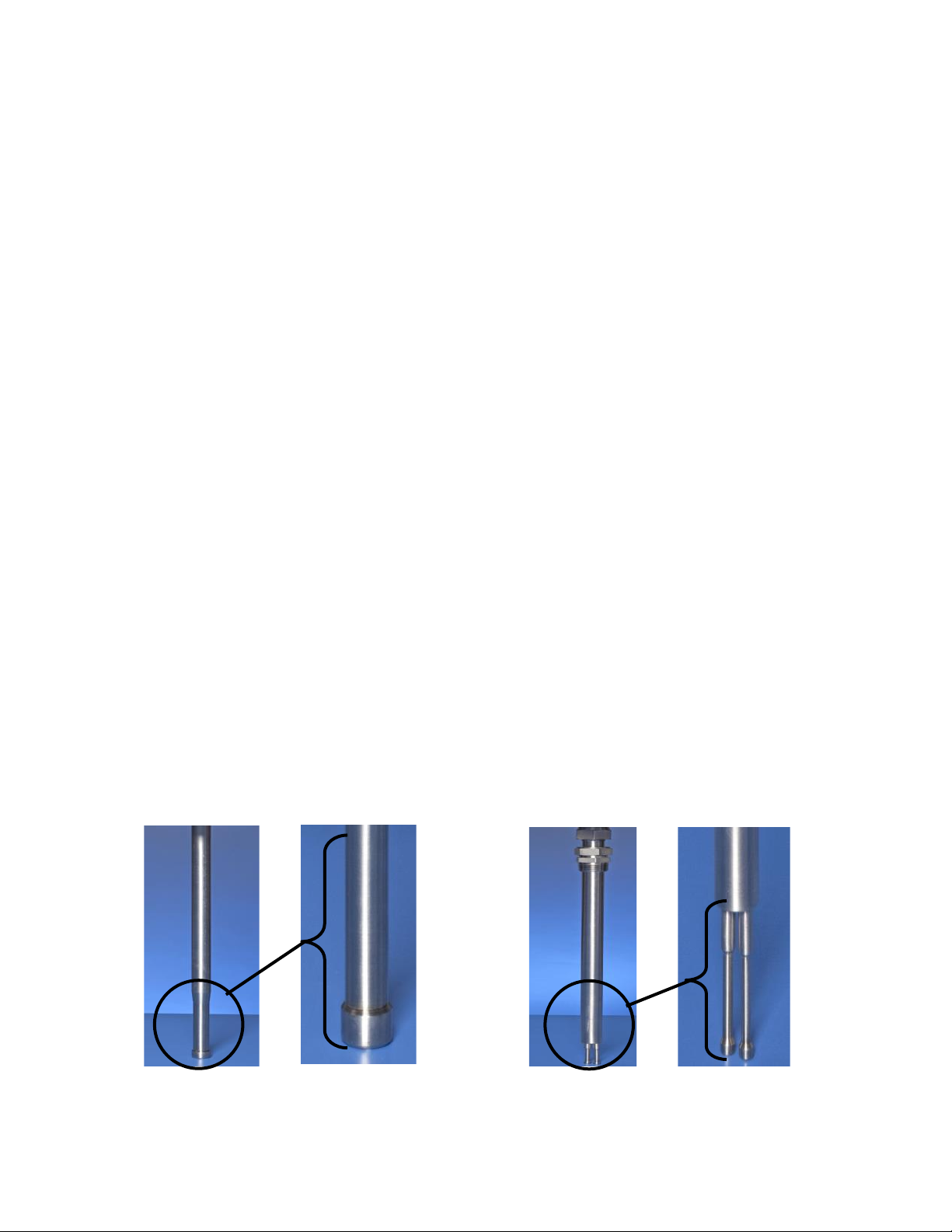
Thermal Instrument Company has two styles for the insertion probes; one is the dual tip which is
most often applied for lines smaller than 2” and the second design is the single piece machined
probe, which is available in 1/2”, 3/4” or 1” OD size or greater. The size of the probe is deter-
mined by the flow velocity of the media as well as the application parameters like operating
pressure. In Figure X & Y below, we show the insertion probes for the single piece machined
probe and the dual tip design.
Installation/Mounting Continued
Model 62-9 Single Piece
Machined Insertion Probe Model 62-9DT Dual
Tip Insertion Probe
FIGURE X FIGURE Y

Thermal Instrument Company (215) 355-8400 info@thermalinstrument.com 13
Rev: 9/2019
2.5 Proper Sealing of the Transmitter / Electronics
Prior to mounting the insertion style probe into the tube or pipe line, make certain that there is a
proper seal applied to the process connection. If the process connection is an NPT style, then
Teflon tape or a liquid style sealant is applied. If the connection on the probe is a flange or other
type of surface connection, then an appropriate gasket material should be in place between the
probe connection and the pipe mounting section.
Additionally, the conduit seals on the transmitter / electronics enclosure should also be done
properly so that no external moisture can penetrate the threaded area. Also, be certain to
tighten down the enclosure cover for the integral / compact transmitter and / or remote junction
enclosure and remote mounted transmitter / electronics. Thermal Instrument Company is not
responsible for any 9500P transmitter, junction enclosure, or external equipment damage due
to negligence on improper sealing of any conduits going to the enclosures or the enclosure
covers not being secured with the O-ring gasket on the base of the transmitter / electronics.

Thermal Instrument Company (215) 355-8400 info@thermalinstrument.com 14
Rev: 9/2019
Recommended Insertion Probe Installation
Thermal Instrument Company (215) 355-8400 info@thermalinstrument.com 15
Rev: 9/2019
Recommended Insertion Probe Installation (cont.)
Recommended installation when customer process is known to have significant moisture in
the pipe. Significant moisture is characterized by the presence of water droplets contacting
the flow sensor.

Thermal Instrument Company (215) 355-8400 info@thermalinstrument.com 16
Rev: 9/2019
3.0 Transmitter Information & Wiring
3.1 Operation
Flow Transducer
In this section, there will be references to functional block diagrams. See Figure 2 for the main
block diagram on page 17. The Thermal Instrument Company thermal mass flow meter utilizes a
unique compound bridge circuit that measures and controls the temperature of the precision RTD
that is bonded to the dry side of the media conduit.
The power required to maintain this temperature is proportional to the mass flow rate of the fluid
or gas. This raw measured signal then goes through a linearization circuit to straighten the flow
curve. Additionally, some method of temperature compensation must be performed on the signal.
Electronics Transmitter
The transmitter / electronics used with the majority of the flow transducers is the 9500P. This
electronics has a series of printed circuit boards with interconnectivity. The mass flow measurement
and functionality of the design is accomplished on the Bridge Voltage Control Board shown in
Figure 3 on page 17. The output signal is passed to the Logic Control Board where the non-linear
signal is digitized. This digital value is used to look up the corresponding flow value in an EEPROM
(Electrically Erasable Programmable Read-Only Memory). The linearized value is then used to drive
an LED flow rate display, an 8-digit totalizer, and the analog 4 to 20 mADC current flow signal.
The Logic Control Board incorporates a micro-processor, which controls the data flow and modifies
the calculations according to parameters stored in EEPROM. The microprocessor also controls the
communications link between the flow meter and a personal computer. This communication link is
used to monitor and change the operating factors for the flow device.
3.2 Input Power and Output Signals
110/220 VAC - The electronics may be powered by either 110 VAC or 220 VAC, but the selection
is made by jumpers not accessible in the field. As shown on the Field Wiring Drawing No. TIC-436-
2, the HI line is connected to Terminal Block 1, point 1 at the top. The LO (neutral) line is connect-
ed to point 2 and the earth line is connected to point 3. Take special note that the two-point termi-
nal blocks are for the output signals. DO NOT CONNECT HIGH VOLTAGE POWER TO THESE
BLOCKS. There are protective Poly Switch breakers on the output signal lines and they will
“open” up if overloaded but circuits can still be damaged.

Thermal Instrument Company (215) 355-8400 info@thermalinstrument.com 17
Rev: 9/2019
3.0 Transmitter Information & Wiring
3.2 Input Power and Output Signals
24 VDC - (22 volts DC min, 30 volts DC max) - As shown on the Field Wiring Drawing No. TIC-436-2, (Page 4) the
positive line is connected to Terminal Block 1, point 1 at the top. The negative line is connected to point 2 and the earth
line (when used) is connected to point 3. Take special note that the two-point terminal blocks are for the output signals.
DO NOT CONNECT HIGH VOLTAGE POWER TO THESE BLOCKS. There are protective Poly Switch breakers on the
output signal lines and they will “open” up if overloaded, but circuits can still be damaged.
The 24 volt version of the Model 9500 can be connected in a three-wire configuration (four - wire with temperature output).
In this configuration the current signal common to the flowmeter is eliminated and the common line for the output signal is
connected at the 24 volt source negative. If plant regulations permit, the three-wire configuration could be two wires plus
shield for the common.
Output Signals
Terminals are provided for local instrument powered two-wire signals (positive and common). If the Temperature Trans-
miter option has been provided, a single wire common connection may be used or two-wire cables may be run. There are
protective Poly Switch breakers on the output signal lines and they will “open” up if overloaded but circuits can still be
damaged. When power is on if there is zero output current (there should be at least 4 mA even through a current meter)
disconnect the field wiring and check the terminal block points for a voltage. Presence of a voltage (typically 20 to 30 volts)
with no current flow indicates that the Poly Switch breakers have been tripped. Power must be turned off if the Poly Switch
breakers are tripped in order for them to reset. They do not need to be replaced as a fuse. Maximum load resistance is
500 ohms.
Flow - The 4-20 mA flow signal is at Terminal Block 2, the positive connection on point 1 (at the top of Block 2) and the
negative on point 2. The output current signal is a 4 mADC at zero flow and 20 mADC at 100% of rated flow.
Temperature (optional) - The 4-20 mA temperature signal is at Terminal Block 3, the positive connection on point
1 (at the top of Block 3) and the negative on point 2.
Totalizer Pulse Output - The 9500 pulse output’s standard configuration is 12 Volt DC pulse with a 20 millisecond on
time and 1 pulse per specified flow range. The three variables are, 1 - Voltage pulse or dry contact closures output, 2 –
Length of pulse 20 millisecond standard can be shorter or longer. (Example: 5 millisecond, 100 millisecond, 1 second, Etc.)
3 - Pulses per unit of Flow rate, example: 1 pulse per flow unit, 10 pulses per flow unit. The three variables are not field
changeable therefore Thermal Instrument needs to know what are the variables need to accommodate the equipment inter-
face.
Start-up Operation - With all connections having been completed and tested, a short but fast flow rate should be ob-
tained in order to clean gas bubbles and impurities from the flow tube.
CAUTION - Flow and transducer must be within 50º C (122°F) of operating temperature before power is applied. Sensors
may be damaged if transducer temperature is below this limit and/or calibration may not be accurate.
Apply power and allow a 10 minute warm-up period.

Thermal Instrument Company (215) 355-8400 info@thermalinstrument.com 18
Rev: 9/2019
3.0 Transmitter Information & Wiring
3.3 Continued Operation
Electronics Unit Field Service Details
Terminal Board
Figure 2 (Pg.17) shows the block diagram. Figure 3 (Pg.17) shows the component configuration for
the two field wiring boards. All field wiring is made to the terminal board. There are two (optionally
three) terminalblocks. Connect the input power to the three-position block TB1 according to TIC-436-
2 on the field wiring diagram. Terminal Block TB2 carries the 4-20 mADC flow signal and, if optional-
ly ordered, TB3 carries the 4-20 mADC signal for the specified temperature range. Both current sig-
nal require a loop with a maximum resistance of 500 ohms. The signals are powered by the internal
electronics and must not be connected to an external power supply. (NOTE: Hart & Modbus options
require external power)
Flow Bridge Voltage Control Board
The flow bridge voltage control board controls the flow transducer sensor and provides the
non-linear flow signal to the logic board.
In calibration, the potentiometer R2 is set to balance the temperature sensor with the flow sensor
at the lowest temperature in the application range. A second pot, R11 is set to balance the bridge
at the high extreme of the application temperature range. These two adjustments are determined
in calibration and should NOT be changed.
Logic Board
The logic board converts the non-linear analog flow signal to a digital value, determines the linear
equivalent from the data stored in an Electronically Erasable Programmable Read Only Memory
(EEPROM), runs an 8-Digit totalizer and outputs the linear flow data as an analog signal (4 to 20
mADC) and a 5-1/2 digit flow rate display.
R6 is adjusted so that the voltage on TB5 pin 1 is equal to the zero flow voltage from the flow bridge.
Adjustment is then made to R7 so, when the maximum voltage is applied to the S+ input,the voltage
at TB5 pin 3 equals 4.096 volts. Potentiometer R17 provides the 4 mA adjustment for the output cur
rent signal.
Access to Menu System & Resetting Totalizer is done on the Logic Board
To Reset Totalizer Display to “0”. Press and hold the black push button (See Figure 3 on Page
19) labeled (SW4) in for 5 seconds until display flashes. Totalizer has been reset at this point.
See Addendum on Page 35 for additional information on the Integral Menu System.
To Reset Totalizer Display
to “0”. Press and hold the
black push button (See
Figure 3 on Page 19)
labeled (SW4) in for 5
seconds until display
flashes. Totalizer has been
reset at this point.

Thermal Instrument Company (215) 355-8400 info@thermalinstrument.com 19
Rev: 9/2019
Figures for Electrical Diagrams from Previous Page
Figure 2 - Block Diagram
Figure 3 - Two Field Wiring Boards

Thermal Instrument Company (215) 355-8400 info@thermalinstrument.com 20
Rev: 9/2019
General Precautions
Table of contents
Popular Measuring Instrument manuals by other brands

Omicron Lab
Omicron Lab Bode 100 Detailed Functional & Calibration Check

Stabila
Stabila Laser Distancer LD 320 operating instructions

Apera Instruments
Apera Instruments DO8500 instruction manual

OptoTest
OptoTest OP250 Short instructions

GRAUPNER
GRAUPNER 1955 user manual

Agilent Technologies
Agilent Technologies ESA-E Series user guide


