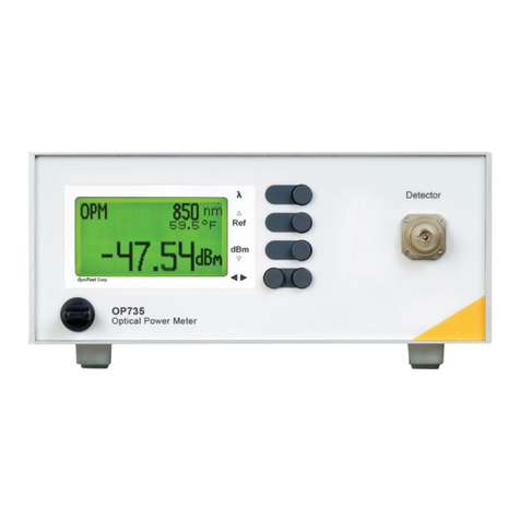
OP250
Stabilized Light Source
850nm VCSEL
62.5/125µm
Power ON | O Button
Push button to power the module,
a green standby indicator(s) will
light up. This will put the module
into standby mode, the sources are
not active. Push the button to turn
power o.
NOTE:Connecting to the USB
port will power on the module into
standby mode. If the unit is powered
o and data is sent via USB the
module will power on as well.
Increase/Decrease Optical Power
Pushing the up or down button will
increase or decrease the optical
power of the selected source(s). If
the button is pressed continuously
the rate of increase will speed up
and eventually stop at the minimum
respectively maximum of the setting.
NOTE: The range of the power
adjustment is different for each laser
and to be used for minimal fine
tuning of source power. For loss
measurements a proper REFERENCE
is necessary all the time.
Source Mode
Single Source Module:
The source mode button
activates or deactivates the
source. If activated the yellow
indicator lights up.
Dual Source Module:
The source mode button
sequentially activates or de-
activates the two sources in
the following order: source 1,
source 2, both sources, all o.
The corresponding yellow
indicators will light up.
Source Description
The wavelength and nominal source power
are noted in the corresponding elds.
Optical Port
Depending on the option the OP250 is equipped
with one or two optical ports. If not in use the
optical port should be kept clean from dust and
covered with the appropriate cap.
USB Port
Use USB A-B cable to connect
to the computer port. The USB
port provides power to the
module, charges the battery and
provides the high speed data
interface to the computer.
LED Indicator for external DC voltage.
Lights up if external voltage is present.
LED Indicator for USB port voltage.
Lights up if USB port is active, powers
the module and charges battery.
Connector for external DC power supply
Voltage range: +5VDC nominal, 0.5A
Note: Charging a fully discharged battery
through this port requires 0.5A current.
Over voltage on this port will overheat the
internal charging circuit.
LED Indicators
Green LED: Indicates standby power of
corresponding source. During USB trac
the upper green LED will ash briey.
Yellow LED: Indicates the corresponding
source is active. During adjustment of the
source power the corresponding LED will
ash briey.
negative contact positive contact
OP250
OP250
Source Specific Parameters
Source Wavelength
The nominal wavelength for each source is indicated by
the module part number (for example OP250-LD-850
would utilize an 850nm LED source).
The actual center wavelength for each source can vary
within ±20nm.
Output Power
The nominal output power for each source is a minimal
specification. With the source level adjustment set
to maximum this nominal output power should be
achieved*.
*A clean connector and matching fiber type is necessary to
achieve this.
Power Stability
Inherently the OP250sources are stable to better than
±0.05dB*. For true single mode sources this stability
can be easily achieved by using all singlemode fiber.
For stability measurements using multimode fiber the
results can expand beyond this range due to changes
in modal distribution (caused by fiber movement and
temperature).
*Over 12 hours with a max. change of 1ºC
Laser Classifications
All OP250 source units with internal laser sources utilize a
Class I LASER Source.
OptoTest strongly suggests that all necessary
precautions be taken whenever any Class I or Class
III LASER source is used.


