Thermalright TRUE Spirit 140 Power User manual
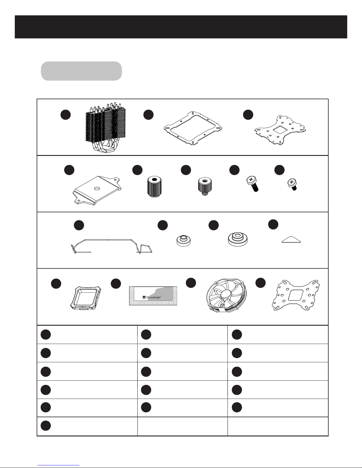
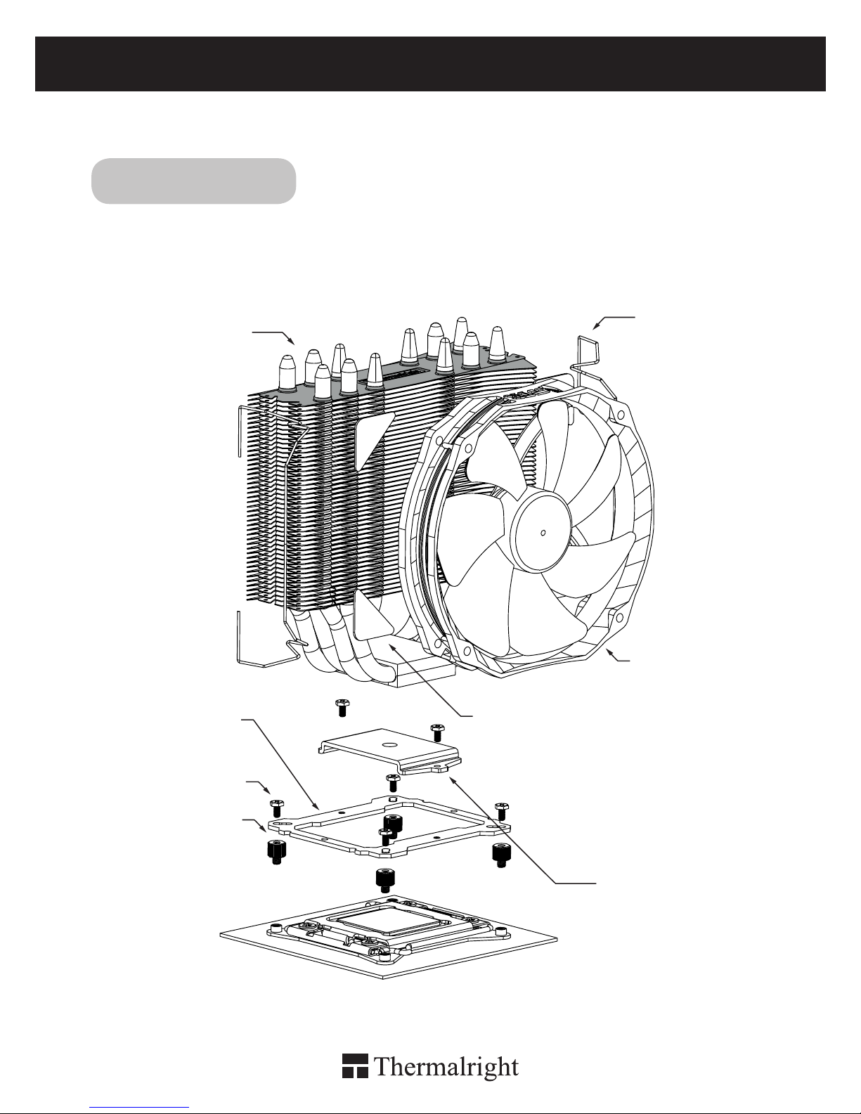
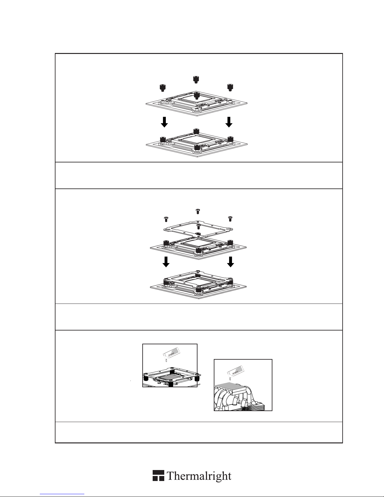
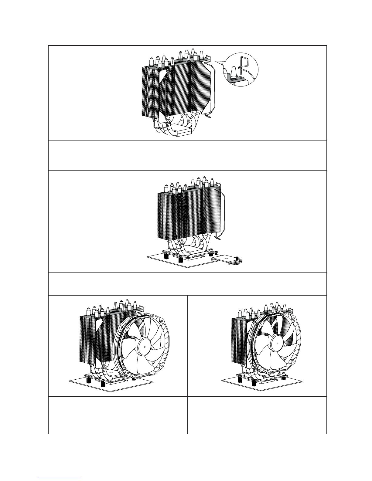
Thermalright
TRUE Spirit 140 Power


TRUE Spirit 140 Power
Assembly Package
× 4
× 7
× 1
× 1
× 1
4
4
8
× 4
× 5
× 1
× 8
× 1
× 4
× 4
× 4
Chill Factor 2g
× 1

TRUE Spirit 140 Power
1
Intel 775/1150/1155/1156/1366
Exploded View
Heatsink Body 14cm Fan Clip
TY147 FAN
M3 L10 Screw
Anti Vibration Pad
Mounting Plate
M3 L6 Screw
Anchoring Mount
Screw Nut
Intel Washer
(small)
Important! Before proceeding with installation, please check for the most
up-to-date instructions at www.themalright.com

The Ultimate Cooling Solutions!
www.thermalright.com
2
1
1
2
2
3
3
4
4
5
5
6
6
7 8
9
9
10 11
10
13
16
14
15 16
11
13
12
15
14
7 8
12
Heatsink Body ×1
LGA2011 Type B
Screw Pillars x4
M3 L6 Screw ×7
Back Plate Cap ×1
Mylar ×1
Thermal Paste ×1
Intel Washer (small) ×4
Mounting Plate ×1
Metal Back Plate ×1
M3 L10 Screw ×5
AMD Washer (big) ×4
Anchoring Mount ×1
Screw Nut ×4
14cm Fan Clip ×4
Anti Vibration Pad ×8
TY147 Fan ×1
Chill Factor 2g
Component

3
Installation Instructions:
Step 1:
Step 2:
Step 4:
Step 3:
Step 3 : Place the motherboard on top of the Back
Plate. See the four Screw Cylinders go through
the four holes around the processor socket.Cap
the four Screw Cylinders with the four Screw Nuts
in a criss-cross pattern.Make sure the side with a
washer is facing the Back Plate.
Step 5:
Step 4 : Anchoring Mount Installation
Place the Anchoring Mount on the Screw Nuts.
Use the four M3L6 Screws to x the Anchoring
Mount on to the Screw Pillars.
Step 5 : Applying Thermal Paste
Apply the Thermal Paste to the base of the
Heatsink and the surface of the CPU evenly.
Chill Factor
2g
Chill Factor
2g
Chill Factor
2g
Chill Factor
2g
1366
775 1156
1155
Step 1 : Backplate Installation
Choose the platform (775/1150/1155/1156/1366) you are in use. Make four M3L10 Screw Pillars go
through the Metal Back Plate and the Mylar lm from bottom towards top.And then place the Metal Back
Plate on the table. Put the four Washers (for Intel) around the Screw Pillars.
1
1
2
2
4
4
3
3
Step 2 : 775 backplate cap
Note: When installing on a 775 platform, please
rst insert the Back Plate Cap into the opening on
the Back plate, make sure you have the Cap facing
downwards. (Only for 775).

Step 6:
Step 7:
Step 8: Step 9:
Step 8 : Fan Installation
Place the included TY-147 14cm fan onto the
Heatsink body. And then secure it with the 14 cm
Fan Clips, by pulling the Fan Clips to place the
four ends at the four holes on the TY-147 fan.
Step 7 : Mounting Plate Installation
Place the Heatsink Body on top of the CPU. Make Mounting Plate go through the Heatsink Body. And
then use the two M3L6 screws to secure the Mounting Plate.
Step 9 : Installation Completed
Plug in the fan connector to the CPU PWM Fan
socket on the motherboard. Installation complete.
Step 6 : Part Installation
Take out TS140 cooler from the paper box. Remove the TY-147 fan from the cooler by pulling the Fan
Clips upwards in order to give room for ease of installation. And leave the fan clips on the Heatsink
Body. Do not remove them. Apply Anti-Vibration Padding to 4 corners on the Heatsink Body.

TRUE Spirit 140 Power
5
Exploded view
Heatsink Body 14cm Fan Clip
TY147 FAN
Anti Vibration Pad
Mounting Plate
Important! Before proceeding with installation, please check for the most
up-to-date instructions at www.themalright.com
M3 L6 Screw
Anchoring Mount
LGA2011 Type B
Screw Pillars
Intel 2011

The Ultimate Cooling Solutions!
www.thermalright.com
6
1
1
2
2
3
3
4
4
5
5
6
6
7 8
9
9
10 11
10
13
16
14
15 16
11
13
12
15
14
7 8
12
Heatsink Body ×1
LGA2011 Type B
Screw Pillars x4
M3 L6 Screw ×7
Back Plate Cap ×1
Mylar ×1
Thermal Paste ×1
Intel Washer (small) ×4
Mounting Plate ×1
Metal Back Plate ×1
M3 L10 Screw ×5
AMD Washer (big) ×4
Anchoring Mount ×1
Screw Nut ×4
14cm Fan Clip ×4
Anti Vibration Pad ×8
TY147 Fan ×1
Chill Factor 2g
Component

7
Chill Factor
2g
Chill Factor
2g
Installation Instructions:
Step 1:
Step 2:
Step 3:
Step 1 : Screw Pillar Installation
Screw on the four LGA2011 Type B Screw Pillars into the Heatsink studs on the ILM Assembly Frame
around the processor socket.
Step 2 : Anchoring Mount Installation
Place the Anchoring Mount onto the four LGA2011 Type B Screw Pillars, secure it by tightening it with 4
M3L6 Screws.
Step 3 : Applying Thermal Paste
Apply the Thermal Paste to the base of the Heatsink and the surface of the CPU evenly.
1
1
2
2
4
4
3
3
Chill Factor
2g
Chill Factor
2g

TRUE Spirit 140 Power
The Ultimate Cooling Solutions!
www.thermalright.com
8
Step 6:
Step 4:
Step 6 : Fan Installation
Place the included TY-147 Fan onto the Heatsink body. And then secure it with the 140mm Fan Clips,
by pulling the Fan Clips to place the four ends at the four holes on the TY-147 fan.
Step 7 : Installation Completed
Plug in the fan connector to the CPU PWM Fan socket on the motherboard. Installation complete.
Step 7:
Step 5:
Step 5 : Mounting Plate Installation
Place the Heatsink Body on top of the CPU. Make
Mounting Plate go through the Heatsink Body.
And then use the two M3L6 screws to secure the
Mounting Plate.
Step 4 : Fan Clip Installation
Pass each end of the Fan Clips through the
mounting holes on the cooler body. Then stick
one Anti Vibration Strip on each side of the cooler.

TRUE Spirit 140 Power
9
Heatsink Body 14cm Fan Clip
TY147 FAN
M3 L10 Screw
Anti Vibration Pad
Mounting Plate
M3 L6 Screw
Anchoring Mount
Screw Nut
AMD Washer
(big)
Exploded View
Important! Before proceeding with installation, please check for the most
up-to-date instructions at www.themalright.com
AM2/AM2+/AM3/AM3+/FM1/FM2

The Ultimate Cooling Solutions!
www.thermalright.com
10
Component
1
1
2
2
3
3
4
4
5
5
6
6
7 8
9
9
10 11
10
13
16
14
15 16
11
13
12
15
14
7 8
12
Heatsink Body ×1
LGA2011 Type B
Screw Pillars x4
M3 L6 Screw ×7
Back Plate Cap ×1
Mylar ×1
Thermal Paste ×1
Intel Washer (small) ×4
Mounting Plate ×1
Metal Back Plate ×1
M3 L10 Screw ×5
AMD Washer (big) ×4
Anchoring Mount ×1
Screw Nut ×4
14cm Fan Clip ×4
Anti Vibration Pad ×8
TY147 Fan ×1
Chill Factor 2g

11
Installation Instructions:
Step 1:
Step 2:
Step 4:
Step 3:
Step 1 : Backplate Installation
Choose the platform (AMD) you are in use. Make four M3L10 Screw Pillars go through the Metal Back
Plate and the Mylar lm from bottom towards top. And then place the Metal Back Plate on the table. Put
the four Washers (for AMD) around the Screw Pillars.
Step 5:
Step 5 : Anchoring Mount Installation
Place the Anchoring Mount on the Screw Nuts.
Use the four M3L6 Screws to x the Anchoring
Mount on to the Screw Nuts.
Step 6 : Applying Thermal Paste
Apply the Thermal Paste to the base of the
Heatsink and the surface of the CPU evenly.
Chill Factor
2g
Chill Factor
2g
AMD
Step 2 : Backplate cap
Note: When installing on a 939 platform, please
first insert the Back Plate Cap into the opening
on the Back plate, make sure you have the Cap
facing downwards. (Only for 939).
Step 4 : Place the motherboard on top of the Back
Plate. See the four Screw Pillars go through the
four holes around the processor socket.Cap the
four Screw Pillars with the four Screw in a criss-
cross pattern. Nuts.Make sure the side with a
washer is facing the Back Plate.
1
1
2
2
4
4
3
3
Chill Factor
2g
Chill Factor
2g

The Ultimate Cooling Solutions!
www.thermalright.com
12
Step 7:
Step 6:
Step 8: Step 9:
Step 8 : Fan Installation
Place the included TY-147 14cm fan onto the Heat
Sink body. And then secure it with the 14 cm Fan
Clips, by pulling the Fan Clips to place the four
ends at the four holes on the TY-147 fan.
Step 7 : Mounting Plate
Installation Place the Heat Sink Body on top of the CPU. Make Mounting Plate go through the Heatsink
Body. And then use the two M3L6 screws to secure the Mounting Plate.
Step 9 : Installation Completed
Plug in the fan connector to the CPU PWM Fan
socket on the motherboard. Installation complete.
Step 6 : Part Installation
Take out TS140 cooler from the paper box. Remove the TY-147 fan from the cooler by pulling the Fan
Clips upwards in order to give room for ease of installation. And leave the Fan Clips on the Heatsink
Body. Do not remove them. Apply Anti-Vibration Padding to 4 corners on the Heatsink Body.

TRUE Spirit 140 Power
25
Technical Spec
Heatsink Specifications:
Dimension: Length 155mm x Width 53.4mm x Height 171.2mm
Weight: 880g (Heatsink only)
Heatpipe: 8mm heatpipe*6 units
Copper Base: C1100 Pure copper nickel plated
Fan Specification:
Dimension: L152mm x H140mm x W26.5m
Weight: 160g
Fan speed: 900~1300 RPM (4-Pin PWM)
Fan noise: 17~21 dBA MAX (4-Pin PWM)
Airflow: 28.3~73.6 CFM MAX
Connector: 4 Pin (PWM Fan connector)

TRUE Spirit 140 Power
27
155
53.4
171.2
16.86 40.63 40
44.34
53


The Ultimate Cooling Solutions!
www.thermalright.com
TEL: +886-2-8663-6630
FAX: +886-2-8663-6645
EMAIL: [email protected]
Table of contents
Other Thermalright Fan manuals
Popular Fan manuals by other brands

Helios
Helios ultra Silence ELS EC Series Installation and operating instructions

Kampmann
Kampmann Venkon XL Assembly, installation and operating instructions

Star Fans
Star Fans STAR X user manual

Onix
Onix FE10-C user manual

Parrot Uncle
Parrot Uncle F6272110V Installation & operating instructions

Goldair
Goldair Platinum GPTF390 operating instructions